10-Gigabit Ethernet Switch Performance Testing - Ixia
10-Gigabit Ethernet Switch Performance Testing - Ixia
10-Gigabit Ethernet Switch Performance Testing - Ixia

Create successful ePaper yourself
Turn your PDF publications into a flip-book with our unique Google optimized e-Paper software.
Enabling a Converged World <br />
<strong>10</strong>-<strong>Gigabit</strong> <strong>Ethernet</strong> <strong>Switch</strong><br />
<strong>Performance</strong> <strong>Testing</strong>
White Paper<br />
<strong>10</strong>-<strong>Gigabit</strong> <strong>Ethernet</strong> <strong>Switch</strong><br />
<strong>Performance</strong> <strong>Testing</strong><br />
sample test plans included
Copyright © 1998-2004 <strong>Ixia</strong>. All rights reserved.<br />
The information in this document is furnished for<br />
informational use only, is subject to change<br />
without notice, and should not be construed as a<br />
commitment by <strong>Ixia</strong>. <strong>Ixia</strong> assumes no<br />
responsibility or liability for any errors or<br />
inaccuracies that may appear in this document.<br />
<strong>Ixia</strong> and the <strong>Ixia</strong> logo are trademarks of <strong>Ixia</strong>. All<br />
other companies, product names, and logos are<br />
trademarks or registered trademarks of their<br />
respective holders.<br />
<strong>Ixia</strong><br />
26601 W. Agoura Road<br />
Calabasas, CA 91302<br />
Phone: (818) 871-1800<br />
Fax: (818) 871-1805<br />
Email: info@ixiacom.com<br />
Internet: www.ixiacom.com<br />
2 Copyright © 2004, <strong>Ixia</strong> <strong>10</strong>-<strong>Gigabit</strong> <strong>Ethernet</strong> <strong>Switch</strong> <strong>Performance</strong> <strong>Testing</strong>
Contents<br />
Abstract .....................................................................................................................................5<br />
Introduction ..............................................................................................................................5<br />
<strong>10</strong>-<strong>Gigabit</strong> <strong>Ethernet</strong> LAN ...................................................................................................6<br />
<strong>10</strong>-<strong>Gigabit</strong> <strong>Ethernet</strong> Metro ................................................................................................6<br />
<strong>10</strong>-<strong>Gigabit</strong> <strong>Ethernet</strong> WAN ..................................................................................................6<br />
What Is Inside a Multi-<strong>10</strong>GE Port <strong>Switch</strong>? ..............................................................................7<br />
Packet buffer .....................................................................................................................7<br />
Packet processing function ..............................................................................................7<br />
Classification tables ..........................................................................................................7<br />
Context memory ................................................................................................................7<br />
Traffic management function ...........................................................................................7<br />
<strong>Switch</strong> fabric ......................................................................................................................7<br />
What Happens to a Packet When It Enters a <strong>10</strong>GE Port? .....................................................8<br />
Storing the packet .............................................................................................................8<br />
Processing the packet .......................................................................................................8<br />
Metering and statistics recording .................................................................................. <strong>10</strong><br />
Packet modification ....................................................................................................... <strong>10</strong><br />
Traffic management ....................................................................................................... <strong>10</strong><br />
<strong>Switch</strong> fabric ................................................................................................................... <strong>10</strong><br />
What Are the Challenges in Processing Packets at <strong>10</strong>G Rates? ....................................... 11<br />
Stress Point 1: Ingress packet buffer ............................................................................ 11<br />
Stress Point 2: Packet classification ............................................................................. 11<br />
Stress Point 3: Traffic management ............................................................................. 13<br />
Stress Point 4: Crossbar switch and backplane interconnect .................................... 14<br />
Stress Point 5: Multicast replication and queues ........................................................ 14<br />
Stress Point 6: Control plane ......................................................................................... 15<br />
Developing the Right Test Methodology .............................................................................. 16<br />
Test methodology example ............................................................................................ 16<br />
Module-level testing ....................................................................................................... 16<br />
System-level testing ....................................................................................................... 16<br />
Test methodologies ........................................................................................................ 16<br />
Anticipating the behavior of the <strong>10</strong>GE switch .............................................................. 18<br />
<strong>Ixia</strong>’s Test Solution ............................................................................................................... 20<br />
IxExplorer ........................................................................................................................ 20<br />
IxScriptMate .................................................................................................................... 20<br />
Appendix: <strong>10</strong>GE <strong>Testing</strong> Examples ...................................................................................... 22<br />
1. Throughput <strong>Testing</strong>: RFC 2544 Throughput Test .................................................... 22<br />
2. <strong>Testing</strong> for Latency: RFC 2544 Latency Tests ......................................................... 24<br />
3. <strong>Testing</strong> how <strong>10</strong>GE ports handle prioritized streams based on QoS parameters .. 25<br />
4. <strong>10</strong>GE OSPF Convergence Test .................................................................................. 27<br />
Glossary ................................................................................................................................. 29<br />
Acknowledgements ...............................................................................................................30<br />
<strong>10</strong>-<strong>Gigabit</strong> <strong>Ethernet</strong> <strong>Switch</strong> <strong>Performance</strong> <strong>Testing</strong> Copyright © 2004, <strong>Ixia</strong> 3
4 Copyright © 2004, <strong>Ixia</strong> <strong>10</strong>-<strong>Gigabit</strong> <strong>Ethernet</strong> <strong>Switch</strong> <strong>Performance</strong> <strong>Testing</strong>
<strong>10</strong>-<strong>Gigabit</strong> <strong>Ethernet</strong> <strong>Switch</strong> <strong>Performance</strong> <strong>Testing</strong><br />
Abstract The first generation of <strong>10</strong>-<strong>Gigabit</strong> <strong>Ethernet</strong><br />
(<strong>10</strong>GE) switches, introduced in early 2002<br />
after IEEE 802.3ae standardization,<br />
proved to be subpar. Some switches barely<br />
reached 50 percent of line rate<br />
throughput, even for large packet sizes,<br />
and exhibited poor latency, limited feature<br />
sets, and high per-port costs.<br />
The second generation of <strong>10</strong>GE products<br />
has arrived, with substantial packet<br />
processing capabilities that enable<br />
additional services. Key functions in this<br />
Introduction <strong>Ethernet</strong> networking technology is now<br />
virtually ubiquitous; it has evolved from<br />
<strong>10</strong>Base-T (IEEE 802.3) in 1983, Fast<br />
<strong>Ethernet</strong> (IEEE 802.3u) in 1995, 1-<strong>Gigabit</strong><br />
<strong>Ethernet</strong> (802.3z) in 1998 to <strong>10</strong>-<strong>Gigabit</strong><br />
<strong>Ethernet</strong> (802.3ae) in 2002. The <strong>10</strong>-<br />
<strong>Gigabit</strong> <strong>Ethernet</strong> standard provides a<br />
significant increase in bandwidth while<br />
maintaining compatibility with the installed<br />
base of 802.3-standard interfaces, to<br />
protect existing investments in <strong>Ethernet</strong><br />
technology. The IEEE 802.3ae <strong>10</strong>-<strong>Gigabit</strong><br />
<strong>Ethernet</strong> standard defines both LAN and<br />
WAN physical layers, the latter of which is<br />
compatible with existing SONET<br />
infrastructure.<br />
<strong>Ethernet</strong> not only dominates the LAN<br />
market, but is also taking hold in the Metro<br />
Area Network (MAN) market. It has<br />
extended into the WAN arena as both its<br />
distance and capacity has increased.<br />
<strong>Ethernet</strong> at 1-<strong>Gigabit</strong> and <strong>10</strong>-<strong>Gigabit</strong><br />
speeds has attracted increasing attention<br />
from carriers operating in the MAN and<br />
WAN market segments.<br />
technology include performing the<br />
necessary packet classification, header<br />
modification, policing of flows, and<br />
queuing/scheduling — all at wire-speed<br />
rates.<br />
This white paper reviews the common<br />
building blocks of a multiple line card<br />
<strong>10</strong>GE switch, identifies various stress<br />
points within the switch, and offers various<br />
test methodologies to test these stress<br />
points.<br />
After nearly two years of slow growth<br />
during 2001 and 2002, worldwide Layer 2<br />
and Layer 3 <strong>Ethernet</strong> switch revenue<br />
began to accelerate in mid-2003, and is<br />
expected to grow from $11.8 billion in<br />
2004 to $15 billion in 2006, according to<br />
Infonetics Research's quarterly market<br />
share and forecast service, L2–L3<br />
<strong>Ethernet</strong> <strong>Switch</strong>es. Worldwide port<br />
shipments are predicted to grow 75<br />
percent — from 161 million in 2003 to 279<br />
million in 2006.<br />
The strongest growth in the <strong>Ethernet</strong><br />
switch market has come from <strong>10</strong>GE<br />
chassis ports and revenue, driven by <strong>10</strong>GE<br />
deployment in service provider metro<br />
networks, and by the proliferation of 1GE<br />
to desktops/laptops as a standard<br />
interface.<br />
<strong>10</strong>-<strong>Gigabit</strong> <strong>Ethernet</strong> has been developed to<br />
support a wide range of applications —<br />
from the enterprise network, through the<br />
edge and metro network, and into the wide<br />
area network.<br />
<strong>10</strong>-<strong>Gigabit</strong> <strong>Ethernet</strong> <strong>Switch</strong> <strong>Performance</strong> <strong>Testing</strong> Copyright © 2004, <strong>Ixia</strong> 5
<strong>10</strong>-<strong>Gigabit</strong> <strong>Ethernet</strong> LAN<br />
The biggest market for <strong>10</strong>-<strong>Gigabit</strong> <strong>Ethernet</strong><br />
is likely to be in the corporate backbone.<br />
The cost of 1-<strong>Gigabit</strong> and <strong>10</strong>-<strong>Gigabit</strong><br />
<strong>Ethernet</strong> has dropped significantly, which<br />
will trigger the demand for <strong>10</strong>GE services<br />
and products.<br />
In the enterprise network, <strong>10</strong>-<strong>Gigabit</strong><br />
<strong>Ethernet</strong> is used for:<br />
• <strong>Switch</strong>-to-switch links for very highspeed<br />
connections within the same<br />
wiring closet or data center or between<br />
different buildings.<br />
• Aggregation of multiple-fiber<br />
<strong>10</strong>00BASE-X or copper <strong>10</strong>00BASE-T<br />
segments into <strong>10</strong>GE uplinks. Nearly all<br />
new desktops and laptops are now<br />
shipped with <strong>10</strong>/<strong>10</strong>0/<strong>10</strong>00BASE-T<br />
ports.<br />
•System Area Networking (SAN)<br />
applications providing server<br />
interconnects for clusters of servers.<br />
<strong>10</strong>-<strong>Gigabit</strong> <strong>Ethernet</strong> plays a key role in<br />
interconnecting the new generation of<br />
high-performance servers with multigigahertz<br />
2/4/8-way processors<br />
required for moving large amount of<br />
data between server farms.<br />
<strong>10</strong>-<strong>Gigabit</strong> <strong>Ethernet</strong> Metro<br />
At the Metro Area Network (MAN) level,<br />
service providers face tremendous<br />
pressure to expand capacity for broadband<br />
local access, high-speed WANs, storage,<br />
and campus /enterprise grids. Standardsbased<br />
<strong>10</strong>-<strong>Gigabit</strong> <strong>Ethernet</strong> enables service<br />
providers to extend their <strong>10</strong>GE networks<br />
into the metro edge using their dark fiber,<br />
especially when <strong>10</strong>GE is combined with<br />
metro area optical fiber networks based on<br />
Wave Division Multiplexing (WDM).<br />
<strong>10</strong>GE MANs can be deployed in either a<br />
star or ring topology. Unlike Resilient<br />
Packet Ring (RPR) networks, <strong>10</strong>GE<br />
networks use the standard <strong>Ethernet</strong> MAC<br />
protocol. The latest <strong>10</strong>GE metro switches<br />
can provide network reliability similar to<br />
that of networks based on SONET/SDH<br />
rings.<br />
<strong>10</strong>-<strong>Gigabit</strong> <strong>Ethernet</strong> WAN<br />
<strong>10</strong>GE WAN applications are similar to MAN<br />
applications, but leverage existing SONET<br />
networks rather than new infrastructure.<br />
SONET is the dominant transport protocol<br />
in the WAN backbone today, and most<br />
MAN public services are offered over<br />
SONET networks.<br />
The <strong>10</strong>-<strong>Gigabit</strong> <strong>Ethernet</strong> interface (WAN<br />
PHY) is compatible with SONET-based Time<br />
Division Multiplexing (TDM) and with the<br />
payload rate of OC-192c/SDH VC-4-64c.<br />
The <strong>10</strong>-<strong>Gigabit</strong> WAN interface facilitates<br />
the transport of native <strong>Ethernet</strong> packets<br />
across the WAN transport network, with no<br />
need for protocol conversion. This not only<br />
improves the performance of the network,<br />
but makes it simpler and less costly to<br />
manage.<br />
<strong>Ethernet</strong>’s flexibility and universal<br />
availability will fuel the demand for <strong>10</strong>-<br />
<strong>Gigabit</strong> <strong>Ethernet</strong> deployment in multiple<br />
network segments, from corporate<br />
networks, to data centers, and throughout<br />
service provider networks. This ongoing<br />
demand will require system vendors to<br />
deliver high-performing <strong>10</strong>-<strong>Gigabit</strong> systems<br />
that meet service providers’ stringent<br />
requirements — requirements that ensure<br />
high availability to corporate networks and<br />
performance that meets service level<br />
agreements (SLAs).<br />
6 Copyright © 2004, <strong>Ixia</strong> <strong>10</strong>-<strong>Gigabit</strong> <strong>Ethernet</strong> <strong>Switch</strong> <strong>Performance</strong> <strong>Testing</strong>
What Is Inside a<br />
Multi-<strong>10</strong>GE Port<br />
<strong>Switch</strong>?<br />
<strong>Testing</strong> the new generation of <strong>10</strong>GE<br />
switches requires a clear understanding of<br />
the various building blocks that make up a<br />
switch, and their interaction, to determine<br />
the various stress points within a switch<br />
and identify the weakest link in the chain.<br />
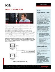
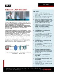
Figure 1 shows the major components of a<br />
<strong>10</strong>GE switch, including the line card, the<br />
switch fabric card, and the controller card.<br />
The following subsections provide an<br />
overview of the <strong>10</strong>GE switch/router<br />
components crucial to performance<br />
testing.<br />
Packet buffer<br />
The packet buffer is a temporary repository<br />
for arriving packets while they wait to be<br />
processed.<br />
Packet processing function<br />
The packet processor is an optimized ASIC<br />
or programmable device (Network<br />
Processing Unit, or NPU) for processing<br />
and forwarding packets in the data plane<br />
or fast path. It performs specific key tasks<br />
such as parsing the header, pattern<br />
matching or classification, table look-ups,<br />
packet modification, and packet<br />
forwarding, ideally at wire speed.<br />
Classification tables<br />
The classification table is a special<br />
memory used by the packet processor. It<br />
may contain the following databases:<br />
•The routing table determines where to<br />
route incoming packets.<br />
• Access Control Lists (ACLs) contain<br />
information to grant or deny<br />
permission to specific users or groups<br />
•The flow classification table contains<br />
information about a particular user or<br />
group of users, protocols, and<br />
applications. Flow identification<br />
information is used to determine QoS<br />
treatment, packet policing, and perflow<br />
queuing and billing.<br />
•The label table contains information<br />
about VLANs, stacked VLANs, MPLS<br />
labels, etc.<br />
Context memory<br />
Context memory contains instructions<br />
about whether to deny or forward packets,<br />
where to forward them, all the internal<br />
system headers needed to get a packet<br />
from an ingress to an egress port, and the<br />
external packet header (new MAC, IP,<br />
MPLS stacks, etc.). It also holds<br />
information relevant to metering the<br />
packet and other miscellaneous<br />
information about how to process a<br />
packet.<br />
Traffic management function<br />
The traffic management function is used<br />
to regulate the flow of traffic. It forwards<br />
traffic according to a user-defined set of<br />
rules pertaining to priority levels, latency<br />
and bandwidth guarantees, and<br />
congestion levels. It also provides the<br />
buffering required to work with any<br />
queuing mechanisms it uses to manage<br />
traffic flow across the switch fabric. It may<br />
also include the high-speed SERDES<br />
(serializer/deserializer) function used to<br />
connect to the switch fabric.<br />
<strong>Switch</strong> fabric<br />
The switch fabric provides data plane<br />
interconnection among all line cards in the<br />
system. The switch fabric typically employs<br />
a crossbar to move packets between its<br />
ingress and egress ports. An NxN crossbar<br />
switch fabric allows N line cards in a<br />
system to be interconnected in a chassis.<br />
This allows each slot to simultaneously<br />
send and receive traffic over the switch<br />
fabric.<br />
<strong>10</strong>-<strong>Gigabit</strong> <strong>Ethernet</strong> <strong>Switch</strong> <strong>Performance</strong> <strong>Testing</strong> Copyright © 2004, <strong>Ixia</strong> 7
What Happens to a<br />
Packet When It<br />
Enters a <strong>10</strong>GE Port?<br />
Figure 1. <strong>10</strong>GE switch building blocks.<br />
This section provides a high-level<br />
walkthrough of the “life of a packet” as it<br />
goes from a port on an ingress line card<br />
through the switch fabric card and exits on<br />
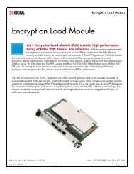
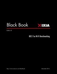
an egress line card. Figure 2 shows the<br />
logical operation of various line cards in a<br />
multi-<strong>10</strong>GE port switch, and identifies the<br />
stress points (numbered red circles).<br />
Storing the packet<br />
When a packet arrives on a <strong>10</strong>GE port, it is<br />
stored in ingress buffer memory while<br />
waiting to be processed by the packet<br />
processor. When the packet processor is<br />
ready, the packet header is copied into the<br />
packet processor memory for processing.<br />
Processing the packet<br />
The packet processor (ASIC or NPU)<br />
examines the packet to determine whether<br />
a packet should be filtered or forwarded. It<br />
makes this determination by parsing the<br />
packet header and then performing packet<br />
and flow classification.<br />
The classification process maps<br />
information extracted from the packet<br />
header to information stored in local tables<br />
maintained by the control plane processor.<br />
The information in the classification tables<br />
typically includes forwarding tables,<br />
routing tables, and profiles or rules for a<br />
given packet or flow, such as policies for<br />
ACLs, Quality of Service (QoS), and Class of<br />
Service (CoS).<br />
The classification typically points to many<br />
fragments of information about a packet.<br />
This information is usually saved in context<br />
memory and may contain instructions<br />
about whether to deny or forward the<br />
packet, where to forward it, all additional<br />
header information to get a packet from<br />
ingress to egress port, the new header<br />
used when it leaves the egress port (new<br />
MAC, IP, MPLS stacks, etc.), information<br />
relevant to policing the packet (see<br />
"Metering and statistics recording" below),<br />
and other information about how to<br />
process the packet.<br />
8 Copyright © 2004, <strong>Ixia</strong> <strong>10</strong>-<strong>Gigabit</strong> <strong>Ethernet</strong> <strong>Switch</strong> <strong>Performance</strong> <strong>Testing</strong>
Figure 2. Logical operation of line cards in a multi-<strong>10</strong>GE port switch with stress points.<br />
<strong>10</strong>-<strong>Gigabit</strong> <strong>Ethernet</strong> <strong>Switch</strong> <strong>Performance</strong> <strong>Testing</strong> Copyright © 2004, <strong>Ixia</strong> 9
Metering and statistics recording<br />
Packet metering checks the conformance<br />
of a flow to a subscribed traffic policy or<br />
contract. The metered information is then<br />
used to decide whether to discard or<br />
forward the packet. Bandwidth allocations<br />
may be established in contracts that<br />
specify the per-flow, steady state, and<br />
short term peak (burst) rates. Typically, a<br />
Token Bucket Algorithm is used at the<br />
ingress port to check the compliance of<br />
each flow to its contract. (A detailed<br />
discussion of the Token Bucket Algorithm<br />
is outside the scope of this document). The<br />
metered packets that violate the assigned<br />
contract can be marked for a range of<br />
treatments: unconditional drop, drop if no<br />
internal resources available, or pass on<br />
the packet dropping decision to the<br />
downstream device. The marking of<br />
packets can also be used by the egress<br />
line card to decide whether to delay<br />
packets within a packet stream in order to<br />
conform to some defined traffic profile,<br />
referred to as traffic shaping. Traffic<br />
shaping is used to smooth out packet flows<br />
and regulate the rate and volume of traffic<br />
admitted to the network.<br />
Packet modification<br />
Based on the outcome of the classification<br />
process, the next step is to modify the<br />
packet header and determine the packet’s<br />
egress port. Context memory contains<br />
instructions about whether to deny or<br />
forward packets, where to forward them,<br />
and all the internal system headers<br />
needed to get a packet from an ingress to<br />
an egress port. On the egress line card, a<br />
new external packet header (new MAC, IP,<br />
MPLS stacks, etc.) will be inserted by the<br />
egress packet processing function.<br />
Traffic management<br />
The packet processor typically appends an<br />
internal forwarding header to each packet<br />
that it forwards to the traffic management<br />
device. This header contains information<br />
that tells the ingress/egress traffic<br />
managers where to forward the packet<br />
(which port and line card) and the<br />
characteristics of the flow. The traffic<br />
manager then passes through or discards<br />
flagged packets, depending on its policies<br />
for the ingress direction.<br />
Depending on the architecture, forwarded<br />
packets are organized into FIFO (First-In,<br />
First-Out) queues, input queues, or Virtual<br />
Output Queues (VOQs). Queued traffic is<br />
then scheduled for transmission to the<br />
switch fabric based on a scheduling<br />
algorithm — for example, Weighted Round<br />
Robin (WRR), Weighted Fair Queuing<br />
(WFQ), etc.<br />
Depending on whether or not the switch<br />
fabric supports fixed or variable length<br />
packets, packet segmentation into fixed<br />
cells may occur before packets are<br />
transmitted onto the backplane. The<br />
ingress traffic manager typically interacts<br />
with the switch fabric and/or egress traffic<br />
manager to meet switch fabric scheduling<br />
requirements and avoid congestion.<br />
On the egress side, the traffic manager<br />
first performs a reassembly operation if<br />
segmentation was performed on the<br />
ingress side. Received packets are then<br />
placed into an output queue based on<br />
information from the header that was<br />
appended at ingress. If per-flow queuing is<br />
supported, the egress traffic manager<br />
maintains an additional output queue for<br />
each flow. Each output queue provides<br />
traffic shaping to maintain conformance to<br />
QoS policy.<br />
<strong>Switch</strong> fabric<br />
The switch fabric functions as a highperformance<br />
data plane interconnect<br />
between its ingress and egress ports. Most<br />
new crossbar switch architectures have<br />
embedded high speed SERDES (serializer/<br />
deserializer) interconnecting line cards<br />
through centralized switch devices. A<br />
packet entering a switch is transferred to<br />
the switching engine. The switching engine<br />
<strong>10</strong> Copyright © 2004, <strong>Ixia</strong> <strong>10</strong>-<strong>Gigabit</strong> <strong>Ethernet</strong> <strong>Switch</strong> <strong>Performance</strong> <strong>Testing</strong>
What Are the<br />
Challenges in<br />
Processing Packets<br />
at <strong>10</strong>G Rates?<br />
then examines the packet header and<br />
decides where to forward the packet.<br />
When multiple ingress ports contend for<br />
an egress port, congestion becomes the<br />
primary issue at the egress switch port<br />
and, depending on the architecture, may<br />
cause Head-of-Line blocking (HOL). HOL<br />
blocking occurs with input queuing, when a<br />
cell (a segmented packet to be transmitted<br />
across the backplane) has to be held up,<br />
thereby blocking the progress of any cells<br />
This section examines the most common<br />
stress points within a switch, and<br />
discusses conditions that might push them<br />
toward a strained state. Refer to Figure 2.<br />
Stress Point 1: Ingress packet buffer<br />
The ingress packet buffer is a temporary<br />
repository for arriving packets waiting to be<br />
processed by the packet processor.<br />
Depending on the architecture and<br />
efficiency of the packet processor, data in<br />
the packet buffer could build up, resulting<br />
in intermittent (poor) latency, jitter, packet<br />
loss, or even service outage.<br />
In most architectures, when packet buffers<br />
begin to fill beyond a preset threshold, the<br />
packet processor initiates flow control to<br />
the upstream MAC device, requesting it to<br />
stop passing packets. The MAC device<br />
then transmits a special packet requesting<br />
remote ports to delay sending packets for<br />
a period of time. This special packet is<br />
called a pause frame. This helps prevent<br />
buffer overflow, but it does not solve the<br />
packet loss problem completely. If the<br />
packet flow continues and the flow control<br />
signal is not removed by the packet<br />
processor before the MAC device’s buffer<br />
fills up, the MAC device will start dropping<br />
packets.<br />
Generally, the buffer in any part of the<br />
system can build up for two reasons:<br />
• Local or downstream devices are<br />
exceeding their allocated processing<br />
budget; or<br />
behind it, even if they could otherwise be<br />
switched.<br />
Some switch architectures also provide<br />
multicast packet replication. To get around<br />
packet replication issues, most modern<br />
switch fabrics now allow for an incoming<br />
packet to be broadcast to any number of<br />
egress ports. Typically, on the ingress and<br />
egress line cards, separate queues and<br />
scheduling disciplines are maintained for<br />
unicast and multicast traffic.<br />
• There is contention for resources — for<br />
instance, multiple ingress ports on a<br />
switch/router contending for an egress<br />
port.<br />
Buffer buildup can create a chain reaction,<br />
leading to unpredictable behavior in a<br />
switch or router.<br />
Another challenge in packet buffering for<br />
<strong>10</strong>GE switches is dealing with back-to-back<br />
small packets. For example, at <strong>10</strong> Gbps<br />
speeds, arriving 64-byte packets must be<br />
deposited into buffer memory every 67<br />
nanoseconds (ns), and departing packets<br />
must be retrieved from buffer memory<br />
every 67ns. Thus, to process a stream of<br />
back-to-back 64-byte packets, the packet<br />
buffer memory subsystem must support a<br />
write and a read every 67ns.<br />
Stress Point 2: Packet classification<br />
Packet classification is one of the most<br />
susceptible stress points. Classification<br />
maps information from the packet header<br />
to information stored in local tables<br />
maintained by a control plane processor<br />
(see "Stress Point 6: Control plane"). The<br />
packet processor parses various fields in<br />
the packet header to construct search<br />
keys. These keys are then used to address<br />
various tables. In most high-end<br />
architectures, Ternary Content<br />
Addressable Memory (TCAM) devices or<br />
equivalent technologies are used to map<br />
these keys to addresses, and are capable<br />
of holding millions of entries and<br />
<strong>10</strong>-<strong>Gigabit</strong> <strong>Ethernet</strong> <strong>Switch</strong> <strong>Performance</strong> <strong>Testing</strong> Copyright © 2004, <strong>Ixia</strong> 11
performing key searches in a matter of few<br />
internal clock cycles. However, complex<br />
applications or routing protocols may<br />
require multiple key searches to drive a<br />
look-up result. Furthermore, separate<br />
classification sequences may be required<br />
to determine what to do with a packet. For<br />
example, the packet processor may<br />
perform an ACL look-up first to decide<br />
whether to forward or deny a packet, and<br />
then do a route look-up to decide where to<br />
forward it. It might also perform a flow<br />
control look-up to provide enhanced<br />
services.<br />
The required degree of packet parsing and<br />
processing is one of the main criteria that<br />
identifies the class of a switch/router. A<br />
simple Layer 2-3 switch only inspects the<br />
L2 header (i.e., MAC header, VLAN), and<br />
the L3 header (i.e., IPv4, IPv6), and, in<br />
some cases, performs limited flow<br />
classification.<br />
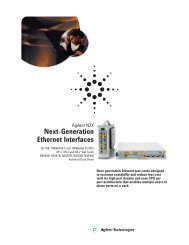
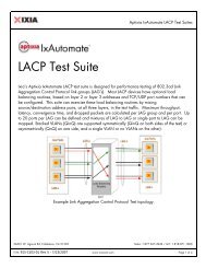
Complex packets might require the<br />
classification of multiple L2-L3 headers for<br />
a given packet. Packets of a given protocol<br />
may be encapsulated within one or more<br />
tunnels of varying protocols, as shown in<br />
Figure 3. For example, a system supporting<br />
IPv6 over GRE requires two Layer 3<br />
headers (IPv4 and IPv6) in addition to the<br />
Layer 2 MAC addresses. A more complex<br />
example is a Layer 2 VPN Martini Draft<br />
IPv6 over GRE packet<br />
Dest<br />
MAC<br />
Dest<br />
MAC<br />
Src<br />
MAC Type<br />
Src<br />
MAC<br />
IPv4<br />
header<br />
<strong>Ethernet</strong> over MPLS packet<br />
Type MPLS<br />
label<br />
GRE<br />
IPv6<br />
header<br />
EXP S TTL Dest<br />
MAC<br />
packet with frames arriving over <strong>Ethernet</strong><br />
in a wide range of dispositions, including<br />
IPv4 routing, MPLS switching or <strong>Ethernet</strong><br />
bridging.<br />
Flow classification. In addition to complex<br />
packet classification, flow classification<br />
might be required to provide enhanced<br />
services and policies. Flow classification<br />
provides a level of granularity that allows<br />
policies to be established based on the<br />
applications. Any number of combinations<br />
of Layer 3 and Layer 4 information could<br />
be employed to define the QoS or security<br />
policies that are then enforced.<br />
A flow is a collection of one or more packet<br />
streams. In some classes of switches/<br />
routers, in addition to packet classification,<br />
flow classifiers perform stateful analysis of<br />
packets within the packet streams. Flow<br />
classifiers track the protocol state of each<br />
flow as the connection develops. This<br />
makes it possible to track control<br />
connections on well-known ports that<br />
spawn data connections on ephemeral<br />
ports. This is important, since many<br />
protocols establish connections and<br />
negotiate services on well-known<br />
Transmission Control Protocol (TCP) ports<br />
and then establish another ephemeral<br />
port to transfer the data for the network<br />
session.<br />
TCP/UDP<br />
datagram<br />
Figure 3. Packets may be encapsulated in tunnels of varying protocols.<br />
12 Copyright © 2004, <strong>Ixia</strong> <strong>10</strong>-<strong>Gigabit</strong> <strong>Ethernet</strong> <strong>Switch</strong> <strong>Performance</strong> <strong>Testing</strong><br />
Src<br />
MAC<br />
Type<br />
IPv4<br />
header<br />
TCP/UDP<br />
datagram
Table 1. Maximum packet arrival rates over <strong>10</strong>-<strong>Gigabit</strong> <strong>Ethernet</strong>.<br />
Look-ups and performance. Classification<br />
table information is typically stored in a<br />
look-up table, usually held in a large TCAM<br />
or equivalent technology. When processing<br />
encapsulated packets or packets with<br />
multiple L2/L3 headers (i.e., IPv6 over<br />
IPv4, or MPLS stacks with <strong>Ethernet</strong> header,<br />
IP header, and TCP) the classification<br />
process might require multiple accesses to<br />
the look-up table for each packet.<br />
Table 1 shows the worst-case performance<br />
packet arrival rate for small packets.<br />
Depending on the packet arrival rate and<br />
number of required look-ups per packet,<br />
the packet processor or the classification<br />
device could become a resource<br />
bottleneck. For example, a back-to-back<br />
<strong>Ethernet</strong> packet with an IPv6 datagram<br />
requiring ACL and flow look-up might<br />
require 7–8 look-ups per packet. With 12<br />
million packets arriving per second, this<br />
will require handling ~96 million look-ups/<br />
sec.<br />
Stress Point 3: Traffic management<br />
The traffic management function provides<br />
advanced queuing, congestion<br />
management, and hierarchical scheduling<br />
of network traffic for large numbers of<br />
flows. It forwards traffic according to a<br />
user-defined set of rules pertaining to<br />
priority levels, latency and bandwidth<br />
guarantees, and varying congestion levels.<br />
It also provides the packet buffering<br />
required to work with any queuing<br />
mechanisms used to manage traffic flow<br />
Wire rate LAN throughput for minimum-size packet<br />
<strong>Ethernet</strong> IPv4 14.88 million packets/sec<br />
<strong>Ethernet</strong> IPv6 12.02 million packets/sec<br />
<strong>Ethernet</strong> Over MPLS IPv4 12.25 million packets/sec<br />
<strong>Ethernet</strong> Over MPLS IPv6 <strong>10</strong>.25 million packets/sec<br />
across the switch fabric. It may also<br />
include the SERDES function.<br />
Communication from line card to switch<br />
fabric requires additional flow control<br />
information, creating overhead and<br />
increased bandwidth. This additional<br />
bandwidth is called speedup. See "Speedup."<br />
on page 14.<br />
The architecture of a switch/router can<br />
affect how the network behaves in times of<br />
heavy demand. An important concern is<br />
how packets are queued as they enter the<br />
switching fabric, that is, how traffic<br />
prioritization is handled and how different<br />
traffic flows are merged through the fabric.<br />
Some products forward all high-priority<br />
packets before any lower-priority packets;<br />
this is called strict priority queuing. Other<br />
products use mechanisms such as<br />
Weighted Fair Queuing (WFQ) to<br />
statistically multiplex packets into the<br />
fabric. On the ingress line card, WFQ allows<br />
packets from lower priority queues to be<br />
interleaved with higher priority traffic into<br />
the switch fabric. This prevents the higher<br />
priority traffic from completely blocking the<br />
lower priority traffic, since the queues are<br />
guaranteed access to the switch fabric for<br />
a predefined proportion of the time.<br />
Packet discarding is also part of traffic<br />
management. During times of congestion,<br />
the traffic manager may need to make<br />
discard decisions based on the availability<br />
of queue space, priority, or destination<br />
port, using a packet discard algorithm like<br />
<strong>10</strong>-<strong>Gigabit</strong> <strong>Ethernet</strong> <strong>Switch</strong> <strong>Performance</strong> <strong>Testing</strong> Copyright © 2004, <strong>Ixia</strong> 13
Random Early Detection (RED) or Weighted<br />
RED (WRED) for IP traffic.<br />
Some routers and switches are<br />
fundamentally limited by the small number<br />
of queues they have for QoS. Small<br />
numbers of queues are common for classbased<br />
queuing, which limits prioritization<br />
and fairness. Class-based queuing typically<br />
prioritizes traffic based on the Layer 2<br />
header (virtual LAN and source or<br />
destination MAC address, for example),<br />
rather than on higher level information<br />
such as application or protocol type.<br />
Systems with large numbers of queues<br />
facilitate more granular prioritization and<br />
greater fairness. Queues established on a<br />
per-flow basis provide the possibility for<br />
each user session to get its own queue.<br />
However, a large number of CoS and QoS<br />
policies requires large amounts of memory<br />
and hierarchical schedulers capable of<br />
handling hundreds of thousands of flows.<br />
Stress Point 4: Crossbar switch and backplane<br />
interconnect<br />
Although most switch architectures for<br />
modern systems are non-blocking, three<br />
types of blocking can limit performance<br />
when multiple ingress ports are<br />
contending for an egress port: Head-of-<br />
Line (HOL) blocking, input blocking, and<br />
output blocking. HOL blocking can waste<br />
nearly half a crossbar switch's bandwidth if<br />
the cells waiting at each input are stored in<br />
a single First-In, First-Out (FIFO) queue.<br />
Modern switch architectures employ<br />
Virtual Output Queuing (VOQ). VOQ, in<br />
conjunction with a scheduling algorithm,<br />
eliminates most blocking issues. These<br />
scheduling algorithms require the traffic<br />
manager device and the switch fabric to<br />
exchange information, including requests<br />
for permission to transmit, granting of<br />
permissions to transmit, and other<br />
information.<br />
Speed-up. The additional bandwidth<br />
required to support VOQ and related<br />
scheduling algorithms is called speed-up.<br />
A <strong>10</strong>GE line card that supports 15 Gbps to<br />
the switch fabric offers 50 percent<br />
speedup. Speed-up is a common way to<br />
reduce input and output blocking by<br />
running the crossbar switch faster than the<br />
external line rate. For example, if the<br />
crossbar switch runs twice as fast as the<br />
external line, the traffic manager can<br />
transfer two cells from each input port, and<br />
two cells to each output port during each<br />
cell time.<br />
The advantage of speed-up is obvious — it<br />
offers more predictable delay and jitter<br />
across the switch ports by delivering more<br />
cells per cell time, and thus reducing the<br />
delay of each cell through the switch. In<br />
fact, sufficient speed-up can guarantee<br />
that every cell is immediately transferred<br />
to the output port, where its departure<br />
time can be precisely scheduled.<br />
Stress Point 5: Multicast replication and<br />
queues<br />
The biggest challenge in handling<br />
multicast packets is packet replication.<br />
Packet replication is generally<br />
accomplished in two stages. The first stage<br />
handles the branch replications from one<br />
ingress line card to multiple egress line<br />
cards. The second stage handles the leaf<br />
replications, and is typically accomplished<br />
on the egress line card. Depending on the<br />
switch architecture, the packet replication<br />
function could cause resource starvation<br />
in memory and CPU processing, as well as<br />
contention with unicast packets, as it<br />
accesses the data plane to forward the<br />
replicated packets.<br />
New generation switches take advantage<br />
of the natural multicast properties of a<br />
crossbar switch and perform cell<br />
replication within the fabric by closing<br />
multiple cross points simultaneously. This<br />
method relieves the ingress line card from<br />
performing packet replication. However,<br />
the second-stage replication on the egress<br />
line card can still cause resource<br />
starvation and congestion.<br />
14 Copyright © 2004, <strong>Ixia</strong> <strong>10</strong>-<strong>Gigabit</strong> <strong>Ethernet</strong> <strong>Switch</strong> <strong>Performance</strong> <strong>Testing</strong>
Stress Point 6: Control plane<br />
The control plane processor handles the<br />
routing and switching control plane, as well<br />
as many system management operations,<br />
such as user configuration, background<br />
diagnostics, statistics and alarm collection<br />
and reporting, network management, etc.<br />
This document focuses only on how the<br />
control and data plane interact for the<br />
purpose of packet processing.<br />
The control plane processor runs the<br />
switch/router’s operating system and is<br />
responsible for the operation of network<br />
routing protocols (OSPF, BGP, IS-IS, IGRP),<br />
network management (SNMP), console<br />
port, diagnostics, etc. In a distributed<br />
architecture, where each line card has its<br />
own control plane processor, a master<br />
control plane processor typically<br />
generates, synchronizes, and distributes<br />
routing tables and other information<br />
among line cards for local forwarding<br />
decisions.<br />
The control plane path interconnects the<br />
management processor(s) with various<br />
data plane blocks, to initialize, configure,<br />
perform diagnostics, and most importantly,<br />
to set up or update routing tables, Layer 2<br />
tables, policies, and QoS/CoS tables.<br />
The control processor can read/write to<br />
any location in the forwarding table,<br />
context memory, and other memories to<br />
support route removal and addition, table<br />
flushing in route flaps, and policy for a<br />
given flow.<br />
The look-up and table management<br />
operation is asynchronous. The route table<br />
may be updated by the control plane<br />
processor while the packet processor is<br />
performing a look-up.<br />
During ordinary system operation and<br />
moderately stressed conditions, the<br />
control plane would not be called upon to<br />
modify more than a few thousand routes<br />
per second in response to a routing<br />
protocol update, while the system is at the<br />
same time forwarding data plane packets.<br />
However, during error conditions, or a<br />
topology alteration known as route flapping<br />
or route convergence, hundreds of<br />
thousands of routes may be modified each<br />
second while packets are still arriving on<br />
each interface at up to line rate.<br />
Therefore, determining how fast a switch/<br />
router can update its routing table requires<br />
test beds that can create/modify hundreds<br />
of thousands of route updates per second<br />
while performing normal data plane<br />
operation, that is, forwarding packets at<br />
line rate.<br />
<strong>10</strong>-<strong>Gigabit</strong> <strong>Ethernet</strong> <strong>Switch</strong> <strong>Performance</strong> <strong>Testing</strong> Copyright © 2004, <strong>Ixia</strong> 15
Developing the<br />
Right Test<br />
Methodology<br />
Understanding the stress points in a<br />
switch allows the development of a test<br />
methodology that can focus on testing<br />
these areas. The test methodology should<br />
address multiple layers, and could include<br />
measuring for:<br />
• Wire speed unicast data throughput<br />
and latency for Layer 2/3 traffic.<br />
• The ability to filter packets at wirespeed<br />
based on MAC addresses, IP<br />
addresses, TCP or UDP ports, or a<br />
combination of these (N-tuple).<br />
• The ability to perform prioritization<br />
based on QoS marking.<br />
• The ability to police traffic based on<br />
user-defined rate limits.<br />
• The ability to handle Head-of-Line<br />
blocking (HOL).<br />
• Wire speed multicast performance.<br />
Test methodology example<br />
Following is an example of a test<br />
methodology for a multi-<strong>10</strong>GE port switch<br />
that supports the following features:<br />
1. Wire-rate Layer 2/3 (for IPv4)<br />
switching with a minimum packet<br />
size of 64 bytes.<br />
2. <strong>Switch</strong>ing capacity per slot that<br />
supports total port capacity on line<br />
card.<br />
3. Filtering based on ACLs.<br />
4. QoS handling based on 802.1p or IP<br />
Type of Service (TOS) bits.<br />
5. Priority scheduling based on<br />
weighted round robin (WRR).<br />
6. Traffic shaping.<br />
7. Routing protocols, including<br />
multicast.<br />
The test methodology is broken out into<br />
module- and system-level testing. In the<br />
real world, local switching on the module<br />
occurs; this is the best-case scenario for<br />
switch performance, because there is no<br />
contention for the fabric. The worst-case<br />
scenario is when all traffic entering the<br />
switch must traverse the fabric,<br />
contending for backplane capacity and<br />
causing over-subscription.<br />
Module-level testing<br />
In this scenario, traffic will stay local to the<br />
line card. This means that switching will<br />
occur locally between ports on the same<br />
line card, and minimal traffic will traverse<br />
the backplane.<br />
System-level testing<br />
In this scenario, all of the ingress traffic is<br />
switched to ports on different line cards.<br />
This means that traffic will be contending<br />
for backplane capacity and will determine<br />
how the system handles oversubscription.<br />
It will be set up with partially meshed<br />
traffic patterns, with unique ingress ports<br />
mapped to unique egress ports, and<br />
multiple ingress ports mapped to a single<br />
egress port.<br />
Test methodologies<br />
1. Layer 2 bidirectional throughput and latency<br />
test. This test determines the Device Under<br />
Test’s (DUT’s) maximum Layer 2<br />
forwarding rate without traffic loss as well<br />
as average latency for different packet<br />
sizes. This test is performed full duplex<br />
with traffic transmitting in both directions.<br />
The DUT must perform packet parsing and<br />
Layer 2 address look-ups on the ingress<br />
port and then modify the header before<br />
forwarding the packet on the egress port.<br />
2. Layer 2 throughput, QoS, and latency test.<br />
This test determines the DUT’s maximum<br />
Layer 2 forwarding rate with packet loss<br />
and latency for different packet sizes. The<br />
DUT must perform a Layer 2 address lookup,<br />
check the 802.1p priority bit value on<br />
the ingress port, send it to the designated<br />
queue, and then modify the header before<br />
forwarding the packet on the egress port.<br />
3. Layer 3 (IPv4) performance test with ACL and<br />
latency. This test determines the DUT’s<br />
maximum IPv4 Layer 3 forwarding rate<br />
with packet loss and latency for different<br />
packet sizes. The DUT must perform<br />
16 Copyright © 2004, <strong>Ixia</strong> <strong>10</strong>-<strong>Gigabit</strong> <strong>Ethernet</strong> <strong>Switch</strong> <strong>Performance</strong> <strong>Testing</strong>
packet parsing and route look-ups for both<br />
Layer 2 and Layer 3 packets on the ingress<br />
port and then modify the header before<br />
forwarding the packet on the egress port.<br />
The ACL test involves blocking or allowing<br />
traffic through, based on user-defined<br />
classifiers such as IP addresses or Layer 4<br />
port numbers. <strong>Ixia</strong> routing emulation<br />
software is used to populate the DUT’s<br />
routing table,. For example, OSPF<br />
emulation is used to generate OSPF LSAs<br />
to construct topological databases.<br />
4. Layer 3 (IPv4) performance test with ACL,<br />
QoS, and latency. In addition to test 3 above,<br />
QoS values in each header will force the<br />
classification of the traffic based on IP<br />
Type of Service (TOS) field settings. On the<br />
ingress side, this QoS policy could also be<br />
used for assigning a packet to a specific<br />
queue, packet metering, and policing; on<br />
the egress side, it could be used for packet<br />
shaping.<br />
5. Layer 3 (IPv6) performance test with ACL and<br />
latency. This test methodology is the same<br />
as the previous Layer 3 IPv4 with ACL<br />
performance test, except that it runs IPv6<br />
traffic with a minimum-size packet of 84<br />
bytes instead of 64 bytes. Due to the larger<br />
IPv6 header, the classification and table<br />
look-up functions will require more<br />
bandwidth and processing.<br />
6. Layer 3 (IPv6) performance test with ACL,<br />
QoS, and latency. In addition to test 5 above,<br />
QoS values in each header force the<br />
classification of the traffic, based on the<br />
TOS field setting. On the ingress side, this<br />
QoS policy could also be used for assigning<br />
a packet to a specific queue, packet<br />
metering, and policing; on the egress side,<br />
it could be used for packet shaping.<br />
7. Multicast test. This test uses a multicast<br />
protocol such as IGMP (IPv4) or MLD (IPv6)<br />
to set up multicast sessions between a<br />
multicast transmitter and groups of<br />
receivers. A multicast protocol emulation<br />
can be used to simulate one or more hosts<br />
while the DUTs function as IGMP/MLD<br />
routers. The simulation calls for groups of<br />
simulated hosts to respond to IGMP/MLD<br />
router-generated queries and to generate<br />
reports automatically at regular intervals. A<br />
number of IGMP groups are randomly<br />
shared across a group of hosts.<br />
<strong>10</strong>-<strong>Gigabit</strong> <strong>Ethernet</strong> <strong>Switch</strong> <strong>Performance</strong> <strong>Testing</strong> Copyright © 2004, <strong>Ixia</strong> 17
Anticipating the behavior of the <strong>10</strong>GE switch<br />
Each row in the following table represents<br />
a test methodology and its expected<br />
impact on the different stress points<br />
mentioned earlier in this document, based<br />
on the switch’s design criteria.<br />
As an example, in Table 2, row 2 (modulelevel,<br />
Full duplex Layer 2 performance and<br />
latency, with prioritization): all stress<br />
points show low or no stress, except for<br />
Stress Point 3, which points to the line<br />
Table 2. Module-level test methodologies and stress points.<br />
Test Methodology<br />
1. Full duplex Layer 2<br />
performance & latency test<br />
2. Layer 2 QoS<br />
throughput & latency test<br />
3. Layer 3 (IPv4) with ACL<br />
performance & latency test<br />
4. Layer 3 (IPv4)<br />
with QoS & ACL<br />
performance & latency test<br />
5. Layer 3 (IPv6) with ACL<br />
performance & latency test<br />
6. Layer 3 (IPv6)<br />
with QoS & ACL<br />
performance & latency test<br />
7. Full duplex IGMP<br />
multicast test<br />
card function that services the different<br />
priority queues.<br />
However, in row 6 (Layer 3 IPv6<br />
performance, ACL and QoS), Stress Points<br />
1 and 2 show that a high level of strain is<br />
to be expected. This is because we know<br />
that the switch is designed to handle wirespeed<br />
Layer 3 IPv4 packets, but not IPv6.<br />
This may mean that packet classification<br />
for IPv6 addresses may take more clock<br />
cycles, which may require more buffering<br />
on the ingress.<br />
Stress Points<br />
1 2 3 4 5 6<br />
Ingress<br />
Packet Buffer<br />
Packet<br />
Classification<br />
low/no stress<br />
moderate stress<br />
high stress<br />
low/no stress<br />
Traffic<br />
Management<br />
moderate<br />
stress<br />
X-Bar <strong>Switch</strong><br />
& Backplane<br />
Interconnect<br />
moderate stress<br />
Multicast<br />
Replication<br />
& Queues<br />
low/no stress<br />
high stress<br />
Control<br />
Plane<br />
18 Copyright © 2004, <strong>Ixia</strong> <strong>10</strong>-<strong>Gigabit</strong> <strong>Ethernet</strong> <strong>Switch</strong> <strong>Performance</strong> <strong>Testing</strong>
With system-level testing, additional strain<br />
will occur with the traffic management and<br />
switching functions (Stress Points 3 and 4)<br />
because of a high level of traffic<br />
contending for backplane switching<br />
capacity. For example, row 4 (Mesh Layer 3<br />
IPv6, with route flapping), shows additional<br />
Table 3. System-level test methodologies and stress points.<br />
Test Methodology<br />
Mesh L3 IPv4 with<br />
ACL performance & latency<br />
Mesh L3 IPv4 with<br />
QoS and ACL<br />
performance & latency<br />
Mesh L3 IPv6 with<br />
ACL performance & latency<br />
Mesh L3 IPv6 with<br />
QoS & ACL performance<br />
& route flapping<br />
Mesh IGMP multicast<br />
strain not only in Stress Points 3 and 4, but<br />
also in Stress Point 6 (the control<br />
processor). Because of route flapping, it<br />
needs to modify the routing table as<br />
packets continue to arrive on each<br />
interface.<br />
1 2 3<br />
Stress Points<br />
4 5 6<br />
Ingress<br />
Packet Buffer<br />
low/no<br />
stress<br />
high stress<br />
Packet<br />
Classification<br />
low/no stress<br />
Traffic<br />
Management<br />
low/no<br />
stress<br />
moderate stress<br />
low/no<br />
stress<br />
X-Bar <strong>Switch</strong><br />
& Backplane<br />
Interconnect<br />
moderate stress<br />
Multicast<br />
Replication<br />
& Queues<br />
high stress<br />
Control<br />
Plane<br />
low/no stress<br />
<strong>10</strong>-<strong>Gigabit</strong> <strong>Ethernet</strong> <strong>Switch</strong> <strong>Performance</strong> <strong>Testing</strong> Copyright © 2004, <strong>Ixia</strong> 19
<strong>Ixia</strong>’s Test Solution <strong>Ixia</strong> provides testing solutions that<br />
measure the performance and<br />
conformance of complex IP networks,<br />
devices, and applications. It was the first to<br />
offer support for a comprehensive <strong>10</strong>GE<br />
wire rate test solution — one that can<br />
generate, capture, characterize, and<br />
emulate network and application traffic,<br />
establishing definitive performance and<br />
conformance metrics for a <strong>10</strong>GE network<br />
device or system under test. It is also the<br />
first to offer support for XAUI, XENPAK, XFP,<br />
XPAK, and X2 interfaces in the test<br />
industry. For more information on <strong>Ixia</strong>’s<br />
<strong>10</strong>GE products, refer to: http://<br />
www.ixiacom.com/products/interfaces/<br />
index.php<br />
<strong>Ixia</strong> has developed two primary<br />
applications for <strong>Ethernet</strong> performance<br />
testing, IxExplorer and IxScriptMate, each<br />
with a distinct testing focus.<br />
IxExplorer<br />
IxExplorer provides a high level of flexibility<br />
and functionality in protocol emulation,<br />
traffic generation, and analysis. IxExplorer<br />
is the primary controlling application for<br />
<strong>Ixia</strong>’s purpose-built hardware test platform,<br />
allowing detailed configuration of protocols<br />
and analysis of test results.<br />
Within IxExplorer, a comprehensive set of<br />
IP signaling and routing protocols is<br />
supported, including OSPF, IS-IS, RIP, BGP,<br />
LDP, and RSVP-TE, as well as multicast<br />
protocols. IxExplorer controls the protocol’s<br />
operation on <strong>Ixia</strong>’s test hardware<br />
architecture, which supports a CPU<br />
running Linux on each test port. This<br />
dedicated emulation environment allows<br />
hundreds of <strong>10</strong>GE routers to be emulated<br />
on each network interface. Up to hundreds<br />
of thousands of LSPs can be signaled from<br />
each interface. Line rate traffic can be<br />
generated over the established<br />
connections.<br />
IxScriptMate<br />
IxScriptMate provides a framework for<br />
running automated test scenarios.<br />
Numerous test suites have been<br />
developed within the IxScriptMate<br />
environment for testing the session and<br />
circuit scalability, traffic throughput<br />
performance, latency, and failover recovery<br />
capabilities of switch/routers. IxScriptMate<br />
simplifies the configuration process by<br />
defining a configuration for the test and<br />
displaying the relevant parameters for user<br />
input. Tests then run automatically, and<br />
the results are presented to the user. This<br />
is especially useful where the test<br />
configuration can involve multiple<br />
protocols and complex traffic generation<br />
requirements.<br />
20 Copyright © 2004, <strong>Ixia</strong> <strong>10</strong>-<strong>Gigabit</strong> <strong>Ethernet</strong> <strong>Switch</strong> <strong>Performance</strong> <strong>Testing</strong>
Table 4. Test methodologies and <strong>Ixia</strong> test solutions.<br />
Test Methodology <strong>Ixia</strong>'s Solution<br />
1. Full duplex Layer 2<br />
performance & Latency<br />
2. Layer 2 QoS throughput and<br />
latency test<br />
3. Layer 3 (IPv4) with ACL<br />
performance and latency test<br />
4. Layer 3 (IPv4) with QoS and<br />
ACL performance and latency test<br />
5. Layer 3 (IPv6) with ACL<br />
performance and latency test<br />
6. Layer 3 (IPv6) with QoS and<br />
ACL performance and latency test<br />
Table 4 maps the specific <strong>Ixia</strong> solution<br />
available to test each of the seven test<br />
methodologies previously outlined for<br />
<strong>10</strong>GE switches.<br />
IxExplorer,<br />
IxScriptMate using RFC 2544 and RFC 2889 tests<br />
IxExplorer,<br />
IxScriptMate QoS Test<br />
IxExplorer,<br />
IxScriptMate RFC 2544, RFC 2889, ATSS tests<br />
IxExplorer,<br />
IxScriptMate QoS Test, BGP, OSPF tests<br />
IxExplorer,<br />
IxScriptMate RFC 2544, RFC 2889, ATSS tests<br />
IxExplorer,<br />
IxScriptMate RFC 2544, RFC 2889, ATSS tests<br />
7. Full duplex IGMP multicast IxExplorer,<br />
IxScriptMate IP Multicast test<br />
<strong>10</strong>-<strong>Gigabit</strong> <strong>Ethernet</strong> <strong>Switch</strong> <strong>Performance</strong> <strong>Testing</strong> Copyright © 2004, <strong>Ixia</strong> 21
Appendix: <strong>10</strong>GE<br />
<strong>Testing</strong> Examples<br />
The test plans presented in this section<br />
include several examples demonstrating<br />
how <strong>Ixia</strong>'s solution addresses the<br />
challenges of <strong>10</strong>GE switch testing.<br />
1. Throughput <strong>Testing</strong>: RFC 2544 Throughput<br />
Test<br />
Objective. To characterize the <strong>10</strong>GE switch<br />
data plane performance in forwarding<br />
traffic. IETF RFC 2544 defines a test<br />
methodology for this characterization,<br />
divided into the following three tests:<br />
• The back-to-back test determines how<br />
the DUT responds to different<br />
quantities of frames with the minimum<br />
Figure 4. RFC 2544: Throughput Test — setup.<br />
gap allowed by the protocol<br />
specification.<br />
• The frame loss test determines how<br />
the DUT responds to streams with<br />
different loading.<br />
• The throughput test finds the highest<br />
rate at which the DUT can forward<br />
frames.<br />
Setup. A minimum of two <strong>10</strong>GE test ports is<br />
required for this test. <strong>Ixia</strong>'s IxScriptmate<br />
application can be used to run RFC 2544<br />
tests.<br />
Parameters. Select the test port pairs,<br />
frame size mode and frame sizes, and<br />
number of iterations.<br />
22 Copyright © 2004, <strong>Ixia</strong> <strong>10</strong>-<strong>Gigabit</strong> <strong>Ethernet</strong> <strong>Switch</strong> <strong>Performance</strong> <strong>Testing</strong>
Methodology. This test should involve<br />
several test ports to match the DUT's port<br />
density. Ideally, the test should flood traffic<br />
to every input port of the DUT. A number of<br />
<strong>Ixia</strong> load modules will be connected to the<br />
DUT. <strong>Ixia</strong>'s IxScriptMate is used to perform<br />
the RFC 2544 benchmark test.<br />
Figure 5. RFC 2544: Throughput Test — results.<br />
Results. The results of the test show the<br />
throughput rates, in frames per second,<br />
obtained for each frame size. The results<br />
also show the average throughput rates for<br />
all the trials.<br />
<strong>10</strong>-<strong>Gigabit</strong> <strong>Ethernet</strong> <strong>Switch</strong> <strong>Performance</strong> <strong>Testing</strong> Copyright © 2004, <strong>Ixia</strong> 23
2. <strong>Testing</strong> for Latency: RFC 2544 Latency Tests<br />
Objective. To determine the latency of the<br />
DUT, and how much it varies with different<br />
frame sizes.<br />
In this test, frames are transmitted for a<br />
fixed duration. Once per second, the test<br />
tags a frame and transmits it halfway<br />
through the duration time. The test<br />
compares the tagged frame's timestamp<br />
when it was transmitted with the<br />
timestamp when it was received. The<br />
difference between the two timestamps is<br />
the latency.<br />
Setup. A minimum of two <strong>10</strong>GE test ports<br />
will be used for this test, in conjunction<br />
with the IxScriptmate RFC2544 test.<br />
Latency will be measured in both<br />
directions.<br />
Parameters. Select the test port pairs,<br />
frame size mode and frame sizes, and<br />
number of iterations.<br />
Figure 6. RFC 2544: Latency Test — results.<br />
Methodology<br />
1. Packets will be sent to the DUT from<br />
each <strong>10</strong>GE load module starting with<br />
the selected minimum frame size for<br />
an interval that lasts for selected test<br />
duration.<br />
2. The average latency is then<br />
measured.<br />
3. These two steps will continuously<br />
repeat, using selected frame sizes<br />
every interval until it reaches the<br />
maximum frame size selected.<br />
Results. The results of the test show the<br />
latency in nanoseconds (ns) obtained for<br />
each frame size and test port pair. The<br />
results also show the average latencies<br />
across the pairs.<br />
24 Copyright © 2004, <strong>Ixia</strong> <strong>10</strong>-<strong>Gigabit</strong> <strong>Ethernet</strong> <strong>Switch</strong> <strong>Performance</strong> <strong>Testing</strong>
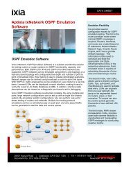
3. <strong>Testing</strong> how <strong>10</strong>GE ports handle prioritized<br />
streams based on QoS parameters<br />
Objective. To determine the maximum rate<br />
at which the DUT can forward frames<br />
correctly according to their priority<br />
settings.<br />
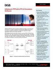
The test sets up a configuration in which<br />
many ports, each with a different priority,<br />
sends traffic to one single port. The<br />
receive port may be overloaded in order to<br />
test the receipt of the highest priority<br />
frames.<br />
This test supports both MAC and IP layer<br />
frames; priority bits may be specified<br />
either in the IP precedence bits or in the<br />
<strong>10</strong> GE<br />
1 GE<br />
1 GE<br />
802.1p header. Latency may optionally be<br />
calculated per priority level. Test results<br />
are: the transmit and receive rates per<br />
priority, percent loss, and optionally,<br />
latency, for each priority per port.<br />
Setup. A minimum of two test ports will be<br />
used for this test, in conjunction with the<br />
IxScriptmate QoS Many-to-One test. In this<br />
example, one <strong>Ixia</strong> <strong>10</strong>GE test port and two<br />
<strong>Ixia</strong> 1 GE test ports connected to the DUT –<br />
all traffic directed to a single <strong>10</strong>GE port on<br />
the DUT.<br />
Parameters. Select the three test port pairs,<br />
frame sizes, QoS parameters for each port,<br />
and number of iterations.<br />
Figure 7. <strong>Testing</strong> how <strong>10</strong>GE ports handle prioritized streams based on QoS parameters — setup.<br />
<strong>10</strong>-<strong>Gigabit</strong> <strong>Ethernet</strong> <strong>Switch</strong> <strong>Performance</strong> <strong>Testing</strong> Copyright © 2004, <strong>Ixia</strong> 25<br />
<strong>10</strong> GE
Methodology<br />
1. Packets will be sent from all ports.<br />
Multiple streams with varying QoS<br />
parameters will be sent to the one<br />
egress port.<br />
2. Total frames received, latency, and<br />
frame forwarding rate are measured<br />
per priority.<br />
3. Steps 1 and 2 continuously repeat,<br />
using selected frame sizes every<br />
interval until the test reaches the<br />
maximum frame size selected.<br />
Results. The results of the test show, on a<br />
per priority stream, the total frames<br />
received, the receive rate, and percentage<br />
loss for each frame size.<br />
Figure 8. <strong>Testing</strong> how <strong>10</strong>GE ports handle prioritized streams based on QoS parameters — results.<br />
26 Copyright © 2004, <strong>Ixia</strong> <strong>10</strong>-<strong>Gigabit</strong> <strong>Ethernet</strong> <strong>Switch</strong> <strong>Performance</strong> <strong>Testing</strong>
4. <strong>10</strong>GE OSPF Convergence Test<br />
Objective. Verify the ability of a router to<br />
switch between preferred and lesspreferred<br />
routes on its <strong>10</strong>GE ports when<br />
the preferred routes are withdrawn and readvertised.<br />
This will test the control plane<br />
function on the DUT’s <strong>10</strong>GE line card.<br />
In this test, two <strong>10</strong>GE ports simulate OSPF<br />
routers, Router 1 and Router 2. Both<br />
routers advertise the same route prefixes<br />
to the simulated network. However, the<br />
routes advertised by Router 1 will have<br />
smaller metrics (lower costs), which should<br />
cause the DUT to forward traffic over them<br />
instead of Router 2’s routes. After<br />
advertising the routes, the transmit port<br />
begins transmitting a stream of packets to<br />
an address in each of the advertised route<br />
prefixes. The DUT should forward all the<br />
packets over the route with the lower<br />
metric (Router 1). After a time interval has<br />
Figure 9. <strong>10</strong>GE OSPF Convergence Test — setup.<br />
elapsed, the receive port simulating<br />
Router 1 withdraws its routes. The DUT<br />
should detect that the preferred route has<br />
gone down and switch traffic to Router 2’s<br />
routes. Router 1 then re-advertises its<br />
routes. The DUT should again detect a<br />
change re-route traffic to the receive port<br />
simulating Router 1.<br />
Setup. This test uses three test ports — one<br />
to transmit and two to receive (see Figure<br />
9 below). One <strong>Ixia</strong> test port (acting as the<br />
transmit port) and two <strong>Ixia</strong> <strong>10</strong>GE (test<br />
ports 1 and 2 acting as receive ports)<br />
connect to the DUT. Receive ports will<br />
emulate OSPF routers. The traffic is<br />
unidirectional. The DUT must have three<br />
ports utilized with two enabled for OSPF. All<br />
three ports should be configured for IP and<br />
have unique subnets in which to<br />
communicate with the tester ports.<br />
<strong>10</strong>-<strong>Gigabit</strong> <strong>Ethernet</strong> <strong>Switch</strong> <strong>Performance</strong> <strong>Testing</strong> Copyright © 2004, <strong>Ixia</strong> 27
Results. The test results provide an average<br />
convergence time for all routes. Figure <strong>10</strong><br />
below displays example results for the<br />
automated OSPF convergence test in<br />
Figure <strong>10</strong>. <strong>10</strong>GE OSPF Convergence Test — results.<br />
IxScriptMate. In addition to convergence<br />
time, this test also indicates the amount of<br />
lost packets caused by the convergence.<br />
28 Copyright © 2004, <strong>Ixia</strong> <strong>10</strong>-<strong>Gigabit</strong> <strong>Ethernet</strong> <strong>Switch</strong> <strong>Performance</strong> <strong>Testing</strong>
Glossary<br />
Access Control List (ACL) A list of the services available on a server, each with a<br />
list of the hosts permitted to use the service.<br />
Context Memory Context memory contains instructions about whether<br />
to deny or forward a packet, where to forward and all<br />
internal system headers needed to get a packet from<br />
an ingress to egress port and the external packet<br />
header (new MAC, IP, MPLS stacks, etc.).<br />
Head-of-Line (HOL) Blocking HOL blocking occurs when the packet at the head of a<br />
queue cannot be transmitted to an output due to a<br />
contending packet from another input. At the same<br />
time, a packet further back in the queue is blocked<br />
although its destination port is free to receive the<br />
packet.<br />
Packet Buffer A temporary repository for arriving packets while they<br />
wait to be processed.<br />
Packet Processor Optimized application-specific integrated circuit (ASIC)<br />
or programmable device (NPU) for processing and<br />
forwarding packets in the data plane or fast path. It<br />
performs specific key tasks such as parsing the<br />
header, pattern matching or classification, table lookups,<br />
packet modification, and packet forwarding,<br />
ideally at wire speed.<br />
Random Early Detection (RED) Random Early Detection (RED) is a mechanism for<br />
avoiding congestion in packet switched networks. RED<br />
controls the average queue size by indicating to the<br />
end hosts when they should temporarily stop sending<br />
packets.<br />
Synchronized Digital Hierarchy<br />
(SDH)<br />
Synchronized Optical Network<br />
(SONET)<br />
SERDES Serializer/Deserializer.<br />
<strong>Switch</strong> Fabric Provides data plane interconnection between each line<br />
card in the system. The switch fabric typically employs<br />
a crossbar to move packets between its ingress and<br />
egress ports.<br />
An international digital telecommunications network<br />
hierarchy that standardizes transmission around the<br />
bit rate of 51.84 megabits per second, which is also<br />
called STS-1. The SDH specifies how payload data is<br />
framed and transported synchronously across optical<br />
fiber transmission links, without requiring all the links<br />
and nodes to have the same synchronized clock for<br />
data transmission and recovery.<br />
SONET is a standard for optical transport. It allows<br />
different types of formats to be transmitted on one<br />
line.<br />
<strong>10</strong>-<strong>Gigabit</strong> <strong>Ethernet</strong> <strong>Switch</strong> <strong>Performance</strong> <strong>Testing</strong> Copyright © 2004, <strong>Ixia</strong> 29
Ternary Content Addressable<br />
Memory (TCAM)<br />
Acknowledgements Authors: Ted Fornoles, Alireza Safari<br />
Editor, Illustrator: Elliott Stewart<br />
Content addressable memory refers to a kind of<br />
storage device that includes comparison logic with<br />
each bit of storage.<br />
Time Division Multiplexing (TDM) A method of putting multiple data streams in a single<br />
signal by separating the signal into many segments,<br />
each having a very short duration. Each individual data<br />
stream is reassembled at the receiving end.<br />
Traffic Management Function The traffic management function is used to regulate<br />
the flow of traffic. It will forward traffic according to a<br />
user-defined set of rules pertaining to priority levels,<br />
latency and bandwidth guarantees, and varying<br />
congestion levels. It also provides the necessary<br />
buffering required to work in conjunction with any<br />
queuing mechanisms it uses to manage traffic flow<br />
across the switch fabric.<br />
Wave Division Multiplexing<br />
(WDM)<br />
A type of multiplexing developed for use on optical<br />
fiber. WDM modulates each of several data streams<br />
onto a different part of the light spectrum.<br />
Weighted Fair Queuing (WFQ) A scheduling algorithm that identifies conversations (in<br />
the form of traffic streams), separates packets that<br />
belong to each conversation, and ensures that<br />
capacity is shared fairly between these individual<br />
conversations. WFQ is an automatic way of stabilizing<br />
network behavior during congestion and results in<br />
increased performance and reduced retransmission.<br />
Weighted Random Early<br />
Detection (WRED)<br />
Cisco’s implementation of RED, called Weighted<br />
Random Early Detection (WRED), combines the<br />
capabilities of the RED algorithm with IP Precedence to<br />
provide preferential traffic handling for higher priority<br />
packets.<br />
Weighted Round Robin (WRR) A scheduling algorithm that assigns a weight to each<br />
client (it can be a labeled stream or a port within a<br />
switch/hub, or a group of streams belonging to the<br />
same service level); the assigned weight corresponds<br />
to the pre-assigned bandwidth allocation for the client.<br />
30 Copyright © 2004, <strong>Ixia</strong> <strong>10</strong>-<strong>Gigabit</strong> <strong>Ethernet</strong> <strong>Switch</strong> <strong>Performance</strong> <strong>Testing</strong>