Instruction Manual - Bushnell
Instruction Manual - Bushnell
Instruction Manual - Bushnell

Create successful ePaper yourself
Turn your PDF publications into a flip-book with our unique Google optimized e-Paper software.
6.<br />
No tools are required for assembly of your telescope.<br />
DETAILED ASSEMBLY<br />
Remove all components from the carton and identify all components. It is a good idea to lay all the parts out in front of<br />
you before assembly. Since your telescope is a precision optical system the parts require careful handling—particularly<br />
the onboard computer, telescope, eyepieces, and various accessory lenses.<br />
SET UP TRIPOD AND A C C E S S O RY T R AY<br />
1. Stand Northstar Computerized Star Locator Assembly and attached tripod legs in<br />
the upright position. Spread tripod legs to a comfortable distance.<br />
2. Fold down the accessory tray braces and place the Quick Release Accessory<br />
Tray on top of braces. (See Quick Assembly Diagram)<br />
3. Turn accessory tray until it snaps into place.<br />
4. Adjust tripod leg height to suit by opening tripod leg lever and extending tripod legs<br />
to desired height. Clamp Tripod Leg lever closed when complete.<br />
1. Locate Main Telescope Tube.<br />
AT TACH TELESCOPE TUBE<br />
2. Remove Telescope Tube Thumb Nuts from side of Telescope Tube.<br />
(See Quick Assembly Diagram)<br />
3. Position Main Telescope Tube Attachment Bolts through Telescope Tube Bracket at the top of the Northstar<br />
Computerized Star Locator A s s e m b l y. Make sure the telescope is pointing in the correct direction. (Logo on<br />
telescope tube should be right-side up.)<br />
4. Reattach Telescope Tube Thumb Nuts to Main Telescope Tube Attachment Bolts once Main Telescope Tube and<br />
Northstar Computerized Star Locator Assembly are assembled together.<br />
1. Locate Red Dot Finderscope.<br />
AT TACH FINAL TELESCOPE A C C E S S O R I E S<br />
For Reflector Te l e s c o p e s :Remove Finderscope attachment nuts from Main Telescope Tube. Place Finderscope<br />
Assembly over Finderscope Attachment Bolts and reattach Finderscope thumb nuts to Finderscope Mount Bolts.<br />
N O T E : The large end of the finderscope should face the open end of telescope tube.<br />
2. Attach Low Power Eyepiece.<br />
For Reflector Telescope Models: Insert lowest power eyepiece in the focusing mechanism by backing out<br />
eyepiece set screw and inserting eyepiece fully.<br />
3. Tighten all set screws to secure accessories.<br />
4. Remove Objective Dust Cover exposing entire diameter of open end of telescope.<br />
SELECTING AN EYEPIECE<br />
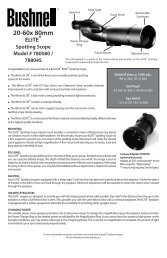
You should always start viewing with the lowest power eyepiece, which in this case is the 20 mm lens. Note: the base<br />
power of each eyepiece is determined by the focal length of the telescope objective lens. A formula can be used to<br />
determine the power of each eyepiece: telescope OBJECTIVE lens focal length divided by EYEPIECE focal length =<br />
M A G N I F I C ATION (e.g. Using the 20 mm lens, a sample calculation could look like this: 750 mm / 20 = 38x or 38<br />
p o w e r. Telescope models will vary in focal length.)<br />
Included with this telescope is a Barlow lens. Barlow lenses are used to double or triple the power of your telescope.<br />
Place your Barlow between the focusing tube and the eyepiece. Using the example above, your 3x Barlow lens would<br />
give you a total power of 114x or 114 power. (38 x 3 = 114x or 114 power). The magnification calculation would look like<br />
this: 750 mm /20mm = 38 power. 38 power x 3=114 power.