

Analytic Hypersonic Aerodynamics for Conceptual Design of Entry ...
Analytic Hypersonic Aerodynamics for Conceptual Design of Entry ...
Analytic Hypersonic Aerodynamics for Conceptual Design of Entry ...

You also want an ePaper? Increase the reach of your titles
YUMPU automatically turns print PDFs into web optimized ePapers that Google loves.
C l<br />
0.5<br />
0.4<br />
0.3<br />
0.2<br />
0.1<br />
0<br />
−0.1<br />
−0.2<br />
−0.3<br />
−0.4<br />
−0.5<br />
0 20 40 60<br />
α, deg<br />
C m<br />
1<br />
0.8<br />
0.6<br />
0.4<br />
0.2<br />
0<br />
−0.2<br />
−0.4<br />
−0.6<br />
0 20 40 60<br />
α, deg<br />
C n<br />
0.4<br />
0.3<br />
0.2<br />
0.1<br />
0<br />
−0.1<br />
−0.2<br />
−0.3<br />
−0.4<br />
0 20 40 60<br />
α, deg<br />
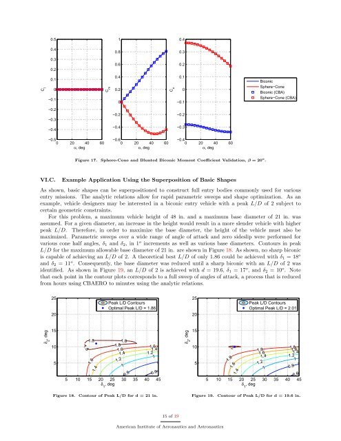
Figure 17. Sphere-Cone and Blunted Biconic Moment Coefficient Validation, β = 20 o .<br />
VI.C. Example Application Using the Superposition <strong>of</strong> Basic Shapes<br />
Biconic<br />
Sphere−Cone<br />
Biconic (CBA)<br />
Sphere−Cone (CBA)<br />
As shown, basic shapes can be superpositioned to construct full entry bodies commonly used <strong>for</strong> various<br />
entry missions. The analytic relations allow <strong>for</strong> rapid parametric sweeps and shape optimization. As an<br />
example, vehicle designers may be interested in a biconic entry vehicle with a peak L/D <strong>of</strong> 2 subject to<br />
certain geometric constraints.<br />
For this problem, a maximum vehicle height <strong>of</strong> 48 in. and a maximum base diameter <strong>of</strong> 21 in. was<br />
assumed. For a given diameter, an increase in the height would result in a more slender vehicle with higher<br />
peak L/D. There<strong>for</strong>e, in order to maximize the base diameter, the height <strong>of</strong> the vehicle must also be<br />
maximized. Parametric sweeps over a wide range <strong>of</strong> angle <strong>of</strong> attack and zero sideslip were per<strong>for</strong>med <strong>for</strong><br />
various cone half angles, δ1 and δ2, in 1 o increments as well as various base diameters. Contours in peak<br />
L/D <strong>for</strong> the maximum allowable base diameter <strong>of</strong> 21 in. are shown in Figure 18. As shown, no sharp biconic<br />
is capable <strong>of</strong> achieving an L/D <strong>of</strong> 2. A theoretical best L/D <strong>of</strong> only 1.86 could be achieved with δ1 = 18 o<br />
and δ2 = 11 o . Consequently, the base diameter was reduced until a sharp biconic with an L/D <strong>of</strong> 2 was<br />
identified. As shown in Figure 19, an L/D <strong>of</strong> 2 is achieved with d = 19.6, δ1 = 17 o , and δ2 = 10 o . Note<br />
that each point in the contour plots corresponds to a full sweep <strong>of</strong> angles <strong>of</strong> attack, a process that is reduced<br />
from hours using CBAERO to minutes using the analytic relations.<br />
δ 2 , deg<br />
25<br />
20<br />
15<br />
10<br />
5<br />
1.8<br />
1.81.8<br />
1.6<br />
1.4<br />
Peak L/D Contours<br />
Optimal Peak L/D = 1.86<br />
1.8<br />
1.61.6<br />
1.2<br />
1<br />
0.8<br />
1.2<br />
1.41.4<br />
1<br />
0.6<br />
5 10 15 20 25 30 35 40 45<br />
δ , deg<br />
1<br />
Figure 18. Contour <strong>of</strong> Peak L/D <strong>for</strong> d = 21 in.<br />
15 <strong>of</strong> 19<br />
δ 2 , deg<br />
American Institute <strong>of</strong> Aeronautics and Astronautics<br />
25<br />
20<br />
15<br />
10<br />
5<br />
2<br />
1.8<br />
1.6<br />
1.4<br />
Peak L/D Contours<br />
Optimal Peak L/D = 2.01<br />
1.8<br />
1.61.6<br />
1.2<br />
1<br />
1.8<br />
1.2<br />
1.41.4<br />
0.8<br />
1<br />
0.6<br />
5 10 15 20 25 30 35 40 45<br />
δ , deg<br />
1<br />
Figure 19. Contour <strong>of</strong> Peak L/D <strong>for</strong> d = 19.6 in.


