Analytic Hypersonic Aerodynamics for Conceptual Design of Entry ...
Analytic Hypersonic Aerodynamics for Conceptual Design of Entry ...
Analytic Hypersonic Aerodynamics for Conceptual Design of Entry ...
You also want an ePaper? Increase the reach of your titles
YUMPU automatically turns print PDFs into web optimized ePapers that Google loves.
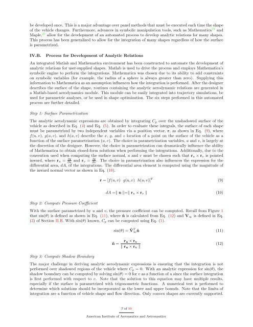
e developed once. This is a major advantage over panel methods that must be executed each time the shape<br />
<strong>of</strong> the vehicle changes. Furthermore, advances in symbolic manipulation tools, such as Mathematica 24 and<br />
Maple, 25 allow <strong>for</strong> the development <strong>of</strong> an automated process to develop analytic relations <strong>for</strong> many shapes.<br />
This process has been generalized to allow <strong>for</strong> the integration <strong>of</strong> many shapes regardless <strong>of</strong> how the surface<br />
is parametrized.<br />
IV.B. Process <strong>for</strong> Development <strong>of</strong> <strong>Analytic</strong> Relations<br />
An integrated Matlab and Mathematica environment has been constructed to automate the development <strong>of</strong><br />
analytic relations <strong>for</strong> user-supplied shapes. Matlab is used to drive the process and employs Mathematica’s<br />
symbolic engine to per<strong>for</strong>m the integrations. Mathematica was chosen due to its ability to add constraints<br />
on symbolic variables (<strong>for</strong> example, the radius <strong>of</strong> a sphere is always greater than zero). Supplying this<br />
in<strong>for</strong>mation to Mathematica as an assumption influences how the integration is per<strong>for</strong>med. After the designer<br />
describes the surface <strong>of</strong> the shape, routines containing the analytic aerodynamic relations are generated in<br />
a Matlab-based aerodynamics module. This module can be easily integrated into trajectory simulations, be<br />
used <strong>for</strong> parametric analyses, or be used in shape optimization. The six steps per<strong>for</strong>med in this automated<br />
process are further detailed.<br />
Step 1: Surface Parametrization<br />
The analytic aerodynamic expressions are obtained by integrating Cp over the unshadowed surface <strong>of</strong> the<br />
vehicle as described in Eq. (4) and Eq. (5). In order to evaluate these integrals, the surface <strong>of</strong> each shape<br />
must be parametrized by two independent variables via a position vector, r, as shown in Eq. (9), where<br />
f(u, v), g(u, v), and h(u, v) describe the x, y, and z location <strong>of</strong> a point on the surface <strong>of</strong> the vehicle as a<br />
function <strong>of</strong> the surface parametrization (u, v). The choice in parametrization variables, u and v, is largely at<br />
the discretion <strong>of</strong> the designer. However, the choice in parametrization can dramatically influence the ability<br />
<strong>of</strong> Mathematica to obtain closed-<strong>for</strong>m solutions when per<strong>for</strong>ming the integrations. Additionally, due to the<br />
convention used when computing the surface normal, u and v must be chosen such that ru × rv is pointed<br />
inward, where ru = ∂r<br />
∂u and rv = ∂r<br />
∂v<br />
. The choice in parametrization also influences the expression <strong>for</strong> the<br />
differential area, dA, <strong>of</strong> the integrations. The differential area element is computed using the magnitude <strong>of</strong><br />
the inward normal vector as shown in Eq. (10).<br />
Step 2: Compute Pressure Coefficient<br />
r = [f(u, v) g(u, v) h(u, v)] T<br />
dA = n = ru × rv (10)<br />
With the surface parametrized by u and v, the pressure coefficient can be computed. Recall from Figure 1<br />
that sin(θ) is defined as shown in Eq. (11), where ˆn is calculated from Eq. (12) and V∞ is defined in Eq.<br />
(3) <strong>of</strong> Section II.B. With sin(θ) known, Cp can be computed using Eq. (1).<br />
Step 3: Compute Shadow Boundary<br />
sin(θ) = ˆV T ∞ˆn (11)<br />
ˆn = ru × rv<br />
ru × rv <br />
The major challenge in deriving analytic aerodynamic expressions is ensuring that the integration is not<br />
per<strong>for</strong>med over shadowed regions <strong>of</strong> the vehicle where Cp = 0. With an analytic expression <strong>for</strong> sin(θ), the<br />
shadow boundary can be computed by solving sin(θ) = 0 <strong>for</strong> v as a function <strong>of</strong> u since the surface integration<br />
is first per<strong>for</strong>med with respect to v. Note that the solution to this equation may have multiple results,<br />
especially if the surface is parametrized with trigonometric functions. A numerical test is per<strong>for</strong>med to<br />
determine which solutions should be incorporated as the lower and upper bounds. Note that the limits <strong>of</strong><br />
integration are a function <strong>of</strong> vehicle shape and flow direction. Only convex shapes are currently supported.<br />
7 <strong>of</strong> 19<br />
American Institute <strong>of</strong> Aeronautics and Astronautics<br />
(9)<br />
(12)


