Hi-4 single fire motorcycle ignition - Crane Cams
Hi-4 single fire motorcycle ignition - Crane Cams
Hi-4 single fire motorcycle ignition - Crane Cams

Create successful ePaper yourself
Turn your PDF publications into a flip-book with our unique Google optimized e-Paper software.
2/05<br />
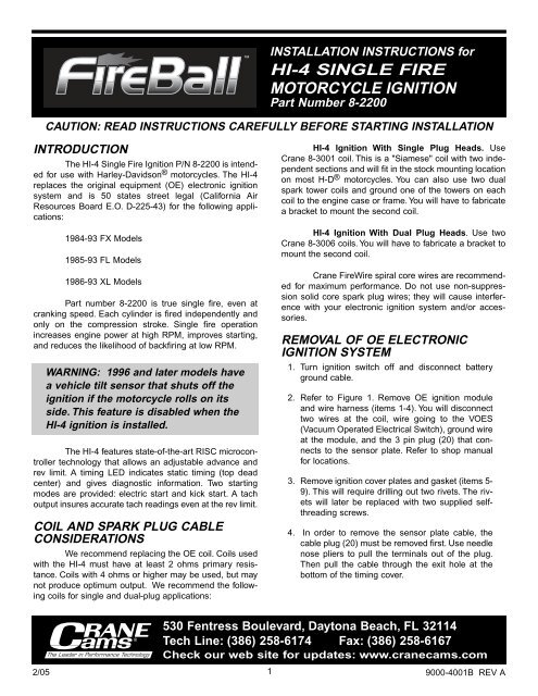
CAUTION: READ INSTRUCTIONS CAREFULLY BEFORE STARTING INSTALLATION<br />
INTRODUCTION<br />
The HI-4 Single Fire Ignition P/N 8-2200 is intended<br />
for use with Harley-Davidson ® <strong>motorcycle</strong>s. The HI-4<br />
replaces the original equipment (OE) electronic <strong>ignition</strong><br />
system and is 50 states street legal (California Air<br />
Resources Board E.O. D-225-43) for the following applications:<br />
1984-93 FX Models<br />
1985-93 FL Models<br />
1986-93 XL Models<br />
Part number 8-2200 is true <strong>single</strong> <strong>fire</strong>, even at<br />
cranking speed. Each cylinder is <strong>fire</strong>d independently and<br />
only on the compression stroke. Single <strong>fire</strong> operation<br />
increases engine power at high RPM, improves starting,<br />
and reduces the likelihood of backfiring at low RPM.<br />
WARNING: 1996 and later models have<br />
a vehicle tilt sensor that shuts off the<br />
<strong>ignition</strong> if the <strong>motorcycle</strong> rolls on its<br />
side. This feature is disabled when the<br />
HI-4 <strong>ignition</strong> is installed.<br />
The HI-4 features state-of-the-art RISC microcontroller<br />
technology that allows an adjustable advance and<br />
rev limit. A timing LED indicates static timing (top dead<br />
center) and gives diagnostic information. Two starting<br />
modes are provided: electric start and kick start. A tach<br />
output insures accurate tach readings even at the rev limit.<br />
COIL AND SPARK PLUG CABLE<br />
CONSIDERATIONS<br />
We recommend replacing the OE coil. Coils used<br />
with the HI-4 must have at least 2 ohms primary resistance.<br />
Coils with 4 ohms or higher may be used, but may<br />
not produce optimum output. We recommend the following<br />
coils for <strong>single</strong> and dual-plug applications:<br />
INSTALLATION INSTRUCTIONS for<br />
HI-4 SINGLE FIRE<br />
MOTORCYCLE IGNITION<br />
Part Number 8-2200<br />
1<br />
HI-4 Ignition With Single Plug Heads. Use<br />
<strong>Crane</strong> 8-3001 coil. This is a "Siamese" coil with two independent<br />
sections and will fit in the stock mounting location<br />
on most H-D ® <strong>motorcycle</strong>s. You can also use two dual<br />
spark tower coils and ground one of the towers on each<br />
coil to the engine case or frame. You will have to fabricate<br />
a bracket to mount the second coil.<br />
HI-4 Ignition With Dual Plug Heads. Use two<br />
<strong>Crane</strong> 8-3006 coils. You will have to fabricate a bracket to<br />
mount the second coil.<br />
<strong>Crane</strong> FireWire spiral core wires are recommended<br />
for maximum performance. Do not use non-suppression<br />
solid core spark plug wires; they will cause interference<br />
with your electronic <strong>ignition</strong> system and/or accessories.<br />
REMOVAL OF OE ELECTRONIC<br />
IGNITION SYSTEM<br />
1. Turn <strong>ignition</strong> switch off and disconnect battery<br />
ground cable.<br />
2. Refer to Figure 1. Remove OE <strong>ignition</strong> module<br />
and wire harness (items 1-4). You will disconnect<br />
two wires at the coil, wire going to the VOES<br />
(Vacuum Operated Electrical Switch), ground wire<br />
at the module, and the 3 pin plug (20) that connects<br />
to the sensor plate. Refer to shop manual<br />
for locations.<br />
3. Remove <strong>ignition</strong> cover plates and gasket (items 5-<br />
9). This will require drilling out two rivets. The rivets<br />
will later be replaced with two supplied selfthreading<br />
screws.<br />
4. In order to remove the sensor plate cable, the<br />
cable plug (20) must be removed first. Use needle<br />
nose pliers to pull the terminals out of the plug.<br />
Then pull the cable through the exit hole at the<br />
bottom of the timing cover.<br />
530 Fentress Boulevard, Daytona Beach, FL 32114<br />
Tech Line: (386) 258-6174 Fax: (386) 258-6167<br />
Check our web site for updates: www.cranecams.com<br />
9000-4001B REV A
5. Note location of sensor plate (11). There is a V<br />
notch in the sensor plate used for alignment.<br />
When you install the HI-4, you should align the V<br />
notch in the same location. This should set the<br />
timing close enough to start the engine. Remove<br />
and save the two standoffs and washers (10).<br />
Remove the sensor plate (11).<br />
HI-4 INSTALLATION<br />
Refer to Figure 2. The HI-4 requires use of the OE<br />
timing rotor P/N 32402-83. Check your rotor (9) and verify<br />
that it is the correct part number.<br />
1. Install HI-4 system in place of OE sensor plate.<br />
Rotate the HI-4 about 90 degrees to give better<br />
access to the cable exit hole. Install the HI-4 first,<br />
then push the cable through the hole. Align the V<br />
notch on the HI-4 identically to the OE plate you<br />
removed. Use the OE standoffs to secure the<br />
HI-4. You must use lockwashers under the stand-<br />
2/05<br />
Figure 1. Harley-Davidson ® 1980 and Later OE Electronic System<br />
1. Screws (2)<br />
13. Rotor<br />
2. Washers (2) 14. Gear Case<br />
3. Ignition Module<br />
Cover<br />
4. Well Nuts (2) 15. Ignition Coil<br />
5. Rivets (2)<br />
16. Ignition Coil<br />
Terminal<br />
6. Outer Cover<br />
7. Inner Cover Screws (2)<br />
8. Inner Cover<br />
9. Gasket<br />
10. Sensor Plate Screws<br />
& Washers (2 each)<br />
11. Sensor Plate<br />
15<br />
12. Rotor Screw & Star<br />
Washer<br />
14<br />
13<br />
12<br />
11<br />
17. Spark Plug Wires (2)<br />
18. Vacuum Operated<br />
Electrical Switch (VOES)<br />
19. VOES Connector<br />
20. Sensor Connector<br />
10<br />
2<br />
9<br />
16<br />
8<br />
17<br />
20<br />
offs for proper clearance between the HI-4 and<br />
cover plate. Do not fully tighten the standoffs until<br />
the timing has been set.<br />
2. Route the HI-4 wire harness along the frame rails<br />
up to the coil. Make sure that the harness will not<br />
be chafed or burned by exhaust heat. Secure harness<br />
with tie wraps. Do not install timing cover.<br />
HI-4 HOOKUP<br />
7<br />
6<br />
5<br />
Crimp terminals and hardware are supplied for your convenience.<br />
Use the ring terminals for coil hookup. Use<br />
male-female quick disconnects for connections to the tach<br />
and vacuum switch (VOES). Tape up the tach wire if<br />
unused. Self-threading screws are supplied to reinstall the<br />
outer timing cover.<br />
NOTE: Damage will result if the brown<br />
tach wire comes in contact with +12V.<br />
4<br />
18<br />
3<br />
19<br />
2<br />
9000-4001B REV A<br />
1
1. Identify switched +12 volt wire and tach wire (if<br />
equipped) going to the coil. Refer to your service<br />
manual, or reconnect the battery and use a test<br />
light or voltmeter. The switched +12 volt wire will<br />
be hot when the <strong>ignition</strong> key is turned on.<br />
2. Refer to Figure 3 or 4, depending on your application.<br />
Connect the HI-4 red wire and switched +12<br />
volt wire to Coil positive.<br />
3. Connect the HI-4 black wire to one coil negative<br />
terminal for the front cylinder.<br />
4. Connect the HI-4 white wire to the other coil negative<br />
terminal for the rear cylinder.<br />
5. Connect the HI-4 green wire to the VOES (Figure<br />
1, item 18,19).<br />
6. Connect the HI-4 brown wire to the tach wire, if<br />
equipped with tach. Tape up if unused.<br />
7. The HI-4 is grounded via the timing housing; a<br />
separate ground connection is not required.<br />
2/05<br />
NOTE: Most <strong>motorcycle</strong> coils do not<br />
have terminals marked. Most <strong>single</strong><strong>fire</strong><br />
coils use the center terminal for<br />
+12V and the outer two terminals for<br />
front and rear cylinder Coil –. For<br />
dual-<strong>fire</strong> coils use either terminal for<br />
Coil + (positive) and the other one for<br />
Coil – (negative).<br />
10<br />
Figure 2. HI-4 Ignition System Installation<br />
9<br />
8<br />
7<br />
HI-4<br />
Unit<br />
MIN<br />
4000<br />
SPKADV<br />
6000<br />
REVLIM<br />
0 0<br />
MAX<br />
8000<br />
-5 0 +5 0<br />
RACEONLY<br />
KICKSTART<br />
SINGLEFIRERACEIGNITION8-2100<br />
ALLOEPOINTS<br />
ELECSTART<br />
TIMINGLED<br />
HI-4<br />
Use Supplied<br />
Gasket<br />
3<br />
1. Buttonhead Screws (2)<br />
2. Outer Cover<br />
3. Inner Cover Screws (2)<br />
4. Inner Cover<br />
6<br />
8. Reconnect battery ground cable. Verify proper<br />
ground connections to the frame and engine.<br />
VOES HOOKUP<br />
5<br />
5. Gasket<br />
6. Sensor Plate Screws &<br />
Washers (2 each)<br />
7. HI-4 Unit<br />
8. Rotor Screw & Star Washer<br />
9. Rotor<br />
10. Gear Case Cover<br />
4<br />
3 2<br />
The OE vacuum switch (VOES) is normally an open circuit.<br />
Above 3-5 inch-Hg vacuum, the VOES closes and<br />
grounds the vacuum input on the OE <strong>ignition</strong> module. This<br />
increases the total advance generated by the <strong>ignition</strong><br />
module. Vacuum advance improves part throttle driveability<br />
and fuel economy.<br />
NOTE: 1996 and later models use a 2wire<br />
connector between the VOES and<br />
the OE harness. Connect one wire<br />
from the VOES switch to frame ground<br />
and connect the other wire to the VOES<br />
input (green wire) on the HI-4 harness.<br />
The 8-2200 HI-4 must be used with a VOES. If<br />
your <strong>motorcycle</strong> does not have a VOES, retrofit the <strong>motorcycle</strong><br />
with the H-D ® VOES P/N 26566-91.<br />
WARNING: Make sure that the VOES is<br />
connected and functioning properly<br />
prior to setting the timing.<br />
HI-4 SETUP AND OPERATION<br />
Refer to the label on the HI-4. The unit has two<br />
DIP switches that select the advance curve and starting<br />
mode. The top switch sets the advance curve. Select BIG<br />
9000-4001B REV A<br />
1
2/05<br />
GROUND<br />
TRIMPOTS<br />
DIP<br />
SWITCHES<br />
Figure 3. HI-4 Single Fire System Hookup with Single Plug Heads<br />
IGNITION<br />
SWITCH<br />
+12V<br />
–+<br />
12 VOLT<br />
BATTERY<br />
HI-4 IGNITION<br />
SPK<br />
ADV<br />
MIN MAX<br />
6000<br />
REV<br />
LIM<br />
4000 8000<br />
OTHER<br />
ENG<br />
KICK<br />
START<br />
SINGLE FIRE IGNITION 8-2200<br />
CARB E.O. D - 225-43<br />
BIG<br />
TWIN<br />
ELEC<br />
START<br />
O.E. WHITE WIRE<br />
TO COIL +<br />
TIMING<br />
LED<br />
HI-4<br />
NOTE:<br />
BLACK<br />
RED<br />
TO IGNITION SWITCH<br />
HI-4 RED WIRE<br />
WHITE<br />
4<br />
ALTERNATE HOOKUP USING TWO DUAL TOWER COILS<br />
HI-4 BLACK WIRE<br />
IGNITION<br />
COIL<br />
IGNITION<br />
COIL<br />
CRANE 8-3001<br />
SINGLE FIRE COIL<br />
BROWN<br />
GREEN<br />
HI-4 WHITE WIRE<br />
If TACH is not used, tape up the brown wire.<br />
RPMX100<br />
FRONT COIL<br />
REAR COIL<br />
FRONT<br />
SPARK PLUG<br />
REAR<br />
SPARK PLUG<br />
FRONT<br />
SPARK PLUG<br />
REAR<br />
SPARK PLUG<br />
VOES SWITCH<br />
9000-4001B REV A
2/05<br />
GROUND<br />
TRIMPOTS<br />
DIP<br />
SWITCHES<br />
IGNITION<br />
SWITCH<br />
–+<br />
Figure 4. HI-4 Single Fire System Hookup with Dual Plug Heads<br />
+12V<br />
12 VOLT<br />
BATTERY<br />
HI-4 IGNITION<br />
SPK<br />
ADV<br />
MIN MAX<br />
6000<br />
REV<br />
LIM<br />
4000 8000<br />
OTHER<br />
ENG<br />
KICK<br />
START<br />
O.E. WHITE WIRE<br />
TO COIL +<br />
SINGLE FIRE IGNITION 8-2200<br />
CARB E.O. D - 225-43<br />
BIG<br />
TWIN<br />
ELEC<br />
START<br />
TIMING<br />
LED<br />
HI-4<br />
BLACK<br />
NOTE:<br />
CRANE 8-3006<br />
OR SIMILAR<br />
DUAL TOWER<br />
COILS SHOWN<br />
RED<br />
5<br />
HI-4 WHITE WIRE<br />
BROWN<br />
GREEN<br />
IGNITION<br />
COIL<br />
IGNITION<br />
COIL<br />
RPMX100<br />
If TACH is not used, tape up the brown wire.<br />
FRONT COIL<br />
AND<br />
SPARK PLUGS<br />
REAR COIL<br />
AND<br />
SPARK PLUGS<br />
VOES SWITCH<br />
9000-4001B REV A
TWIN for 1340cc FX and FL models. Select OTHER for all<br />
other engine types.<br />
The bottom switch sets the starting mode. Kick<br />
start mode <strong>fire</strong>s the first cylinder for quickest starting.<br />
Electric start mode delays firing for 2-3 revolutions of the<br />
motor for smoother starts and less strain on the starter<br />
motor.<br />
Trimpots on the HI-4 allow adjustment of advance<br />
and RPM limit settings. Use the screwdriver supplied in<br />
the parts kit to adjust the trimpots. Trimpot setting is indicated<br />
by the slot that has two small dots on each side.<br />
NOTE: Each trimpot can be adjusted<br />
over a range of just under one turn. At<br />
the ends of the adjustment range,<br />
mechanical stops prevent further rotation<br />
of the trimpot. Do not attempt to<br />
turn the trimpots past their limits.<br />
The advance curve is adjustable over a limited<br />
range via the advance trimpot (SPK ADV). Advance<br />
curves are given in Figures 5 and 6. Each set of advance<br />
curves includes minimum and maximum curves. The actual<br />
advance curve will be between the minimum and maximum<br />
curves depending on advance trimpot setting.<br />
If you have a passenger or are using low octane<br />
gasoline, minimum advance will reduce spark knock.<br />
Maximum advance will give higher performance, but may<br />
require the use of high octane gasoline.<br />
The RPM limit trimpot (REV LIM) is adjustable<br />
from 4,000 to 8,000 RPM. Use a safe RPM limit for your<br />
engine.<br />
The HI-4 timing LED should light up when the <strong>ignition</strong><br />
key is turned on. The timing LED will go off when the<br />
flywheel is rotated past TDC. During cranking, the LED<br />
will blink.<br />
TIMING MARKS<br />
The TDC and advance timing marks are located<br />
on the flywheel and can be observed via an inspection<br />
hole (refer to shop manual for details). Refer to Figure 7 for<br />
typical timing marks. Early Style includes most 1980 and<br />
earlier models. Late Style includes most 1981-95 models.<br />
If the shop manual is not available, remove spark plugs,<br />
turn engine until front piston is at TDC on compression<br />
stroke and identify TDC mark on the flywheel. Refer to<br />
Figure 7 and find the diagram with a matching TDC mark.<br />
Use the corresponding advance mark shown in the diagram.<br />
NOTE: 1996 and later models (1995<br />
and later for export models) have a<br />
timing mark at 20° BTDC for setting<br />
the timing with the OE <strong>ignition</strong> module.<br />
Do not use this mark for setting the<br />
timing on the HI-4. In most cases an<br />
additional mark will remain at 35°<br />
BTDC (see Figure 7). Use this mark to<br />
set the timing with a timing light as<br />
described below.<br />
INITIAL STATIC TIMING PROCEDURE<br />
In most cases, aligning the V notch on the HI-4<br />
plate to the same location as the OE plate will set the timing<br />
close enough to start the engine. If the engine will not<br />
start or runs very rough, you can use the following static<br />
timing procedure.<br />
Remove spark plugs and turn the engine over<br />
until the TDC mark appears in the timing inspection hole<br />
(See Figure 7). Ground spark plugs with an alligator clip so<br />
you will not shock yourself. Turn on the <strong>ignition</strong> but do not<br />
start the <strong>motorcycle</strong>. Loosen the standoffs holding HI-4<br />
and rotate the unit clockwise until the timing LED goes out.<br />
The point at which the timing LED goes off is TDC. Timing<br />
is now set approximately at TDC. Turn off <strong>ignition</strong> and reinstall<br />
spark plugs. Once engine has been started, timing<br />
with a timing light is necessary.<br />
SETTING ADVANCE TIMING USING<br />
STANDARD TIMING LIGHT<br />
This timing procedure requires that a VOES<br />
switch be connected to the HI-4. Connect a timing light to<br />
the front cylinder. Set the HI-4 advance trimpot to a<br />
midrange setting. Run the engine at 2,000 to 2,200 RPM.<br />
Adjust the HI-4 module assembly in the gear cover until<br />
the advance timing mark is centered in the timing inspection<br />
hole (See Figure 7). Fasten the standoffs and verify<br />
that timing has not shifted.<br />
ADVANCE CURVE SETUP<br />
After you have set the timing as explained above,<br />
set the HI-4 advance trimpot to desired position. If you run<br />
93 octane gasoline, you can usually leave the trimpot full<br />
clockwise for maximum advance and performance, without<br />
spark knock.<br />
6<br />
2/05 9000-4001B REV A
COVER PLATE ASSEMBLY<br />
You can re-use the OE hardware, except use the<br />
supplied <strong>Crane</strong> gasket to provide proper clearance for the<br />
HI-4. Use the supplied self-threading screws in place of<br />
the rivets that held the outer cover.<br />
2/05<br />
TOTAL ADVANCE (CRANK DEGREES)<br />
TOTAL ADVANCE (CRANK DEGREES)<br />
50<br />
40<br />
30<br />
20<br />
10<br />
50<br />
40<br />
30<br />
20<br />
10<br />
0<br />
0<br />
0<br />
0<br />
1000<br />
1000<br />
Figure 5. Advance Curves for Big Twin ® Engines<br />
2000<br />
2000<br />
3000<br />
3000<br />
4000<br />
4000<br />
7<br />
5000<br />
ENGINE RPM<br />
MIN ADV/LOW VAC MAX ADV/LOW VAC MIN ADV/HIGH VAC MAX ADV/HIGH VAC<br />
5000<br />
ENGINE RPM<br />
MIN ADV/LOW VAC MAX ADV/LOW VAC MIN ADV/HIGH VAC MAX ADV/HIGH VAC<br />
6000<br />
Figure 6. Advance Curves for Other Engines<br />
6000<br />
7000<br />
7000<br />
TROUBLESHOOTING<br />
8000<br />
8000<br />
9000<br />
9000<br />
Did the engine run properly before installation of<br />
the HI-4? If not, remove the HI-4, reinstall the OE <strong>ignition</strong><br />
or another known good unit and then find and correct the<br />
original problem. Did the HI-4 function correctly before the<br />
problem occurred? If the answer is yes, did you change<br />
9000-4001B REV A
2/05<br />
Figure 7. Top Dead Center (TDC) and Front Cylinder Advance Marks for Various Models<br />
Front Cylinder TDC Mark<br />
anything that may have affected it? Try going back to the<br />
last setup that worked OK to help isolate the problem.<br />
If the engine will not start, or runs rough or intermittently,<br />
use the following checklist steps:<br />
ENGINE WILL NOT START<br />
Front Cylinder TDC Mark<br />
1. Check that timing LED lights up when <strong>ignition</strong> key<br />
is first turned on. If not, check for +12 volts on red<br />
wire from HI-4.<br />
2. Check that timing LED blinks while engine is<br />
cranked. If not, HI-4 may be defective.<br />
3. If the timing LED blinks, but engine will not start,<br />
recheck all wire harness connections or replace<br />
coil(s).<br />
4. Check for low voltage from a faulty or marginal<br />
charging system and battery.<br />
NOTE: The battery ground on most Harley-<br />
Davidsons® is connected to the frame<br />
behind the seat. In order to provide a dedicated<br />
ground for the high starter current,<br />
another cable should be installed from the<br />
point on the frame that the battery is<br />
already grounded to the starter mounting<br />
flange. This cable should be the same<br />
diameter as the battery ground cable<br />
presently on the bike, and will help prevent<br />
damage to your electronic components.<br />
8<br />
Early Style<br />
Late Style<br />
Front Cylinder Advance Mark<br />
Front Cylinder TDC Mark Front Cylinder Advance Mark<br />
1996 and Later Models (1995 and Later Export)<br />
Front Cylinder 20° Mark<br />
DO NOT USE<br />
Front Cylinder 35° Mark<br />
CHECKING FOR SPARK<br />
To crank the engine and check for spark, use a KD<br />
Tools test plug or H-D ® tool HD-26792. These test plugs<br />
come with an alligator clip that must be attached to frame<br />
or engine ground. Use a length of spark plug wire to connect<br />
the test plug to the coil.<br />
WARNING: Never crank the engine with<br />
any spark plug wire disconnected.<br />
MISFIRE OR INTERMITTENT<br />
OPERATION<br />
Field experience has shown that popping back<br />
through the carburetor, misfiring, and intermittent failure<br />
(especially after the engine gets hot) are usually not<br />
caused by electrical problems within the HI-4. Carburetor<br />
problems, fouled spark plugs, coil failure, and loose wire<br />
harness connections are the most common culprits. Verify<br />
that spiral core or suppression type spark plug wires and<br />
resistor spark plugs are being used.<br />
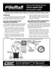
TACH INOPERATIVE<br />
If the tach is inoperative after installation of the<br />
HI-4, you may require a tach adapter. The HI-4 tach output<br />
is compatible with ground sensing tachs which includes<br />
most OE and aftermarket tachs. Some tachs require a<br />
high voltage trigger pulse. In this case, install <strong>Crane</strong> tach<br />
adapter P/N 8-2050. Note that the tach will read correctly<br />
at the rev limit only if it is connected to the brown wire from<br />
the HI-4. Damage to the HI-4 circuitry may have occurred<br />
if 12 volts was applied to the brown tach wire at any time.<br />
9000-4001B REV A