Hi-4 single fire motorcycle ignition - Crane Cams
Hi-4 single fire motorcycle ignition - Crane Cams
Hi-4 single fire motorcycle ignition - Crane Cams

Create successful ePaper yourself
Turn your PDF publications into a flip-book with our unique Google optimized e-Paper software.
1. Identify switched +12 volt wire and tach wire (if<br />
equipped) going to the coil. Refer to your service<br />
manual, or reconnect the battery and use a test<br />
light or voltmeter. The switched +12 volt wire will<br />
be hot when the <strong>ignition</strong> key is turned on.<br />
2. Refer to Figure 3 or 4, depending on your application.<br />
Connect the HI-4 red wire and switched +12<br />
volt wire to Coil positive.<br />
3. Connect the HI-4 black wire to one coil negative<br />
terminal for the front cylinder.<br />
4. Connect the HI-4 white wire to the other coil negative<br />
terminal for the rear cylinder.<br />
5. Connect the HI-4 green wire to the VOES (Figure<br />
1, item 18,19).<br />
6. Connect the HI-4 brown wire to the tach wire, if<br />
equipped with tach. Tape up if unused.<br />
7. The HI-4 is grounded via the timing housing; a<br />
separate ground connection is not required.<br />
2/05<br />
NOTE: Most <strong>motorcycle</strong> coils do not<br />
have terminals marked. Most <strong>single</strong><strong>fire</strong><br />
coils use the center terminal for<br />
+12V and the outer two terminals for<br />
front and rear cylinder Coil –. For<br />
dual-<strong>fire</strong> coils use either terminal for<br />
Coil + (positive) and the other one for<br />
Coil – (negative).<br />
10<br />
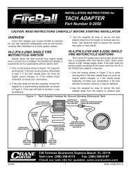
Figure 2. HI-4 Ignition System Installation<br />
9<br />
8<br />
7<br />
HI-4<br />
Unit<br />
MIN<br />
4000<br />
SPKADV<br />
6000<br />
REVLIM<br />
0 0<br />
MAX<br />
8000<br />
-5 0 +5 0<br />
RACEONLY<br />
KICKSTART<br />
SINGLEFIRERACEIGNITION8-2100<br />
ALLOEPOINTS<br />
ELECSTART<br />
TIMINGLED<br />
HI-4<br />
Use Supplied<br />
Gasket<br />
3<br />
1. Buttonhead Screws (2)<br />
2. Outer Cover<br />
3. Inner Cover Screws (2)<br />
4. Inner Cover<br />
6<br />
8. Reconnect battery ground cable. Verify proper<br />
ground connections to the frame and engine.<br />
VOES HOOKUP<br />
5<br />
5. Gasket<br />
6. Sensor Plate Screws &<br />
Washers (2 each)<br />
7. HI-4 Unit<br />
8. Rotor Screw & Star Washer<br />
9. Rotor<br />
10. Gear Case Cover<br />
4<br />
3 2<br />
The OE vacuum switch (VOES) is normally an open circuit.<br />
Above 3-5 inch-Hg vacuum, the VOES closes and<br />
grounds the vacuum input on the OE <strong>ignition</strong> module. This<br />
increases the total advance generated by the <strong>ignition</strong><br />
module. Vacuum advance improves part throttle driveability<br />
and fuel economy.<br />
NOTE: 1996 and later models use a 2wire<br />
connector between the VOES and<br />
the OE harness. Connect one wire<br />
from the VOES switch to frame ground<br />
and connect the other wire to the VOES<br />
input (green wire) on the HI-4 harness.<br />
The 8-2200 HI-4 must be used with a VOES. If<br />
your <strong>motorcycle</strong> does not have a VOES, retrofit the <strong>motorcycle</strong><br />
with the H-D ® VOES P/N 26566-91.<br />
WARNING: Make sure that the VOES is<br />
connected and functioning properly<br />
prior to setting the timing.<br />
HI-4 SETUP AND OPERATION<br />
Refer to the label on the HI-4. The unit has two<br />
DIP switches that select the advance curve and starting<br />
mode. The top switch sets the advance curve. Select BIG<br />
9000-4001B REV A<br />
1