HDL-64E Manual - Velodyne Lidar
HDL-64E Manual - Velodyne Lidar
HDL-64E Manual - Velodyne Lidar

You also want an ePaper? Increase the reach of your titles
YUMPU automatically turns print PDFs into web optimized ePapers that Google loves.
<strong>HDL</strong> -<strong>64E</strong><br />
USER’S<br />
MANUAL<br />
High Definition <strong>Lidar</strong> Sensor
Caution<br />
INVISIBLE LASER RADIATION<br />
DO NOT VIEW DIRECTLY WITH<br />
OPTICAL INSTRUMENTS<br />
CLASS 1M LASER PRODUCT<br />
.w ww.velodyne.com <strong>HDL</strong>-<strong>64E</strong> User’s <strong>Manual</strong><br />
i
Table of Contents<br />
Introduction . . . . . . . . . . . . . . . . . . . . . . . . . . . . . . . . . . . . . . . . . . . . . . . . . . . . . . .1<br />
Principles of Operation . . . . . . . . . . . . . . . . . . . . . . . . . . . . . . . . . . . . . . . . . . . . . . .2<br />
Installation Overview . . . . . . . . . . . . . . . . . . . . . . . . . . . . . . . . . . . . . . . . . . . . . . . . .3<br />
- Mounting . . . . . . . . . . . . . . . . . . . . . . . . . . . . . . . . . . . . . . . . . . . . . . . . . . . . .3<br />
- Wiring . . . . . . . . . . . . . . . . . . . . . . . . . . . . . . . . . . . . . . . . . . . . . . . . . . . . . . .6<br />
Usage . . . . . . . . . . . . . . . . . . . . . . . . . . . . . . . . . . . . . . . . . . . . . . . . . . . . . . . . . .6<br />
- Data Packet Construction . . . . . . . . . . . . . . . . . . . . . . . . . . . . . . . . . . . . . . . . . .6<br />
- Correction Angles . . . . . . . . . . . . . . . . . . . . . . . . . . . . . . . . . . . . . . . . . . . . . . . .7<br />
- Controlling the Spin Rate . . . . . . . . . . . . . . . . . . . . . . . . . . . . . . . . . . . . . . . . . . .8<br />
Firmware Update . . . . . . . . . . . . . . . . . . . . . . . . . . . . . . . . . . . . . . . . . . . . . . . . . . .8<br />
Troubleshooting . . . . . . . . . . . . . . . . . . . . . . . . . . . . . . . . . . . . . . . . . . . . . . . . . . . .9<br />
Service and Maintenance . . . . . . . . . . . . . . . . . . . . . . . . . . . . . . . . . . . . . . . . . . . . .9<br />
Specifications . . . . . . . . . . . . . . . . . . . . . . . . . . . . . . . . . . . . . . . . . . . . . . . . . . . .10<br />
Appendix A — Connector Wiring Diagram . . . . . . . . . . . . . . . . . . . . . . . . . . . . . . . . .11<br />
Appendix B — Angular Resolution . . . . . . . . . . . . . . . . . . . . . . . . . . . . . . . . . . . . . . .12<br />
Appendix C — Digital Sensor Recorder (DSR) . . . . . . . . . . . . . . . . . . . . . . . . . . . . . . .13<br />
.w ww.velodyne.com <strong>HDL</strong>-<strong>64E</strong> User’s <strong>Manual</strong><br />
ii
Introduction<br />
Congratulations on your purchase of a <strong>Velodyne</strong> <strong>HDL</strong>-<strong>64E</strong> High Definition <strong>Lidar</strong> Sensor. This<br />
product represents a breakthrough in sensing technology by providing exponentially more<br />
information about the surrounding environment than previously possible.<br />
This guide first covers installation and wiring, then addresses output packet construction and<br />
interpretation, and finally discusses the serial interface to the unit and software updates.<br />
This manual is undergoing constant revision and improvement – check<br />
www.velodyne.com/lidar for updates.<br />
Each shipment contains:<br />
• <strong>HDL</strong>-<strong>64E</strong> sensor<br />
• Wiring harness<br />
• CD with user manual, calibration file (db.XML) and DSR viewer<br />
.w ww.velodyne.com <strong>HDL</strong>-<strong>64E</strong> User’s <strong>Manual</strong><br />
1
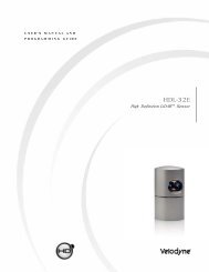
Principles of Operation<br />
The <strong>HDL</strong>-<strong>64E</strong> operates on a rather simple premise: instead of a single laser firing through a<br />
rotating mirror, 64 lasers are mounted on upper and lower blocks of 32 lasers each and the<br />
entire unit spins. This design allows for 64 separate lasers to each fire thousands of times per<br />
second, providing exponentially more data points per second and a much richer point cloud than<br />
conventional designs. The unit inherently delivers a 360-degree horizontal field of view (FOV) and<br />
a 26.8 degree vertical FOV.<br />
Additionally, state-of-the-art signal processing and waveform analysis are employed to provide<br />
high accuracy, extended distance sensing and intensity data. The <strong>HDL</strong>-<strong>64E</strong> is rated to provide<br />
usable returns up to 120 meters.<br />
Laser<br />
Emitters<br />
(Groups of 16)<br />
Laser<br />
Receivers<br />
(Groups of 32)<br />
Motor<br />
Housing<br />
Figure 1. <strong>HDL</strong>-<strong>64E</strong> design overview.<br />
The <strong>HDL</strong>-<strong>64E</strong> employs a direct drive motor system — there are no belts or chains in the<br />
drive train.<br />
.w ww.velodyne.com <strong>HDL</strong>-<strong>64E</strong> User’s <strong>Manual</strong><br />
Housing<br />
(Entire unit spins<br />
at 5-15 Hz)<br />
2
Installation Overview<br />
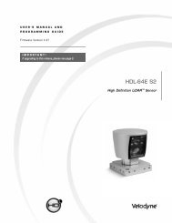
Front/Back Mounting<br />
The <strong>HDL</strong>-<strong>64E</strong> base provides two mounting options: side mount and top mount. See Figure 2<br />
for front/back mounting options, Figure 3 for side/side mounting, and Figure 4 for top<br />
mounting instructions.<br />
Figure 2. Front and back <strong>HDL</strong> mounting illustration.<br />
Mounting<br />
Base<br />
Four M8-1.25 x 12mm<br />
deep mounting points.<br />
(Four per side, for a<br />
total of 16.)<br />
See Figure 2. This figure shows the <strong>HDL</strong>-<strong>64E</strong>’s base plate screw locations with threaded inserts<br />
for standard M8 hardware.<br />
.w ww.velodyne.com <strong>HDL</strong>-<strong>64E</strong> User’s <strong>Manual</strong><br />
3
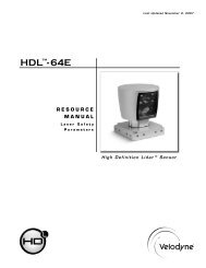
Side Mounting<br />
Figure 3. Side/side <strong>HDL</strong> mounting illustration.<br />
Mounting<br />
Base<br />
.w ww.velodyne.com <strong>HDL</strong>-<strong>64E</strong> User’s <strong>Manual</strong><br />
4
Top Mounting<br />
Figure 4. <strong>HDL</strong> top mounting illustration.<br />
Figure 4 shows the location of four .406” thru holes for top mounting.<br />
Four .406” through<br />
holes for top mount<br />
option to secure the<br />
<strong>HDL</strong> to the vehicle.<br />
For all mounting options, be sure the <strong>HDL</strong>-<strong>64E</strong> is mounted securely to withstand vibration and<br />
shock without risk of detachment. The unit need not be shock proofed — it is designed to<br />
withstand standard automotive G-forces.<br />
The <strong>HDL</strong>-<strong>64E</strong> is weatherproofed to withstand wind, rain, and other adverse weather conditions.<br />
The spinning nature of the <strong>HDL</strong>-<strong>64E</strong> helps the unit shed excess water from the front window<br />
that could hamper performance.<br />
.w ww.velodyne.com <strong>HDL</strong>-<strong>64E</strong> User’s <strong>Manual</strong><br />
5
Wiring<br />
The <strong>HDL</strong>-<strong>64E</strong> comes with a pre-wired connector, wired with power, DB9 serial, and standard<br />
RJ-45 Ethernet connectors.The connector wires are approximately 25’ in length.<br />
Power. Connect the red and black wires to vehicle power. Be sure red is positive polarity. THE<br />
<strong>HDL</strong>-<strong>64E</strong> IS RATED ONLY FOR 12 VOLTS. Any voltage applied over 16 volts could damage the<br />
unit. Expect the unit to draw 4-6 amps during normal usage.<br />
NOTE: The <strong>HDL</strong>-<strong>64E</strong> does not have a power switch. It spins whenever power is applied.<br />
The <strong>HDL</strong>-<strong>64E</strong> has a lockout circuit that prevents its lasers from firing at low RPMs.<br />
Ethernet. This standard Ethernet connector is designed to connect to a standard PC. See the<br />
next section on usage for UDP packet formats.<br />
Serial Interface. The connector also features an RS-232 DB9 serial connector. This connector<br />
allows for a firmware update to be applied to the <strong>HDL</strong>-<strong>64E</strong> (<strong>Velodyne</strong> may release firmware<br />
updates from time to time). It also accepts commands to change the RPM of the unit.<br />
Cable Diagram. If you wish to wire your own connector, refer to Appendix A for a layout of the<br />
wiring pins.<br />
Usage<br />
Data Packet Construction<br />
The <strong>HDL</strong>-<strong>64E</strong> outputs UDP Ethernet packets. Each packet contains a data payload of 1206<br />
bytes that consists of 12 blocks of 100-byte firing data followed by six bytes at the end of each<br />
packet that contains a spin counter and firmware version information. Each packet can be for<br />
either the upper or lower laser banks (called “laser blocks”) - each bank contains 32 lasers.<br />
The packet format is as follows:<br />
2 bytes of header info. This header indicates whether the packet is for the upper block or<br />
the lower block. The upper block will have a header of 0xEEFF and the lower block will have<br />
a header of 0xDDFF.<br />
2 bytes of rotational info. This is an integer between 0 and 35999. Divide this number<br />
by 100 to get degrees from 0.<br />
32 laser returns broken into 3 bytes each. Each return contains two bytes of distance<br />
information in .2 centimeter increments, and one byte of intensity information (0 – 255, with<br />
255 being the most intense return). A zero return indicates no return up to 65 meters.<br />
Six status bytes that alternate between packets. The end of the packet will show either:<br />
- A reading showing the internal temperature of the unit. You will see a " DegC " ASCII<br />
string as the last four bytes of the packet. The two bytes before this string are the<br />
thermistor's reading in C in hex 8.8 format. This is in " big indian format" - i.e. the byte<br />
immediately preceding the DegC text is the whole degrees, and the byte preceding that<br />
is the fraction of a degree in 1/256 increments. So if you see c0 1a, the temperature<br />
of the thermistor is 26.75 degrees C.<br />
- Or, the version number of the firmware in ASCII character format " Vn.n" where n.n is<br />
the version number, i.e. "1.5".<br />
.w ww.velodyne.com <strong>HDL</strong>-<strong>64E</strong> User’s <strong>Manual</strong><br />
6
The <strong>HDL</strong>-<strong>64E</strong> data is presented as distances and intensities only. <strong>Velodyne</strong> includes a packet<br />
viewer called DSR, whose installer files are on the CD that came with the unit. DSR reads in<br />
the packets from the <strong>HDL</strong>-<strong>64E</strong> unit, performs the necessary calculations to plot the points<br />
presented in 3-D space, and plots the points on the viewer screen.<br />
Note: The <strong>HDL</strong>-<strong>64E</strong> will output three upper block packets for every one lower block packet.<br />
This provides more resolution when identifying objects at greater distances.<br />
The minimum return distance for the <strong>HDL</strong>-<strong>64E</strong> is approximately three feet. Returns closer<br />
than this should be ignored.<br />
Correction Angles<br />
Each <strong>HDL</strong>-<strong>64E</strong> laser is fixed with respect to vertical angle and offset to the rotational index data<br />
provided in each packet. For each data point issued by the <strong>HDL</strong>-<strong>64E</strong>, rotational and horizontal<br />
correction factors must be applied to determine the point’s location in 3-D space referred to by<br />
the return. Each <strong>HDL</strong>-<strong>64E</strong> unit comes with its own unique .XML file, called db.XML, that was<br />
generated as a result of the calibration performed at <strong>Velodyne</strong>’s factory. DSR uses this XML<br />
file to display points accurately. The .XML file also holds the key to interpreting the packet data<br />
for users that wish to create their own interpretation and plotting routines.<br />
db.XML contains 64 instances of the following five values used to interpret the packet data:<br />
rotCorrection: This parameter is the rotational correction angle for each laser, as<br />
viewed from the back of the unit. Positive factors rotate to the left, and negative<br />
values rotate to the right.<br />
vertCorrection: This parameter is the vertical correction angle for each laser, as<br />
viewed from the back of the unit. Positive values have the laser pointing up, and<br />
negative values have the laser pointing down.<br />
distCorrection: Each laser has its own unique distance due to minor variations in the<br />
parts used to construct the laser. This correction factor, in centimeters, accounts<br />
for this variance. This number should be directly added to the distance value read in<br />
the packet.<br />
vertoffsetCorrection: This value represents the height of each laser as measured<br />
from the bottom of the base. It is a fixed value for all upper block lasers and a<br />
different fixed value for all lower block lasers.<br />
horizOffsetCorrection: This value represents the horizontal offset of each laser as<br />
viewed from the back of the laser. It is a constant positive or negative value for<br />
all lasers.<br />
Use the above values from the .XML file to calculate each point’s position in 3-D space. Use the<br />
first 32 points for the upper block and the second 32 points for the lower block. The rotational<br />
info found in the header is used to determine the packets position with respect to the 360<br />
degree horizontal field of view.<br />
Note: There is a file on the CD called “<strong>HDL</strong> Source Example” that shows the calculations using<br />
the above correction factors.<br />
.w ww.velodyne.com <strong>HDL</strong>-<strong>64E</strong> User’s <strong>Manual</strong><br />
7
Controlling the Spin Rate<br />
The <strong>HDL</strong>-<strong>64E</strong> can spin at rates ranging from 300 RPM (5 Hz) to 900 RPM (15 Hz). The default<br />
is 600 RPM (10 Hz). Note that changing the spin rate does not change the data rate – the<br />
unit will send out the same number of packets (at a rate of one million data points per second)<br />
regardless of spin rate. The image resolution will increase or decrease depending on rotation<br />
speed. See Appendix B for angular resolution figures for various spin rates.<br />
To control the <strong>HDL</strong>'s spin rate, connect the serial cable to an available RS-232 COM port and<br />
issue a serial command of the format #<strong>HDL</strong>RPMnnn$ where nnn is an integer between 300<br />
and 900. The characters are case sensitive and must be CAPS. The <strong>HDL</strong>-<strong>64E</strong> will adopt the<br />
new spin rate. Use the following serial parameters: Baud 9600, Parity: None, Data bits: 8,<br />
Stop bits: 1. The <strong>HDL</strong>-<strong>64E</strong> has no echo back feature, so no serial data will be returned from<br />
the <strong>HDL</strong>-<strong>64E</strong>.<br />
Firmware Update<br />
<strong>Velodyne</strong> may issue firmware updates from time to time. To apply the update, connect the<br />
DB9 RS-232 cable to a standard Windows-compatible PC’s serial port. The <strong>HDL</strong>-<strong>64E</strong> must<br />
be powered up and spinning during the update.<br />
Execute the file supplied by <strong>Velodyne</strong> – all the software and firmware is included to update the<br />
unit. Once the file is executed, the following screen will appear:<br />
Figure 5. <strong>HDL</strong> software update<br />
screen capture.<br />
Press update and the unit will update. If the update was successful, the unit will begin to spin<br />
down for a few seconds then power back up with the new firmware running. If the first update<br />
is not successful, it is recommended to try the update again several times before seeking<br />
assistance from <strong>Velodyne</strong>.<br />
NOTE: The entire new firmware is uploaded and checksummed before being applied to the flash<br />
memory inside the <strong>HDL</strong>-<strong>64E</strong>. If the checksum is corrupted, no software update occurs. This<br />
protects the unit in the event of power or data loss during the firmware update.<br />
.w ww.velodyne.com <strong>HDL</strong>-<strong>64E</strong> User’s <strong>Manual</strong><br />
8
Troubleshooting<br />
Use this chart to troubleshoot common problems with the <strong>HDL</strong>-<strong>64E</strong>.<br />
Problem Resolution<br />
Unit doesn’t spin Verify power connection and polarity.<br />
Verify proper voltage – should be 12 volts<br />
drawing about 3-4 amps.<br />
Unit spins but no data Verify Ethernet wiring.<br />
Remove bottom cover and check inline fuse.<br />
Replace if necessary.<br />
Verify packet output from another source<br />
(e.g. Ethereal/Wireshark).<br />
No serial communication Verify RS-232 cable connection.<br />
Service and Maintenance<br />
Unit must be active and spinning for<br />
RS-232 update.<br />
It may take several tries for the update<br />
to be effective.<br />
There are no user service or maintenance requirements or procedures for the <strong>Velodyne</strong> <strong>HDL</strong>-<strong>64E</strong>.<br />
For service or maintenance, please contact <strong>Velodyne</strong> at (408) 465-2800, or log on to our<br />
website at www.velodyne.com/lidar.<br />
.w ww.velodyne.com <strong>HDL</strong>-<strong>64E</strong> User’s <strong>Manual</strong><br />
9
Specifications<br />
Sensor:<br />
Laser:<br />
Mechanical:<br />
Output:<br />
• 64 lasers/detectors<br />
• 360 degree field of view (azimuth)<br />
• 0.09 degree angular resolution (azimuth)<br />
• 26.8 degree vertical field of view (elevation) -+2° up to -24.8° down<br />
with 64 equally spaced angular subdivisions (approximately 0.4°)<br />
• 1M points per second<br />
•
Appendix A - Connector Wiring Diagram<br />
SERIAL CONNECTOR<br />
User Interface Harness<br />
ETHERNET CONNECTOR<br />
J2<br />
J1<br />
D E<br />
J F<br />
I G<br />
A H<br />
C<br />
B<br />
.w ww.velodyne.com <strong>HDL</strong>-<strong>64E</strong> User’s <strong>Manual</strong><br />
PIN 1<br />
P1<br />
KEY<br />
J1<br />
P1<br />
3<br />
1<br />
6<br />
2<br />
4<br />
5<br />
N/C<br />
CENTER CON.<br />
RED<br />
SHIELD<br />
YEL<br />
H<br />
E<br />
A<br />
D<br />
EHTERNET OUT (+)<br />
EHTERNET IN (+)<br />
EHTERNET OUT (-)<br />
EHTERNET IN (-)<br />
GND<br />
12-16VDC (+)<br />
7<br />
8<br />
N/C<br />
N/C<br />
N/C<br />
N/C<br />
N/C<br />
J2<br />
BLK<br />
RED<br />
N/C<br />
N/C<br />
N/C<br />
N/C<br />
J<br />
I<br />
G<br />
F<br />
C<br />
B<br />
P3<br />
P5<br />
11
Appendix B - Angular Resolution<br />
Lower Block<br />
RPM RPS Points Per Points Per Revolution Angular Resolution<br />
Revolution Per Laser (degrees)<br />
300 5 50000 1562.5 0.2304<br />
600 10 25000 781.25 0.4608<br />
900 15 16667 521 0.6912<br />
Upper Block<br />
RPM RPS Points Per Points Per Revolution Angular Resolution Post-Lower-Block<br />
Revolution Per Laser (degrees) Angular Resolution<br />
(degrees)**<br />
300 5 200000 6250 0.0576 0.1152<br />
600 10 100000 3125 0.1152 0.2304<br />
900 15 66667 2083 0.1728 0.3456<br />
Notes:<br />
The <strong>HDL</strong>-<strong>64E</strong> generates 1 million points per second<br />
• The lower block reports 250,000 points<br />
• The upper block reports 750,000 points<br />
There are three upper block packets then one lower block packet reported, then the pattern repeats.<br />
** The first upper block measurement after the lower block measurement reports has half the<br />
angular resolution.<br />
.w ww.velodyne.com <strong>HDL</strong>-<strong>64E</strong> User’s <strong>Manual</strong><br />
12
Appendix C - Digital Sensor Recorder (DSR)<br />
Digital Sensor Recorder (DSR)<br />
DSR is a 3-dimensional point cloud visualization software program designed for use with the<br />
<strong>HDL</strong>-<strong>64E</strong>. It can be located on the CD provided with each <strong>HDL</strong>-<strong>64E</strong> sensor. <strong>Velodyne</strong> offers this<br />
software as an “out of the box” tool for the rendering and recording of point cloud data from<br />
the <strong>HDL</strong>-<strong>64E</strong> sensor.<br />
DSR is intended as a reference platform from which the end user can author their own<br />
proprietary adaptation and visualization software packages.<br />
Note: A code snippet is provided on the same CD to aid in understanding the methods at which<br />
DSR parses the data points generated by the <strong>HDL</strong>-<strong>64E</strong> sensor.<br />
Installing DSR<br />
Locate the DSR executable program on the provided CD. Double click on “DSR-1.1-2-install<br />
3.exe” to begin the installation onto the host computer. Use of the default settings during the<br />
installation is highly recommended.<br />
When the installation is complete, follow the “Utilizing the db.xml calibration data file in DSR”<br />
instructions in the next section to calibrate the DSR viewer to your new sensor.<br />
Note: failure to use the calibration db.xml file supplied with your sensor will result in sub-optimal<br />
point cloud rendering in DSR.<br />
Using DSR<br />
DSR gives the user the ability to view point cloud data in real time or to create a recording of<br />
such data for future reference and playback. The recorded data will be stored in a standard<br />
pcap file format.<br />
Note: These files can become quite large so the user should be mindful of recording duration<br />
when created.<br />
Live Playback:<br />
For live playback, first secure and power up the <strong>HDL</strong>-<strong>64E</strong> sensor so that it is spinning. Connect<br />
the RJ45 Ethernet connector to your host computer’s network connection. You may wish to<br />
utilize auto DNS settings for your computers network configuration.<br />
DSR desktop icon =<br />
Open DSR from your desktop icon created during the installation. Pull down the “Options”<br />
menu and select the proper input device. Go to “Options” again and deselect the “Show Ground<br />
Plane” option. (Leave this feature off for the time being or until the ground plane has been<br />
properly adjusted).<br />
.w ww.velodyne.com <strong>HDL</strong>-<strong>64E</strong> User’s <strong>Manual</strong><br />
13
You can now go to “Options/Properties” to change the individual settings for each LASER<br />
channel if so desired.<br />
REFRESH button =<br />
Provided that your computer is now receiving data packets, click on the Refresh button to start<br />
live viewing of a point cloud. The initial image is of a directly overhead perspective. See page 17<br />
for mouse and key commands used to manipulate the 3D image within the viewer.<br />
Note: The image can be manipulated in all directions and become disorienting. If you lose<br />
perspective, simply press F1 to return to the original view.<br />
Recording Data:<br />
RECORD button =<br />
Once the input of streaming data has been confirmed through the live playback feature, click on<br />
the Record button and the program will request the name and location for the pcap file to be<br />
created. The recording will begin immediately once the file information has been entered. Click<br />
on the Record button again to discontinue the capture. One can string multiple recordings<br />
together on the same file by performing the Record function repeatedly. A new file name will<br />
not be requested until after the session has been aborted.<br />
Note: An Ethernet capture utility such as Wireshark ® can also be used as a pcap capture utility.<br />
Playback of Recorded files:<br />
Use the File ➝ Open command to open a previously captured pcap file for playback. The DSR<br />
playback controls are similar to any DVD/VCR control features.<br />
PLAY button = PAUSE button =<br />
Press the Play button to render the file. The Play button will alternate to Pause when in<br />
playback mode.<br />
FORWARD button = REVERSE button =<br />
Use the Forward and Reverse buttons to change the direction of playback.<br />
Note: The X, Y, Z and distance figures at the bottom of the image represent the distance of<br />
the x,y,z crosshairs with respect to the origin point indicated by the small white circle.<br />
Note: In live display mode, click on the double arrow button to begin display. The concentric<br />
gray circles and grid lines represent 10 meter increments from the sensor, which is depicted<br />
on the screen by a white circle.<br />
.w ww.velodyne.com <strong>HDL</strong>-<strong>64E</strong> User’s <strong>Manual</strong><br />
14
Utilizing the db.XML calibration data file in DSR<br />
The db.XML file provided with your <strong>Velodyne</strong> <strong>HDL</strong>-<strong>64E</strong> contains all of the necessary data for the<br />
proper alignment of the point cloud information gathered by the <strong>HDL</strong> sensor for each laser.<br />
{vertical correction (deg), rotational correction (deg), distance correction (cm), vertical offset<br />
(cm), horizontal offset (cm), minimum and maximum intensity (0-255)}.<br />
When implemented properly, the image viewable from the Digital Sensor Recorder (DSR) will be<br />
properly calibrated to provide an accurate visual representation of the environment in which the<br />
sensor is being applied.<br />
This data should also be used in any other program using the data generated by the <strong>HDL</strong>-<strong>64E</strong>.<br />
To integrate the db.XML file into the DSR program,<br />
— follow these steps.<br />
1. Provided that DSR has been installed on the host computer using the default settings,<br />
follow this path: c:\program files\Digital Sensor Recorder<br />
2. Cut and paste the existing db.XML file to another location and rename as the<br />
default_db.XML<br />
3. Copy and paste the db.XML file provided on the CD to the DSR program folder<br />
previously opened<br />
4. Close out the windows and the program is ready to run<br />
5. Open the DSR program<br />
6. Click options\properties<br />
7. Check that the new values are present and that they reflect the values in the<br />
example screen captures provided on the CD [Fig.6]<br />
8. Your DSR viewer is now calibrated to your sensor<br />
.w ww.velodyne.com <strong>HDL</strong>-<strong>64E</strong> User’s <strong>Manual</strong><br />
15
Figure 6. Calibration values as seen in DSR/File/Properties<br />
.w ww.velodyne.com <strong>HDL</strong>-<strong>64E</strong> User’s <strong>Manual</strong><br />
16
DSR Key Controls<br />
Zoom:<br />
Z = Zoom in<br />
Shift, Z = Zoom out<br />
Z axis rotation:<br />
Y = Rotate CW<br />
Shift, Y = Rotate CCW<br />
X axis rotation:<br />
P = Rotate CW<br />
Shift, P = Rotate CCW<br />
Y axis rotation:<br />
R = Rotate CW<br />
Shift, R = Rotate CCW<br />
Z Shift:<br />
F = Forward<br />
B = Back<br />
X Shift:<br />
L = Left<br />
H = Right<br />
Y Shift:<br />
U = Up<br />
D = Down<br />
Aux. Functions:<br />
Ctrl, (Z,Y,P,R,F,B,L,H,U,D) Direction = Fine Movement<br />
Alt, (Z,Y,P,R,F,B,L,H,U,D) Direction= Very Fine Movement<br />
DSR Mouse Controls<br />
Rotational:<br />
Left Button/Move<br />
Slide:<br />
Right Button/Move<br />
Zoom:<br />
Scroll forward = Zoom In<br />
Scroll backward = Zoom Out<br />
.w ww.velodyne.com <strong>HDL</strong>-<strong>64E</strong> User’s <strong>Manual</strong><br />
17
<strong>Velodyne</strong> Acoustics, Inc.<br />
345 Digital Drive<br />
Morgan Hill, CA 95037<br />
408.465.2800 voice<br />
408.779.9227 fax<br />
408.779.9208 service fax<br />
www.velodyne.com<br />
Service E-mail: service@velodyne.com<br />
Product E-mail: help@velodyne.com<br />
Technical E-mail: techhelp@velodyne.com<br />
Sales E-mail: lidar@velodyne.com<br />
63-<strong>HDL</strong>-<strong>64E</strong> Rev D MAR08 Trademarks are property of their respective owners.<br />
.w ww.velodyne.com <strong>HDL</strong>-<strong>64E</strong> User’s <strong>Manual</strong><br />
18