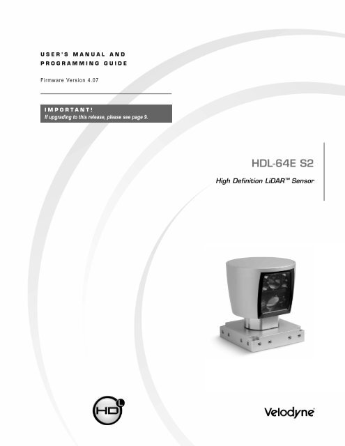
HDL-64E S2 manual_Rev C_2011 - Velodyne Lidar
HDL-64E S2 manual_Rev C_2011 - Velodyne Lidar
HDL-64E S2 manual_Rev C_2011 - Velodyne Lidar
- No tags were found...
Create successful ePaper yourself
Turn your PDF publications into a flip-book with our unique Google optimized e-Paper software.
InstaLLatIon oVerVIeW<strong>HDL</strong>-<strong>64E</strong> <strong>S2</strong> User’s ManualSide MountingMountingBase[152.4mm]6.00[21mm].83[25.4mm]1.00[203.2mm]8.00Figure 3. Side/side <strong>HDL</strong> mounting illustration.[ 4 ]
InstaLLatIon oVerVIeW<strong>HDL</strong>-<strong>64E</strong> <strong>S2</strong> User’s ManualTop MountingFour .406” [10.3mm] throughholes for top mount option tosecure the <strong>HDL</strong> to the vehicle.[33.8mm]1.33[177.8mm]7.00[177.8mm]7.00[12.7mm].50 [12.7mm].50Figure 4. <strong>HDL</strong> top mounting illustration.Figure 4 shows the location of four .406” [10.3mm] thru holes for top mounting.For all mounting options, be sure the <strong>HDL</strong>- <strong>64E</strong> is mounted securely to withstand vibration and shock without risk of detachment. Althoughhelpful for longer life, the unit need not be shock proofed — it is designed to withstand standard automotive G-forces.The <strong>HDL</strong>- <strong>64E</strong> is also weatherproofed to withstand wind, rain, and other adverse weather conditions. The spinning nature of the <strong>HDL</strong>- <strong>64E</strong>helps the unit shed excess water from the front window that could hamper performance.[ 5 ]
InstaLLatIon oVerVIeW<strong>HDL</strong>-<strong>64E</strong> <strong>S2</strong> User’s ManualWiringThe <strong>HDL</strong>- <strong>64E</strong> comes with a pre-wired connector, wired with power, DB9 serial, and standard RJ 45 Ethernet connectors. The connector wiresare approximately 10’ [3 meters] in length.Power. Connect the red and black wires to vehicle power. Be sure red is positive polarity. THE <strong>HDL</strong>- <strong>64E</strong> IS RATED ONLY FOR 12 - 16VOLTS. Any voltage applied over 16 volts could damage the unit. Expect the unit to draw 4- 6 amps during normal usage.note: The <strong>HDL</strong>- <strong>64E</strong> does not have a power switch. It spins whenever power is applied. The <strong>HDL</strong>-<strong>64E</strong> has a lockout circuit that prevents itslasers from firing until it achieves approximately 300 RPMs.Ethernet. This standard Ethernet connector is designed to connect to a standard PC.note: The <strong>HDL</strong>-<strong>64E</strong> is only compatible with network cards that have either MDI or AUTO MDIX capability.Serial Interface. The connector also features an RS- 232 DB9 serial connector. This connector allows for a firmware update to be applied tothe <strong>HDL</strong>- <strong>64E</strong> (<strong>Velodyne</strong> may release firmware updates from time to time). It also accepts commands to change the RPM of the unit, controlHFOV, change the unit’s IP address, and other functions described on page 8.Cable Diagram. If you wish to wire your own connector, refer to Appendix B for a layout of the wiring pins.usaGeThe <strong>HDL</strong>- <strong>64E</strong> sensor needs no configuration, calibration, or other setup to begin producing usable data. Once the unit is mounted and wired,supplying it power will cause it to start scanning and producing data packets. The quickest way to watch the <strong>HDL</strong>-<strong>64E</strong> in action is to useDigital Sensor Recorder (DSR), the viewer included with the unit. DSR reads in the packets from the <strong>HDL</strong>-<strong>64E</strong> over Ethernet, performs thenecessary calculations to determine point locations, then plots the points in 3D on the viewer’s PC. If you have never used the <strong>HDL</strong>-<strong>64E</strong>before, this is the recommended starting point. For more on installing and using DSR, see Appendix C. You can to observe both distanceand intensity data through DSR.Most users, however, will need to create their own application-specific point cloud tracking and plotting and/or storage scheme. There areseveral fundamental steps to this process:1. Establish communication with the <strong>HDL</strong>- <strong>64E</strong>.2. Create a calibration table either from the calibration data included in-stream from the <strong>HDL</strong>- <strong>64E</strong> or from theincluded db.xml data file3. Parse the packets for rotation, block, distance and intensity data4. Apply the calibration factors to the data5. Plot or store the data as neededEach of these steps is described in detail, below.1. Establish communication with the <strong>HDL</strong>- <strong>64E</strong>. The <strong>HDL</strong>- <strong>64E</strong> outputs broadcast UDP packets. By using a network monitoring tool such asWireshark you can capture and observe the packets as they are generated by the unit. The default source IP address for the <strong>HDL</strong>-<strong>64E</strong> is192.168.3.043, and the destination IP address is 192.168.3.255. To change these IP addresses, see page 10.2. Create an internal calibration table either from the calibration data included in-stream from the <strong>HDL</strong>- <strong>64E</strong> or from the includeddb.xml data file. This table must be built and stored internal to the point-cloud processing software. The easiest and most reliable way tobuild the calibration table is by reading the calibration data directly from the UDP data packets. A Matlab example of reading and buildingsuch a table can be found in Appendix D, and on the CD included with the <strong>HDL</strong>-<strong>64E</strong> named: CALTABLEBUILD.m.[ 6 ]
usaGe<strong>HDL</strong>-<strong>64E</strong> <strong>S2</strong> User’s ManualDefine Sensor Memory IP Source and Destination AddressesThe <strong>HDL</strong>- <strong>64E</strong> comes with the following default IP addresses:• Source: 192.168.3.043• Destination: 192.168.3.255To change either of the above IP addresses, issue a serial command of the case sensitive format #<strong>HDL</strong>IPAssssssssssssdddddddddddd$where,• ssssssssssss is the source 12-digit IP address• dddddddddddd is the destination 12-digit IP addressnote: Use all 12 digits to set an IP address. Use 0 (zeros) where a digit would be absent. For example, 192168003043 is the correct syntaxfor IP address 192.168.3.43.note: The unit must be power cycled to adopt the new IP addresses.Upload Calibration DataOlder version <strong>HDL</strong>- <strong>64E</strong> sensors used the db.xml file exclusively for calibration data. The calibration data found in db.xml can be uploadedand saved to the unit’s flash memory by following the steps outlined below.1. Locate the files <strong>HDL</strong>CAL.bat, loadcal.exe, and db.xml from the CD and put them all in the same directory.2. Edit <strong>HDL</strong>CAL.bat to ensure the copy command lists the right COM port for RS-232 communication with the <strong>HDL</strong>- <strong>64E</strong>.3. Run <strong>HDL</strong>CAL.bat and ensure successful completion.4. The <strong>HDL</strong>-<strong>64E</strong> unit now has received and saved the calibration data.To verify successful load of the calibration data, ensure the date and time of the upload have been updated. Refer to Appendix E for where inthe data packets this data can be located.External GPS Time SynchronizationThe <strong>HDL</strong>- <strong>64E</strong> can synchronize its data with precision GPS-supplied time pulses to enable users to ascertain the exact firing time of each laserin any particular packet. The firing time of the first laser in a particular packet is reported in the form of microseconds since the top of the hour,and from that time each subsequent laser’s firing time can be derived via the table published in Appendix H.This capability requires a GPS receiver generating a sync pulse and the $GPRMC NMEA record over a dedicated RS-232 serial port. Theoutput from the GPS receiver is connected to an external GPS adaptor box supplied by <strong>Velodyne</strong> that conditions the signal and passes it tothe <strong>HDL</strong>- <strong>64E</strong>. The GPS receiver can either be supplied by <strong>Velodyne</strong> or the customer can adapt their GPS receiver to provide the requiredsync pulse and NMEA record.GPS Receiver Option 1: Optional <strong>Velodyne</strong> Supplied GPS ReceiverUnder this option, a GPS receiver that is pre-programmed by <strong>Velodyne</strong> Model <strong>HDL</strong>-64-GPS, will be provided to <strong>HDL</strong>- <strong>64E</strong> users. Thisreceiver will be pre-wired with an RS- 232 connector that plugs into the GPS adapter box. To obtain a pre-programmed GPS receiver,contact <strong>Velodyne</strong> sales or service.GPS Receiver Option 2: Customer’s GPS ReceiverUnder this option the customer must configure their GPS device to issue a once-a-second synchronization pulse, typically output over adedicated wire, and configure an available RS-232 serial port to issue a once-a-second $GPRMC NMEA record. No other output can beaccepted from the GPS device. Further, the sync pulse and NMEA record must be issued sequentially. The sync pulse length is notcritical (typical lengths are between 20ms and 200ms), but the $GPRMC record must start between 50ms and 500ms after the end ofthe sync pulse.[ 11 ]
usaGe<strong>HDL</strong>-<strong>64E</strong> <strong>S2</strong> User’s Manualnote: The $GPRMC record can be configured for either hhmmss format or hhmmss.s format.The images below show the GPS adaptor box, included with the <strong>HDL</strong>-<strong>64E</strong>, and optional GPS receiver.GPS EQUIPMENTGPS Adaptor BoxModel No.<strong>HDL</strong>-64-ADAPT(Included)GPS ReceiverModel No.<strong>HDL</strong>-64-GPS(Optional)1 2 3 4 5 6 7 8GPS Adaptor Box Front & Back ViewDB-9 FConnect to HostComputer Serial PortDB-9 MConnect to InterfaceCable from<strong>HDL</strong>-<strong>64E</strong> Unit# COLOR SIGNAL NAME1 Red +12V DC Power2 Black Power Ground3 Yellow 1 PPS (positive edge only)4 Red Vin (+5V)5 Black Ground6 White Transmit Data7 Brown Ground (Drain Wire)8 Green Receive Data[ 12 ]
usaGe<strong>HDL</strong>-<strong>64E</strong> <strong>S2</strong> User’s ManualPacket format and status byte for GPS time stampingThe 6 extra bytes at the end of the <strong>HDL</strong>- <strong>64E</strong> data packet are used to report GPS timing and synchronization data. For every packet, the last6 bytes are formatted as follows:4 bytes: 32 bit unsigned integer time stamp. This value represents microseconds from the top of the hour to the first laser firingin the packet.1 byte: 8 bit ASCII status character as described in Appendix E.1 byte: 8 bit data as described in Appendix E.Within the GPS status byte, there are 4 GPS status indicators:0: no GPS connection.A: both PPS and GPS command have signal.V: only GPS command signal, no PPS.P: only PPS signal, no GPS time command.Time Stamping Accuracy RulesThe following rules and subsequent accuracy apply for GPS time stamping:1. If the GPS isn’t connected (GPS Status 0), the <strong>HDL</strong>- <strong>64E</strong> starts running on its own clock starting at midnight Jan 1 2000. Expecta drift of about 5 seconds per day under this method. This date and time data is reflected in the H, M, S, D, N, and Y data values.Also note that the <strong>HDL</strong>- <strong>64E</strong> clock does not correct for leap years.2. When the GPS is connected, the H, M, S, D, N, and Y data values are obtained from the $GPRMC NMEA record. GPS timesynching runs in one of two modes:a. The GPS has an internal clock that runs for several weeks that will be used first. The accuracy is as good as theGPS device employed.b. When the GPS achieves lock, the <strong>HDL</strong> -<strong>64E</strong> clock will then be within +/-50µs of the correct time at all times.3. If the GPS is then disconnected, the <strong>HDL</strong>- <strong>64E</strong> will continue to run on its own clock and be subject to a drift of approximately5 seconds per day.Laser Firing Sequence and TimingIf the GPS timestamp feature is employed, it may be useful to determine the exact firing time for each laser so as to properly time-align the<strong>HDL</strong>- <strong>64E</strong> point cloud with other data sources.The upper block and lower block collect distance points simultaneously, with each block issuing one laser pulse at a time. That is, eachupper block laser fires in sequence and in unison with a laser from the lower block.Lasers are numbered sequentially starting with 0 for the first lower block laser to 31 for the last lower block laser; and 32 for the first upperblock laser to 63 for the last upper block laser. For example, laser 32 fires simultaneously with laser 0, laser 33 fires with laser 1, and so on.The <strong>HDL</strong>- <strong>64E</strong> has an equal number of upper and lower block returns. Hence, when interpreting the delay table, each sequential pair ofdata blocks represents the upper and lower block respectively. Each upper and lower block data pair in the Ethernet packet has the samedelay value.The first firing of a laser pair occurs 419.3 µs after the issuance of the fire command. Six firings of each block takes 139 µs and then thecollected data is transmitted. It takes 100 µs to transmit the entire 1248 byte Ethernet packet. This is equal to 12.48 Bytes/µs and0.080128 µs/Byte.[ 13 ]
usaGe<strong>HDL</strong>-<strong>64E</strong> <strong>S2</strong> User’s ManualA timing table, shown in Appendix H, shows how much time elapses between the actual capturing of a distance point and when that point isoutput from the device. By registering the event of the Ethernet data capture, you can calculate back in time the exact time at which anyparticular distance point was captured.fIrMWare uPdateFrom time to time <strong>Velodyne</strong> may issue firmware updates. To update the <strong>HDL</strong>- <strong>64E</strong>’s firmware follow the steps below.1. Obtain the update file from <strong>Velodyne</strong>.2. Connect the wiring harness RS-232 cable to a standard Windows compatible PC or laptop serial port.3. Power up the <strong>HDL</strong> unit.4. Execute the update file; the screen below appears.5. Select the appropriate COM port and Click Update.Figure 5. <strong>HDL</strong> software update screen capture.6. The firmware is uploaded and check summed before it is applied to the flash memory inside the <strong>HDL</strong>- <strong>64E</strong>. If the checksum iscorrupted, no update occurs. This protects the <strong>HDL</strong> unit in the event of power or data loss during the update.• If the update is successful, the unit begins to spin down for a few seconds and then powers back up with thenew firmware running.• If the update is not successful, try the update several times before seeking assistance from <strong>Velodyne</strong>.[ 14 ]
aPPendIx a: HdL-64e MecHanIcaL draWInGs<strong>HDL</strong>-<strong>64E</strong> <strong>S2</strong> User’s Manual<strong>HDL</strong>- <strong>64E</strong> Mechanical Drawings260.210.24203.28.0043.21.7021.838.00203.2223.58.80 10.3FOUR .41 THRUFOR TOP MOUNT OPTION177.87.00177.87.00C L C LTWO M8-1.25X12mm DEEPMOUNTING POINTS(2 PER SIDE, FOR ATOTAL OF 8)4.50114.3152.46.0034.31.3517.9.71152.46.00ISOMETRIC VIEW491.9321.83[ 15 ]
aPPendIx B: HdL-64e WIrInG dIaGraM<strong>HDL</strong>-<strong>64E</strong> <strong>S2</strong> User’s Manual<strong>HDL</strong>- <strong>64E</strong> Wiring DiagramHarting Technology GroupMetal Version, Standard Straight StyleModel No. 10-12-005-2001[ 16 ]
aPPendIx c: dIGItaL sensor recorder (dsr)<strong>HDL</strong>-<strong>64E</strong> <strong>S2</strong> User’s Manual<strong>HDL</strong>- <strong>64E</strong> Digital Sensor Recorder (DSR)DSR is a 3 D point cloud visualization software program designed for use with the <strong>HDL</strong>- <strong>64E</strong>. This software is an “out of the box” tool for therendering and recording of point cloud data from the <strong>HDL</strong> unit.You can develop visualization software using the DSR as a reference platform. A code snippet is provided on the CD to aid in understandingthe methods at which DSR parses the data points generated by the <strong>HDL</strong> sensor.InstallTo install the DSR on your computer:1. Locate the DSR executable program on the provided CD.2. Double click on this DSR executable file to begin the installation onto the host computer. We recommend that you use of thedefault settings during the installation.3. Copy the db.XML file supplied with the <strong>HDL</strong>- <strong>64E</strong> into the same directory as the DSR executable (defaults to c:\program files\ DigitalSensor Recorder). You may want to rename the existing default db.XML that comes with the DSR install.note: Failure to use the calibration db.xml file supplied with your sensor will result in an inaccurate point cloud rendering in DSR.CalibrateThe db.xml file provided with the <strong>HDL</strong> unit contains correction factors for the proper alignment of the point cloud information gathered foreach laser. When implemented properly, the image viewable from the DSR is calibrated to provide an accurate visual representation of theenvironment in which the sensor is being used. Also use these calibration factors and equations in any program using the data generatedby the unit.Live Playback:For live playback, first secure and power up the <strong>HDL</strong>-<strong>64E</strong> sensor so that it is spinning. Connect the RJ45 Ethernet connector to your hostcomputer’s network connection. You may wish to utilize auto DNS settings for your computers network configuration.DSR desktop icon =Open DSR from your desktop icon created during the installation. Pull down the “Options” menu and select the proper input device.Go to “Options” again and deselect the “Show Ground Plane” option. (Leave this feature off for the time being or until the groundplane has been properly adjusted).You can now go to “Options/Properties” to change the individual settings for each LASER channel if so desired.REFRESH button =Provided that your computer is now receiving data packets, click on the Refresh button to start live viewing of a point cloud. The initial imageis of a directly overhead perspective. See page 17 for mouse and key commands used to manipulate the 3D image within the viewer.note: The image can be manipulated in all directions and become disorienting. If you lose perspective, simply press F1 to return to theoriginal view.Recording Data:RECORD button =[ 17 ]
aPPendIx c<strong>HDL</strong>-<strong>64E</strong> <strong>S2</strong> User’s ManualOnce the input of streaming data has been confirmed through the live playback feature, click on the Record button and the program willrequest the name and location for the pcap file to be created. Recording will begin immediately once the file information has been entered.Click on the Record button again to discontinue the capture. One can string multiple recordings together on the same file by performing theRecord function repeatedly. A new file name will not be requested until after the session has been aborted.note: An Ethernet capture utility such as Wireshark can also be used as a pcap capture utility.Playback of Recorded files:Use the File › Open command to open a previously captured pcap file for playback. The DSR playback controls are similar to anyDVD/VCR control features.PLAY button = PAUSE button =Press the Play button to render the file. The Play button will alternate to Pause when in playback mode.FORWARD button = REVERSE button =Use the Forward and <strong>Rev</strong>erse buttons to change the direction of playback.note: The X, Y, Z and distance figures at the bottom of the image represent the distance of the x, y, z crosshairs with respect to the originpoint indicated by the small white circle. The concentric gray circles and grid lines represent 10 meter increments from the sensor.Following is an example image of the calibration values as seen in DSR/File/Properties screen. Values will be different than those on your CD.Figure 6. Calibration values as seen in DSR/File/Properties[ 18 ]
aPPendIx c<strong>HDL</strong>-<strong>64E</strong> <strong>S2</strong> User’s ManualDSR Key ControlsZoom:Z = Zoom inShift, Z = Zoom outZ Axis Rotation:Y = Rotate CWShift, Y = Rotate CCWX Axis Rotation:P = Rotate CWShift, P = Rotate CCWY Axis Rotation:R = Rotate CWShift, R = Rotate CCWZ Shift:F = ForwardB = BackX Shift:L = LeftH = RightY Shift:U = UpD = DownAux. Functions:Ctrl, (Z,Y,P,R,F,B,L,H,U,D) Direction = Fine MovementAlt, (Z,Y,P,R,F,B,L,H,U,D) Direction = Very Fine MovementDSR Mouse ControlsRotational:Left Button/MoveSlide:Right Button/MoveZoom:Scroll forward = Zoom InScroll backward = Zoom Out[ 19 ]
aPPendIx d<strong>HDL</strong>-<strong>64E</strong> <strong>S2</strong> User’s Manual% Add high and low bytes of Rotational Correction Factor together and check ifpositive or negative correction factor.RotationalCorr(i)=temp(5)*256+temp(4);if RotationalCorr(i)>32768RotationalCorr(i)=RotationalCorr(i)-65536;End% Scale Rotational Correction Factor by Diving by 100.RotationalCorr(i)=RotationalCorr(i)/100;% Add high and low bytes of remaining 2 Byte Correction Factors together andcheck if positive or negative correction factor, if necessary. Scale dimensionsin mm to cm by Diving by 10. Scale Focal Slope by Dividing by 10.DistanceCorr(i)=(temp(7)*256+temp(6))/10;DistanceCorrX(i)=(temp1(2)*256+temp1(1))/10;DistanceCorrY(i)=(temp1(4)*256+temp1(3))/10;VerticalOffset(i)=(temp1(6)*256+temp1(5))/10;HorizonOffset(i)=(temp2(1)*256+temp1(7));if HorizonOffset(i)>32768HorizonOffset(i)=HorizonOffset(i)-65536;endHorizonOffset(i)=HorizonOffset(i)/10;FocalDist(i)=temp2(3)*256+temp2(2);if FocalDist(i)>32768FocalDist(i)=FocalDist(i)-65536;endFocalDist(i)=FocalDist(i)/10;FocalSlope(i)=temp2(5)*256+temp2(4);if FocalSlope(i)>32768FocalSlope(i)=FocalSlope(i)-65536;endFocalSlope(i)=FocalSlope(i)/10;% Maximum and Minimum Intensity only 1 Byte each.MinIntensity(i)=temp2(6);MaxIntensity(i)=temp2(7);End% Done with correction factors.% Get Unit Parameter Datas=Ind(1)char(status(s-80:s+6))value(s-80:s+6)[ 21 ]
aPPendIx d<strong>HDL</strong>-<strong>64E</strong> <strong>S2</strong> User’s ManualVersion=dec2hex(value(s-1))Temperature=value(s-2)GPS=value(s-3)speed=single(value(s-48))+single(value(s-47))*256Fov_start=single(value(s-46))+single(value(s-45))*256Fov_end=single(value(s-44))+single(value(s-43))*256warning=value(s-13)power=value(s-12)Humidity=value(s-58)% Done with Unit Parameters.Reading Calibration and Sensor Parameter DataLaser ID # is a 1 byte integer. Most of the output calibration data are 2 byte signed integers except minimum and and maximum intensity,which use 1 byte each. Vertical and rotational angle correction integers have to be divided by a scale factor of 100. Other distance relatedcorrection units are in mm. To convert to cm, they need to be divided by a factor of 10. Focal slope also need to be divided by 10.[ 22 ]
aPPendIx e: HdL-64e saMPLe data PacKet<strong>HDL</strong>-<strong>64E</strong> <strong>S2</strong> User’s ManualData Packet FormatThe <strong>HDL</strong>-<strong>64E</strong> outputs UDP Ethernet packets. Each packet contains a header, a data payload of firing data and status data. Data packetsare assembled with the collection of all firing data for six upper block sequences and six lower block sequences. The upper block laserdistance and intensity data is collected first followed by the lower block laser data. The data packet is then combined with status andheader data in a UDP packet transmitted over Ethernet. The data packet is transmitted starting with the last byte acquired in a last in,first out (LIFO) data order.The status data always contains a GPS 4 byte timestamp representing milliseconds from the top of the hour. In addition, the status datacontains one type of data. The other status data rotates through a sequence of different pieces of information. See datagram on thenext page.[ 23 ]
aPPendIx e<strong>HDL</strong>-<strong>64E</strong> <strong>S2</strong> User’s ManualFirmware version 4.07 (sheet 1 of 3)47Version 4.07[ 24 ]
aPPendIx e<strong>HDL</strong>-<strong>64E</strong> <strong>S2</strong> User’s ManualFirmware version 4.07 (sheet 2 of 3)Reserved*Reserved*Reserved*Reserved*Reserved*Reserved*Upper Block ThresholdLower Block ThresholdFEFF*For Laser 63, these bytes will contain the time stamp representing when the calibration data was uploaded in the following sequence:* Year* Month* Day* Hour* Min* Sec.[ 25 ]
aPPendIx e<strong>HDL</strong>-<strong>64E</strong> <strong>S2</strong> User’s ManualFirmware version 4.07 (sheet 3 of 3)ThresholdBoth = 2Strongest = 0Last = 1A8[ 26 ]
aPPendIx e<strong>HDL</strong>-<strong>64E</strong> <strong>S2</strong> User’s ManualLast Six Bytes ExamplesExamples of the last row of 11 consecutive packets follows. In all cases, the “seconds” figure represents the origin of the packetexpressed in seconds since the top of the hour.PACKET #7648:PACKET #7649:PACKET #7650:PACKET #7651:[ 27 ]
aPPendIx e<strong>HDL</strong>-<strong>64E</strong> <strong>S2</strong> User’s ManualPACKET #7652:PACKET #7653:PACKET #7654:PACKET #7655:PACKET #7656:4740 = Ver 4.07[ 28 ]
aPPendIx e<strong>HDL</strong>-<strong>64E</strong> <strong>S2</strong> User’s ManualPACKET #7657:Not used(Spare)PACKET #7658:Not used(Spare)[ 29 ]
aPPendIx f: duaL tWo PoInt caLIBratIon MetHodoLoGy<strong>HDL</strong>-<strong>64E</strong> <strong>S2</strong> User’s ManualDual Two Point Calibration Methodology and Code Samples<strong>Velodyne</strong> uses a dual point calibration methodology to calculate the values in the db.xml file. This section describes this calibrationmethodology. The steps for the calibration are as follows:1: Perform far point calibration at 25.04m.2: Perform near point X calibration at 2.4m3: Perform near point Y calibration at 1.93m4: Perform linear interpolation to get distance correction for X and Y (Nearer than 25.00/m only)The formula for the calibration value is as follows:D y = D 1y + (D 2 - D 1y )D x = D 1x + (D 2 - D 1x )Where:x 1 = 2.4 mx 2 = 25.04 mD 1x = corrected X distance for near pointD 1y = corrected Y distance for near pointD 2x = corrected X distance for far pointD 2y = corrected X distance for far point(x - 0) _______(x 2 - 0)(x - x 1 ) _______(x 2 - x 1 )Coordinate Calculation Algorithm Sample CodefiringData::computeCoords(guint16 laserNum, boost::shared_ptr db,GLpos_t &pos){guint16 idx = laserNum % VLS_LASER_PER_FIRING;boost::shared_ptr cal = db->getCalibration(laserNum);if (data->points[idx].distance == 0) {coords[idx].setX(0.0);coords[idx].setY(0.0);coords[idx].setZ(0.0);return;}// Get measured distance, distance1float distance1 = db->getDistLSB() * (float)data->points[idx].distance;// Corrected distance by distance calibration at 25.04mfloat distance = distance1+ cal->getDistCorrection();float cosVertAngle = cal->getCosVertCorrection();float sinVertAngle = cal->getSinVertCorrection();[ 30 ]
aPPendIx f<strong>HDL</strong>-<strong>64E</strong> <strong>S2</strong> User’s Manualfloat cosRotCorrection = cal->getCosRotCorrection();float sinRotCorrection = cal->getSinRotCorrection();float cosRotAngle = rotCosTable[data->position]*cosRotCorrection +rotSinTable[data->position]*sinRotCorrection;float sinRotAngle = rotSinTable[data->position]*cosRotCorrection -rotCosTable[data->position]*sinRotCorrection;float hOffsetCorr = cal->getHorizOffsetCorrection()/VLS_DIM_SCALE;float vOffsetCorr = cal->getVertOffsetCorrection()/VLS_DIM_SCALE;; //Convert distance to X-Y plane, formular is: xyDistance = distance * cosVertAnglefloat xyDistance = distance * cosVertAngle// Calculate temporal X, use absolute value.float xx = xyDistance * sinRotAngle - hOffsetCorr * cosRotAngle + pos.getX();// Calculate temporal Y, use absolute valuefloat yy = xyDistance * cosRotAngle + hOffsetCorr * sinRotAngle + pos.getY();if (xxgetDistCorrectionX())*(xx-240)/(2504-240)+cal->getDistCorrectionX();float distanceCorrY = (cal->getDistCorrection()-cal->getDistCorrectionY())*(yy-193)/(2504-193)+cal->getDistCorrectionY(); //fix in V2.0// Unit convert: cm converts to meterdistance1 /= VLS_DIM_SCALE;distanceCorrX /= VLS_DIM_SCALE;distanceCorrY /= VLS_DIM_SCALE;// Measured distance add distance correction in X.distance = distance1+distanceCorrX;xyDistance = distance * cosVertAngle; // Convert to X-Y plane// Calculate X coordinatecoords[idx].setX(xyDistance * sinRotAngle - hOffsetCorr * cosRotAngle +pos.getX()/VLS_DIM_SCALE);// Measured distance add distance correction in Y.distance = distance1+distanceCorrY;xyDistance = distance * cosVertAngle; //Convert to X-Y plane// Calculate Y coordinatecoords[idx].setY(xyDistance * cosRotAngle + hOffsetCorr * sinRotAngle +pos.getY()/VLS_DIM_SCALE);//Calculate Z coordinate, formula is : setZ(distance * sinVertAngle +vOffsetCorrcoords[idx].setZ(distance * sinVertAngle + vOffsetCorr +pos.getZ()/VLS_DIM_SCALE);}[ 31 ]
aPPendIx f<strong>HDL</strong>-<strong>64E</strong> <strong>S2</strong> User’s ManualIntensity Compensation vs DistanceIntensity compensation is done in the software for different channels by changing a parameter in the calibration window until the measurementgets to a uniform intensity for a reference target.focalOffset = 256 ( ______________1 - focalDistance ) 213100intensityVal = intensityVal + K [ focalOffset - 256 ( __________ 1 - distance ) 2]65535Here K is the slope from the calibration data. Intensity gets to its maximum at the focal distance for different channels and fromits calibration data.Calibration WindowThe following new intensity parameters have been added in the db.xml calibration file• focal distance: At this distance, the intensity goes to max. The focal distance is different from laser to laser. On the upper block,it averages 1500cm. On the lower block, it averages 800cm.• focal slope: This parameter controls intensity compensation. Min and Max Intensity are used to scale and offset intensity.Intensity Value Corrected by Distance Codefor (guint i=0; i< VLS_LASER_PER_FIRING; i++) {guit laser = i + base;if (!db->getEnabled(laser))continue;bool intensity =db->getIntensity(laser);if (!intensity: {glColor3fv(db->getDisplayColor(laser).rgb);} else {guchar minIntensity = 0, maxIntensity = 0;float intensityScale = 0;minIntensity = db->getMinIntensity(laser);maxIntensity = db->getMaxIntensity(laser);//Get intensity scaleintensityScale = (float)(maxIntensity - minIntensity);// Get firing “i” intensityguchar intensityVal = it->getPoint(i)->intensity;// Get firing “i” distance, here unit is 2mmfloat distance = it->getPoint(i)->distance;// Calculate offset according calibrationfloat focaloffset= 256*(1-db->getFocalDistance(laser)/13100)*(1-db->getFocalDistance(laser)/13100);// get slope from calibrationfloat focalslope = db->getFocalSlope(laser);[ 32 ]
aPPendIx f<strong>HDL</strong>-<strong>64E</strong> <strong>S2</strong> User’s Manual// Calculate corrected intensity vs distancefloat intensityVal1 = intensityVal + focalslope*(abs(focaloffset-256*(1-distance/65535)*(1-distance/65535)));if (intensityVal1 < minIntensity) intensityVal1=minIntensity;if (intensityVal1 > maxIntensity) intensityVal1=maxIntensity;// Scale to new intensity scalefloat intensityColor = (float)(intensityVal1 - minIntensity) / intensityScale;// Convert to jet colorint rgb=(int)(intensityColor*63);glColor3f(rcolor[rgb], gcolor[rgb], bcolor[rgb]);}G1Vertex3fv(it->getCoord(i).xyz;}it->operator++();[ 33 ]
aPPendIx G<strong>HDL</strong>-<strong>64E</strong> <strong>S2</strong> User’s Manual<strong>HDL</strong>-<strong>64E</strong> Ethernet Timing Table OverviewThe <strong>HDL</strong>-<strong>64E</strong> Ethernet Timing Table shows how much time elapses between the actual capturing of a point’s data event and when that pointis an event output from the <strong>HDL</strong>-<strong>64E</strong>. By registering the event of the Ethernet data capture, you can calculate back in time the exact time atwhich any particular distance point was captured. The formula is as follows:Actual Event Timestamp = (Data Packet Event Output Timestamp) – (Timing Table Event Timestamp)In the <strong>HDL</strong>-<strong>64E</strong>, the upper block and lower block collect distance points simultaneously with each block issuing single laser pulses at a time.That is, each upper block laser fires in sequence and in unison to a corresponding laser from the lower block. For example, laser 32 firessimultaneously with laser 0, laser 33 fires with laser 1, and so on. The <strong>HDL</strong>-<strong>64E</strong> has an equal number of upper and lower block returns.This is why when interpreting the delay table each sequential pair of data blocks will represent the upper and lower block respectively,and each upper and lower block pair of data blocks in the Ethernet packet will have the same delay values.Ethernet packets are assembled until the entire 1200 bytes have been collected, representing six upper block sequences and six lower blocksequences. The packet is then transmitted via a UDP packet over Ethernet, starting from the last byte acquired. See a sample of the packetlayout in Appendix E.[ 34 ]
aPPendIx G<strong>HDL</strong>-<strong>64E</strong> <strong>S2</strong> User’s Manual<strong>HDL</strong>-<strong>64E</strong> Ethernet Transmit Timing TableHow to use this tableThe table represents an <strong>HDL</strong>-<strong>64E</strong> data packet. The laser returns will come outin the order listed. Simply subtract from the timestamp of the output event of thepacket each data value to arrive at the actual time the distance point wascaptured inside the <strong>HDL</strong>-<strong>64E</strong>.Data LaserLaser Numbers Lower, UpperBlock Block 0,32 1,33 2,34 3,35 4,36 5,37 6,38 7,39 8,40 9,41 10,42 11,43 12,44 13,45 14,46 15,47 16,481 Upper 419.3 418.6 417.8 417.1 416.4 415.7 414.9 414.2 413.5 412.7 412.0 411.3 410.6 409.8 409.1 408.4 407.72 Lower 419.3 418.6 417.8 417.1 416.4 415.7 414.9 414.2 413.5 412.7 412.0 411.3 410.6 409.8 409.1 408.4 407.73 Upper 396.0 395.3 394.5 393.8 393.1 392.4 391.6 390.9 390.2 389.5 388.7 388.0 387.3 386.5 385.8 385.1 384.44 Lower 396.0 395.3 394.5 393.8 393.1 392.4 391.6 390.9 390.2 389.5 388.7 388.0 387.3 386.5 385.8 385.1 384.45 Upper 372.7 372.0 371.3 370.5 369.8 369.1 368.3 367.6 366.9 366.2 365.4 364.7 364.0 363.2 362.5 361.8 361.16 Lower 372.7 372.0 371.3 370.5 369.8 369.1 368.3 367.6 366.9 366.2 365.4 364.7 364.0 363.2 362.5 361.8 361.17 Upper 349.4 348.7 348.0 347.2 346.5 345.8 345.0 344.3 343.6 342.9 342.1 341.4 340.7 339.9 339.2 338.5 337.88 Lower 349.4 348.7 348.0 347.2 346.5 345.8 345.0 344.3 343.6 342.9 342.1 341.4 340.7 339.9 339.2 338.5 337.89 Upper 326.1 325.4 324.7 323.9 323.2 322.5 321.7 321.0 320.3 319.6 318.8 318.1 317.4 316.7 315.9 315.2 314.510 Lower 326.1 325.4 324.7 323.9 323.2 322.5 321.7 321.0 320.3 319.6 318.8 318.1 317.4 316.7 315.9 315.2 314.511 Upper 302.8 302.1 301.4 300.6 299.9 299.2 298.5 297.7 297.0 296.3 295.5 294.8 294.1 293.4 292.6 291.9 291.212 Lower 302.8 302.1 301.4 300.6 299.9 299.2 298.5 297.7 297.0 296.3 295.5 294.8 294.1 293.4 292.6 291.9 291.2[ 35 ]
aPPendIx H: Laser and detector arranGeMent<strong>HDL</strong>-<strong>64E</strong> <strong>S2</strong> User’s ManualUse this chart to troubleshoot common problems with the <strong>HDL</strong>-<strong>64E</strong>.LASER AS SEENFROM THE BACK OF THE UNITLASER BEAM ON THE WALLAS SEEN ON CAMERA INNIGHT VISION MODE[ 36 ]
aPPendIx I: anGuLar resoLutIon<strong>HDL</strong>-<strong>64E</strong> <strong>S2</strong> User’s ManualUpper & Lower BlockRPM RPS Points Points Per <strong>Rev</strong>olution Angular Resolution(Hz) <strong>Rev</strong>olution Per Laser (degrees)300 5 266624 4166 0.0864600 10 133312 2083 0.1728900 15 88896 1389 0.2591note: 20,833 points per second, per laser x 64 = 1,333,312 total points per second therefore, the <strong>HDL</strong>-<strong>64E</strong> generates greater than1.3 million points per second.[ 37 ]
trouBLesHootInG<strong>HDL</strong>-<strong>64E</strong> <strong>S2</strong> User’s ManualUse this chart to troubleshoot common problems with the <strong>HDL</strong>-<strong>64E</strong>.ProblemResolutionUnit doesn’t spinVerify power connection and polarity.Verify proper voltage – should be 16 voltsdrawing about 3-4 amps.Remove bottom cover and check inline 10 amp fuse.Replace if necessary. Model No. ATM-10.Unit spins but no dataVerify Ethernet wiring.Verify packet output with another tool(e.g. Ethereal/Wireshark).No serial communicationVerify RS-232 cable connection.Unit must be active and spinning forRS-232 update.It may take several tries for the updateto be effective.serVIce and MaIntenanceThere are no user service or maintenance requirements or procedures for the <strong>Velodyne</strong> <strong>HDL</strong>-<strong>64E</strong>.For service or maintenance, please contact <strong>Velodyne</strong> at (408) 465-2800, or log on to our website at www.velodynelidar.com.[ 38 ]
sPecIfIcatIons<strong>HDL</strong>-<strong>64E</strong> <strong>S2</strong> User’s ManualSensor:Laser:Mechanical:Output:Dimensions(H/W/D):Shipping Weight:(approx.)• 64 lasers/detectors• 360 degree field of view (azimuth)• 0.09 degree angular resolution (azimuth)• Vertical Field of View:<strong>S2</strong>: +2 — -8.33 @ 1/3 degree spacing-8.83 — -24.33 @ 1/2 degree spacing<strong>S2</strong>.1: +2 — -29.5 @ 1/2 degree spacing•
<strong>Velodyne</strong> LiDAR, Inc.345 Digital DriveMorgan Hill, CA 95037408.465.2800 voice408.779.9227 fax408.779.9208 service faxwww.velodynelidar.comService E mail: lidarservice@velodyne.comProduct E mail: help@velodyne.comTechnical E mail: lidarhelp@velodyne.comSales E mail: lidar@velodyne.comAll <strong>Velodyne</strong> products are made in the U.S.A.Specifications subject to change without noticeOther trademarks or registered trademarks are property of their respective owner.63 <strong>HDL</strong><strong>64E</strong> <strong>S2</strong> <strong>Rev</strong> C FEB11


