Instructions - Hot-Spark Performance Products - Electronic Ignition ...
Instructions - Hot-Spark Performance Products - Electronic Ignition ...
Instructions - Hot-Spark Performance Products - Electronic Ignition ...

Create successful ePaper yourself
Turn your PDF publications into a flip-book with our unique Google optimized e-Paper software.
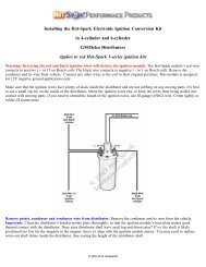
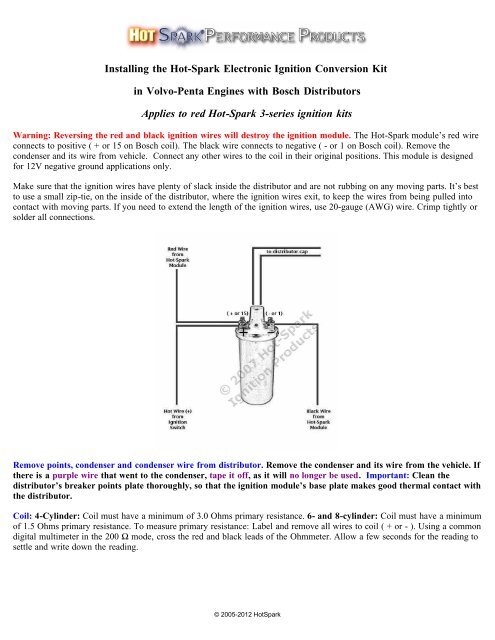
Installing the <strong>Hot</strong>-<strong>Spark</strong> <strong>Electronic</strong> <strong>Ignition</strong> Conversion Kit<br />
in Volvo-Penta Engines with Bosch Distributors<br />
Applies to red <strong>Hot</strong>-<strong>Spark</strong> 3-series ignition kits<br />
Warning: Reversing the red and black ignition wires will destroy the ignition module. The <strong>Hot</strong>-<strong>Spark</strong> module’s red wire<br />
connects to positive ( + or 15 on Bosch coil). The black wire connects to negative ( - or 1 on Bosch coil). Remove the<br />
condenser and its wire from vehicle. Connect any other wires to the coil in their original positions. This module is designed<br />
for 12V negative ground applications only.<br />
Make sure that the ignition wires have plenty of slack inside the distributor and are not rubbing on any moving parts. It’s best<br />
to use a small zip-tie, on the inside of the distributor, where the ignition wires exit, to keep the wires from being pulled into<br />
contact with moving parts. If you need to extend the length of the ignition wires, use 20-gauge (AWG) wire. Crimp tightly or<br />
solder all connections.<br />
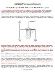
Remove points, condenser and condenser wire from distributor. Remove the condenser and its wire from the vehicle. If<br />
there is a purple wire that went to the condenser, tape it off, as it will no longer be used. Important: Clean the<br />
distributor’s breaker points plate thoroughly, so that the ignition module’s base plate makes good thermal contact with<br />
the distributor.<br />
Coil: 4-Cylinder: Coil must have a minimum of 3.0 Ohms primary resistance. 6- and 8-cylinder: Coil must have a minimum<br />
of 1.5 Ohms primary resistance. To measure primary resistance: Label and remove all wires to coil ( + or - ). Using a common<br />
digital multimeter in the 200 Ω mode, cross the red and black leads of the Ohmmeter. Allow a few seconds for the reading to<br />
settle and write down the reading.<br />
© 2005-2012 <strong>Hot</strong><strong>Spark</strong>
Still in the 200 Ohm mode, measure between coil’s + and - terminals. Allow a few seconds for the reading to settle, until it<br />
stabilizes. Subtract the previous reading, taken with the leads crossed, to compensate for multimeter’s inherent resistance. Do<br />
not use a low-resistance coil, such as the MSD or Accel coil; they don’t have enough primary resistance for this application.<br />
Using a coil with too little primary resistance can cause the ignition module to overheat and misfire until it cools down<br />
again or fail, voiding the warranty.<br />
Check the voltage reading at the coil's + terminal, engine running, at 2,500+ RPM. If the voltage measures more than +14<br />
volts, you'll need to replace the voltage regulator, install a coil with 3.0 Ohms or more internal primary resistance or install a<br />
1.4 Ohm external ballast resistor between the ignition switch and the coil's + terminal.<br />
For best performance, the coil should also have a 7,000 Ohms or more secondary resistance (measured from coil’s + or –<br />
terminal to center high tension terminal, in the 20K Ω mode of the Ohmmeter).<br />
Test Maximum Charging System Voltage: If the charging system voltage, measured at the coil’s positive terminal, is more<br />
than 14 volts at 2,500+ RPM, the voltage regulator likely needs replacing. Too much voltage can damage the ignition module<br />
and other electronic components.<br />
Test Battery Voltage to Coil: With ignition switch ON, engine not running, check voltage at coil’s + terminal. The voltmeter<br />
should read somewhere around +11 to +13 volts. If voltage is too low or there’s no reading, the battery’s terminals or ground<br />
connection may be corroded and need cleaning or the battery may need charging. Some vehicles have a resistor wire running<br />
from the ignition switch to the coil’s + terminal. If this resistor wire drops the voltage below 9 volts or so, you may need to<br />
run a non-resistor wire from the ignition switch to the coil’s + terminal or run a +12V wire directly from the ignition switch<br />
to the red <strong>Hot</strong>-<strong>Spark</strong> ignition wire. Make sure that the ignition switch terminal to which you connect this wire has power only<br />
when the ignition switch is in the ON position. Or, you can, for temporary testing purposes only, run a wire directly from the<br />
battery's + terminal to the coil's + terminal, the <strong>Hot</strong> <strong>Spark</strong> ignition's red wire to the coil's + terminal and the black <strong>Hot</strong>-<strong>Spark</strong><br />
wire to the coil's - terminal. Do not leave the wire from the battery connected to the coil's + terminal for more than a minute<br />
or so without the engine running.<br />
Air Gap between Magnet Sleeve and <strong>Ignition</strong> Sensor: If you need to increase air gap slightly, hold ignition base plate away<br />
from distributor shaft while tightening set screw and/or loosen the two Allen head screws and retighten screws while lightly<br />
prying ignition module away from magnet sleeve. Do not over-torque these Allen screws. Black magnet sleeve should not rub<br />
against red ignition module, but exact gap is not critical. In rare instances, it may be necessary to gently pry red ignition<br />
module away from black magnet sleeve to keep them from rubbing together.<br />
<strong>Ignition</strong> Timing: Set the ignition timing, with a stroboscopic light, to the distributor’s factory specification. The difference in<br />
distributor position with points vs. electronic ignition can be as much as 30 degrees or so clockwise or counterclockwise, so<br />
you’ll definitely have to reset the timing, using a stroboscopic timing light.<br />
Jump-starting the Vehicle: Use caution when jump-starting the vehicle. Connect the battery's + terminal to the other<br />
vehicle's battery's + terminal. Connect the negative (black) part of the jumper cable to engine ground points, such as a bolt on<br />
the engine block, on both vehicles. Do not turn the ignition switch to the ON position while the vehicle at the other end of the<br />
jumper cables is running. Charge your vehicle's battery with the other vehicle or with a battery charger and then remove the<br />
jumper cables or charger before turning on the ignition switch and starting your vehicle. If the ignition switch is in the ON<br />
position while both vehicles are running, the electrical surge resulting from both vehicles' charging systems being connected<br />
together with jumper cables could be enough to destroy the ignition module and/or other automotive electronic components.<br />
© 2005-2012 <strong>Hot</strong><strong>Spark</strong>
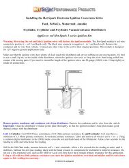
3BOS4U1 for 4-cylinder Bosch Vacuum- or Centrifugal-advance Distributor<br />
1. Turn off the ignition switch and/or remove the ground strap from the battery. Though not absolutely necessary, it is<br />
probably easiest overall to remove the distributor from the car before installing the <strong>Hot</strong>-<strong>Spark</strong> module. If the contacts in the<br />
inside of the distributor cap are worn or damaged, replace the distributor cap. Replace the rotor if it’s worn.<br />
2. Remove distributor cap, leaving the plug wires in place, unless replacing the distributor cap as well.<br />
3. Remove points, condenser and the condenser’s wire from the vehicle. Because the <strong>Hot</strong>-<strong>Spark</strong> kit does not modify the<br />
distributor, the points and condenser can be reinstalled at a later time.<br />
4. Clean any grease or dirt thoroughly from the distributor’s points cam and the breaker points plate.<br />
5. Insert the <strong>Hot</strong>-<strong>Spark</strong> module’s wires, one at a time, from the inside of the distributor out, through the hole in the side of the<br />
distributor. Gently pull and rock, up-and-down and side-to-side, the rubber grommet, halfway through the hole, until it seats.<br />
6. Clean the breaker plate thoroughly to provide a solid electrical ground and good thermal transfer. You can apply a very thin<br />
coat of thermal transfer paste to the bottom of the ignition base plate. Place the <strong>Hot</strong>-<strong>Spark</strong> module’s bottom plate onto the<br />
distributor’s breaker plate. The peg should fit snugly into the hole in the breaker plate and the screw holes should line up. The<br />
<strong>Hot</strong>-<strong>Spark</strong> module’s base plate should lie flat and snug on the distributor’s breaker plate. Insert the screw and tighten, while<br />
gently pressing the ignition module away from the distributor shaft.<br />
3BOS4U1 (supersedes 3BOS4V1 and 3BOS4C1): Universal ignition kit for 4-cylinder Bosch distributors. Fits both<br />
vacuum-advance and centrifugal-advance-only distributors with one-piece, right-hand points. If you need to increase the air<br />
gap slightly, hold the ignition base plate away from the distributor shaft while tightening the points set screw and/or loosen<br />
the two Allen head screws and retighten the screws while lightly prying the ignition module away from magnet sleeve. Do<br />
not over-torque these Allen screws.<br />
3BOS6U1 (supersedes 3BOS6V1): Universal ignition kit for 6-cylinder Bosch distributors with one-piece, right-hand points.<br />
Fits both vacuum-advance and centrifugal-advance-only distributors. Installation is similar to 3BOS4U1.<br />
3BOS6U1L Universal ignition kit for 6-cylinder Bosch distributors with one-piece, left-hand points. Fits both vacuumadvance<br />
and centrifugal-advance-only distributors. Installation is similar to 3BOS4U1.<br />
7. Install magnet sleeve, with the larger opening down. Turn the magnet sleeve left and right, while pushing down firmly,<br />
until you can feel the distributor shaft cam lobes line up with the flat spots inside the magnet sleeve Press down firmly until<br />
the magnet sleeve slides as far down as it will. Install the rotor on top of the magnet sleeve, making sure the rotor is aligned<br />
with the slot in the top of the distributor shaft. The rotor should slide all the way down and lock into place, so that it cannot<br />
turn independently of the distributor shaft. If you can still turn the rotor independently of the distributor shaft, the magnet<br />
sleeve and/or rotor is not seated all the way down.<br />
© 2005-2012 <strong>Hot</strong><strong>Spark</strong>
Magnet sleeve positioned too high: Situation: The fit between the distributor shaft and the magnet sleeve is especially tight<br />
and you can't slide the magnet sleeve down onto the distributor shaft all the way. The rotor rides too high, causing the<br />
distributor cap to wobble when you rotate the distributor shaft. Fix: Rotate the magnet sleeve so that it lines up with the lobes<br />
of the distributor shaft cam and the magnet sleeve can slide down a bit. Install the rotor and tap lightly, with a small hammer<br />
or a soft rubber mallet, on the center of the rotor, until the magnet sleeve seats firmly onto the distributor shaft, over the<br />
distributor cam lobes. With the rotor and distributor cap installed, you should be able to rotate the distributor shaft without the<br />
distributor cap wobbling. If the distributor cap still wobbles, you may need to adjust the number or thickness of the distributor<br />
shaft shims.<br />
Magnet sleeve fit too loose: If the fit between the distributor shaft lobes and the magnet sleeve is too loose, the distributor<br />
shaft may be worn down from years of the points block rubbing on the distributor cam lobes, with accumulated dirt and grit,<br />
and/or insufficient lubrication. If the fit is especially loose, the only solution, short of replacing the distributor, may be to<br />
clean the distributor cam lobes thoroughly with alcohol and wrap the lobes with a single wrap of high-quality electrical tape,<br />
before pressing the magnet sleeve down over the lobes. Too loose a fit between magnet sleeve and distributor cam lobes can<br />
result in erratic timing.<br />
8. Check to see if the vacuum advance is working properly by sucking on the vacuum canister port (vacuum distributors<br />
only). The breaker plate should move smoothly and freely.<br />
9. Adjust the two <strong>Hot</strong>-<strong>Spark</strong> ignition wires so that they have plenty of slack inside the distributor and they’re not rubbing on<br />
any moving parts.<br />
10. Install the distributor cap.<br />
11. Reinstall the distributor.<br />
12. The <strong>Hot</strong>-<strong>Spark</strong> module’s red wire connects to positive ( + or 15 on Bosch coil). The black wire connects to negative ( - or<br />
1 on Bosch coil). DO NOT reverse these wires or the ignition module will be destroyed.<br />
13. Check all wire connections, including the two <strong>Hot</strong>-<strong>Spark</strong> wires and the spark plug and coil high-tension wires. If you need<br />
to extend the length of the wires, use 18- or 20-gauge wire. We recommend soldering all splices and connections, if you can,<br />
or crimp all connections tightly. Make doubly sure that all wires are connected to the proper terminals, etc. before<br />
reconnecting the battery or turning the ignition switch to the ON position. Make sure that all connectors are snug. Reconnect<br />
the battery and set the distributor timing statically. It's a good idea to secure the wires inside the distributor, next to where<br />
they exit, with a zip tie, to keep the wires from being pulled into contact with the spinning magnet sleeve or rotor.<br />
14. You can set the timing statically to about 0° (TDC) at first, so that the engine will start. You may need to tweak the<br />
distributor, a little at a time, right or left, to enable the engine to start and remain running. Time the engine with a<br />
stroboscopic light, engine running, according to Volvo-Penta specifications.<br />
Setting Timing: This will probably be the last time you have to set the timing for a long time, so it’s worth it to spend the<br />
extra time and effort to set the timing absolutely spot-on accurately. An engine with its timing set to perfection will start with<br />
the slightest bump of the starter and purr like a kitten at idle – something to make you feel good every time you start the<br />
engine.<br />
TDC = Top Dead Center, or 0° BTDC = Before Top Dead Center ATDC = After Top Dead Center<br />
Distributor Cap and Rotor: Stock Bosch rotors and distributor caps work fine with the <strong>Hot</strong>-<strong>Spark</strong> module. A worn, corroded<br />
or scored distributor cap and/or rotor is often the cause of the timing jumping around erratically at idle. With the <strong>Hot</strong>-<strong>Spark</strong><br />
electronic ignition installed in place of points, several times as much voltage surges through the rotor to the distributor cap<br />
terminal contacts. While the rotor and distributor cap may have functioned alright with points, the increased strain of double<br />
the voltage may be too much for the old, worn rotor and distributor cap. We recommend installing a new distributor cap and<br />
rotor when converting from points to electronic ignition.<br />
<strong>Spark</strong> Plug Gap: With the <strong>Hot</strong>-<strong>Spark</strong> ignition kit, the stock spark plug gap specification is fine.<br />
© 2005-2012 <strong>Hot</strong><strong>Spark</strong>
Rubber Grommet: The 3BOS4U1 and 3BOS6U1 use the larger, square rubber grommet for later Bosch four-cylinder<br />
distributors. If your distributor uses the earlier, smaller, round grommet, you’ll need to replace the square grommet with a<br />
3/16” round grommet. Cut off the ignition module’s ¼” female connectors. Pass the wires, from the inside of the distributor<br />
out, through the round hole in the side of the distributor body and then through the round rubber grommet. Seat the grommet<br />
in the hole. Crimp or solder new ¼” female connectors onto the ends of the wires. Make sure that the wires have plenty of<br />
slack inside the distributor and won’t rub on moving parts.<br />
Cleaning, Lubricating, Checking the Distributor:<br />
You likely won’t have the distributor out of the engine again for some time. So now is a good time to lubricate under the<br />
vacuum advance plate, the distributor shaft and its bushing and the swinging centrifugal advance weights in the bottom of the<br />
distributor. You can access the centrifugal advance weights easily by removing the curved plug on the outside of the<br />
distributor, near the bottom. A somewhat sharp, flat-bladed putty knife is handy for prying off this plug. A small amount of<br />
heavy oil, such as 90W hypoid, synthetic heavy transmission oil or heavy motor oil works well for lubricating the distributor.<br />
Don’t use a thin solvent, such as WD-40, for lubrication, as its lubricating qualities won’t last for long. Apply a few drops of<br />
oil to the felt pad under the rotor. Clean up any excess oil or grease.<br />
If the distributor is dirty and covered with grit and gunk inside and out, you may need to soak it overnight in a solvent such as<br />
naphtha or kerosene (don’t allow solvent to leak into the vacuum canister, if it has one - remove the vacuum canister first).<br />
After soaking and scrubbing with a stiff nylon brush, rinse thoroughly with clean solvent, dry with compressed air or allow to<br />
air-dry and lubricate the shaft, bushing, advance weights and breaker advance plate. Wipe up excess grease and oil. If the<br />
vacuum advance plate still doesn’t move freely, you may need to replace the vacuum canister or replace the distributor.<br />
Check the distributor shaft for axial (up-and-down) play and radial (side-to-side) play. If there’s too much radial play, you<br />
may need to replace the distributor or have it rebuilt with new bushings, etc. Axial play can be reduced by adding special<br />
washers (shims) to the distributor shaft. The Bosch distributor rebuild kit (Bosch 1 237 010 007) contains these washers.<br />
Volvo-Penta Marine Engines<br />
with four-cylinder Bosch distributor, and with one-piece (not two-piece) points<br />
3BOS4U1: Universal ignition kit for 4-cylinder Bosch distributors. Fits both vacuum-advance and centrifugal-advance-only<br />
distributors with one-piece, right-hand points. If you need to increase the air gap slightly, hold ignition base plate away from<br />
distributor shaft while tightening set screw and/or loosen the two Allen head screws and retighten screws while lightly prying<br />
ignition module away from magnet sleeve. Do not over-torque these Allen screws.<br />
Make sure that there's enough space between the ignition sensor and the magnet sleeve. Sometimes, the screw that attaches<br />
the distributor cap clip to the distributor body protrudes too far into the distributor, crowding the ignition module too close to<br />
the magnet sleeve. You’ll probably have to add one or two extra washers to the distributor cap clip screw, to keep the screw<br />
from sticking too far into the distributor.<br />
The Volvo-Penta distributor uses an 8mm (5/16”) O.D. round rubber grommet. You’ll have to cut the spade connectors off<br />
the two ignition wires. Pass the wires, from the inside of the distributor out, through the round hole in the side of the<br />
distributor body and then through the round rubber grommet. Seat the grommet in the hole. Crimp or solder (soldering is best)<br />
new ¼” (6.37mm) female quick-connect terminal connectors onto the ends of the wires.<br />
Typically, a purple wire goes to the condenser on the Volvo-Penta distributor. When installing the <strong>Hot</strong>-<strong>Spark</strong> ignition,<br />
remove the points and condenser and tape off the purple wire, as it will no longer be used.<br />
Wiring Installation Basics:<br />
1. Remove points, condenser and condenser wire from the vehicle.<br />
2. Attach the red lead of a voltmeter to the coil's positive ( + ) terminal. Attach the voltmeter's black lead to engine ground.<br />
With the ignition switch on, engine not running, measure the voltage at the coil's positive ( + ) terminal. The reading should<br />
be somewhere around +11 to +13 volts. If voltage is too low or there’s no reading, the battery’s terminals or ground<br />
© 2005-2012 <strong>Hot</strong><strong>Spark</strong>
connection may be corroded and need cleaning. Some vehicles have a resistor wire running from the ignition switch to the<br />
coil’s + terminal. If this resistor wire drops the voltage below 9 volts or so, you may need to run a non-resistor wire from the<br />
ignition switch to the coil’s + terminal or run a +12V wire directly from the ignition switch to the red <strong>Hot</strong>-<strong>Spark</strong> ignition<br />
wire. Make sure that the ignition switch terminal to which you connect this wire has power only when the ignition switch is in<br />
the ON position.<br />
To get the ignition running initially, only these wires should be attached to the coil's + and - terminals:<br />
A. +12 volts from the ignition switch to the coil's + terminal<br />
B. Red <strong>Hot</strong>-<strong>Spark</strong> wire to the coil's + terminal<br />
C. Black <strong>Hot</strong>-<strong>Spark</strong> wire to the coil's - terminal. DO NOT connect any +12-volt wire to the coil's - terminal. Connect<br />
only the black <strong>Hot</strong>-<strong>Spark</strong> ignition wire to the coil's - terminal.<br />
D. The automatic choke and fuel shut-off valve may also need to be attached to the coil's + terminal.<br />
E. Generally, only the black <strong>Hot</strong>-<strong>Spark</strong> wire is attached to the coil's - terminal. If a tachometer wire is usually attached to the<br />
coil's - terminal, don't attach it until the timing has been set and engine is running properly. No other wires should be<br />
connected to the coil's + and - terminals at this time.<br />
F. Attach a stroboscopic timing light to the spark plug wire of Cylinder number 1. With engine rotated to TDC (0 degrees) on<br />
the firing stroke of Cylinder number 1, ignition switch ON, turn the distributor until the timing light flashes. You may need to<br />
turn the distributor left or right, a little at a time, until the engine will stay running, so that you can set the timing with the<br />
engine running, using a stroboscopic timing light, according to factory specifications.<br />
G. For testing purposes, no other wires should be attached to the coil terminals, except for the center high-tension lead to the<br />
distributor cap.<br />
Attach a stroboscopic timing light to the spark plug wire of Cylinder number 1. With engine rotated to TDC on the firing<br />
stroke of Cylinder number 1, ignition switch ON, slowly turn the distributor clockwise or counter-clockwise until the timing<br />
light flashes. Tighten the distributor clamp a little, so that you can still turn the distributor by hand, but the distributor won't<br />
turn on its own. The rotor should be pointing to number 1 cylinder's spark plug wire.<br />
Start the engine. You may need to turn the distributor left or right a little, until the engine will stay running, so that you can<br />
set the timing with the engine running, using a stroboscopic timing light, according to factory specifications.<br />
Problems with Installation? See www.<strong>Hot</strong>-<strong>Spark</strong>.com/Troubleshooting.pdf<br />
Latest On-Line Installation <strong>Instructions</strong>: www.<strong>Hot</strong>-<strong>Spark</strong>.com/Installing-<strong>Hot</strong>-<strong>Spark</strong>-Volvo-<br />
Penta.pdf<br />
Using <strong>Hot</strong>-<strong>Spark</strong> <strong>Ignition</strong> with VDO Tachometer: Connect a diode no. 1N4005 between the negative terminal (- or 1)<br />
of the coil and the wire that goes to the tachometer. The cathode end (silver band) should be nearest the tachometer side, not<br />
the coil side. You should be able to buy a diode no. 1N4005 at Radio Shack or another electronic supply store.<br />
<strong>Hot</strong>-<strong>Spark</strong> <strong>Ignition</strong> and MSD 6 Series Wiring Diagram: www.<strong>Hot</strong>-<strong>Spark</strong>.com/<strong>Hot</strong>-<strong>Spark</strong>-MSD-6-series.jpg<br />
OMC Marine Engine Shift Assist Adapter: Click here for wiring diagram: www.<strong>Hot</strong>-<strong>Spark</strong>.com/OMC-Shift-<br />
Assist-Adapter.jpg<br />
© 2005-2012 <strong>Hot</strong><strong>Spark</strong><br />
© 2005-2012 <strong>Hot</strong><strong>Spark</strong>