Troubleshooting Hot-Spark Electronic Ignition Conversion Installation
Troubleshooting Hot-Spark Electronic Ignition Conversion Installation
Troubleshooting Hot-Spark Electronic Ignition Conversion Installation

You also want an ePaper? Increase the reach of your titles
YUMPU automatically turns print PDFs into web optimized ePapers that Google loves.
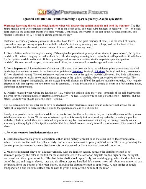
<strong>Ignition</strong> <strong>Installation</strong> <strong>Troubleshooting</strong> Tips/Frequently-Asked Questions<br />
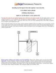
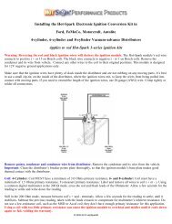
Warning: Reversing the red and black ignition wires will destroy the ignition module and void the warranty. The <strong>Hot</strong>-<br />
<strong>Spark</strong> module’s red wire connects to positive ( + or 15 on Bosch coil). The black wire connects to negative ( – or 1 on Bosch<br />
coil). Remove the condenser and its wire from vehicle. Connect any other wires to the coil in their original positions. This<br />
module is designed for 12V negative ground applications only.<br />
Customers occasionally return ignition kits to us that have failed. In the great majority of cases, it is the result of misuse,<br />
reversed or improper wiring or problems with the vehicle's electrical system (e.g., low voltage) and not the fault of the<br />
ignition kit. Here are the most common causes of failure (in the following order):<br />
1. Key is left on without the engine running. If the engine happened to stop in a position similar to points closed, the ignition<br />
module will continue charging the coil without the coil's discharging, resulting in excessive heat buildup in the coil, which can<br />
fry the ignition module and/or coil. If the engine happened to stop in a position similar to points open, the ignition<br />
module/coil circuit would be open, no current would flow, and there would be no damage to the electronics.<br />
2. Very Important: A low-resistance aftermarket coil is used that does not have the minimum primary resistance required<br />
by the ignition module, as stated in the instructions (minimum 3.0 ohms for 4-cyl, 1.5 ohms for 6-cyl and 8-cyl, assuming a<br />
12-Volt electrical system). The coil resistance regulates the current in the ignition module/coil circuit. Too little coil primary<br />
resistance resistance results in too much amperage going to the ignition module, which can overheat the electronics. The<br />
failure may not happen immediately, but the excess heat will shorten the life of the ignition module electronics. How long the<br />
electronics will last depends on how much heat is generated. It could be a matter of a couple of hours to a few hundred hours,<br />
depending on temperature.<br />
3. Polarity reversed when wiring the ignition kit (i.e., wiring the ignition kit to the + and - terminals of the coil, backwards).<br />
This will fry the ignition module's electronics immediately. The red <strong>Hot</strong><strong>Spark</strong> wire should go to the coil's + terminal and the<br />
black <strong>Hot</strong><strong>Spark</strong> wire should go to the coil's - terminal.<br />
It is not uncommon for an older car to have its electrical system modified at some time in its history, not always for the<br />
better. It is important to make sure the circuit to the ignition module is as it should be.<br />
Finally, it is possible for an ignition module to fail on its own, but this is the case in only a very small percent of the ignition<br />
kits that are returned. About 90 per cent of returned ignition kits usually test to be working perfectly, indicating a problem<br />
with the vehicle in which they were installed, improper wiring, bad connections or not setting the timing correctly with a<br />
stroboscopic timing light. Of the ignition modules that have failed, we can usually trace the reason to one of the causes listed<br />
above.<br />
A few other common installation problems are:<br />
1. Corroded and/or loose ground connection, either at the battery terminal or at the other end of the ground cable,<br />
where it makes contact with the vehicle body. Loose wire connections or poorly-spliced wires. The wire grounding the<br />
breaker plate, in vacuum-advance distributors, is not connected or has a loose or corroded connection.<br />
2. Magnets in magnet sleeve not aligned vertically with the ignition sensor, because the distributor shaft is not<br />
shimmed properly, the rotor is too tall for the distributor, etc. If the sensor or magnets are too high or low, no signal<br />
will result and the engine won't fire. The distributor shaft should spin freely, without dragging, when the distributor is<br />
out of the car, and magnet sleeve, rotor and distributor cap are installed. If the rotor is too tall, about one mm or so can<br />
be ground from the bottom of the rotor button, allowing the distributor shaft to spin freely. A belt sander or rough<br />
sandpaper on a flat, smooth surface can be used to grind a little off the bottom of the rotor.<br />
© 2005-2012 <strong>Hot</strong><strong>Spark</strong>
3. Distributor shaft height is too high or low, indicating too many or not enough spacing shims are installed in the<br />
distributor. Over time, the distributor shaft shims can wear out, causing up-and-down (axial) sloppy shaft movement<br />
and misalignment of the sensor and magnet sleeve.<br />
Here's a tip from a customer: Applies to 3BOS4U1, 3DEL4V1, 3DEL4U1, 3AUT4U1, 3PRE8U1, 3PRE8U2,<br />
3MAL8U1, etc. ignition kits: Had to add shims under breaker plate in order to get magnets in correct vertical<br />
alignment with ignition sensor. Added the equivalent of one small washer under each side of breaker plate. Engine ran<br />
fine after that. Before shimming, engine would barely idle and that was rough. Thought you may want to include this<br />
info with your instructions to save you the aggravation of people returning your product.<br />
4. The voltage, measured at the coil's + terminal, should be near battery voltage, or about +12 volts. If not, a wire can<br />
be run, on a temporary testing-only basis, directly from the battery's + terminal to the coil's + terminal. Do not leave<br />
this temporary wire attached for longer than 30 seconds or so, while the engine is not running.<br />
Wiring <strong>Installation</strong> Basics:<br />
1. Remove the points, condenser and the condenser's wire from the vehicle.<br />
2. Attach the red lead of a multi meter (voltmeter) to the coil's positive ( + ) terminal. Attach the voltmeter's black lead to<br />
engine ground. With the ignition switch on, engine not running, measure the voltage at the coil's positive terminal. The<br />
reading should be somewhere around +11 to +13 volts. If voltage is too low or there’s no reading, the battery’s terminals or<br />
ground connection may be corroded and need cleaning. Some vehicles have a resistor wire running from the ignition switch<br />
to the coil’s + terminal. If this resistor wire drops the voltage below 9 volts or so, you may need to run a non-resistor wire<br />
from the ignition switch to the coil’s + terminal or run a +12V wire directly from the ignition switch to the red <strong>Hot</strong>-<strong>Spark</strong><br />
ignition wire. Make sure that the ignition switch terminal to which you connect this wire has power only when the ignition<br />
switch is in the ON position.<br />
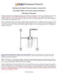
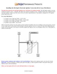
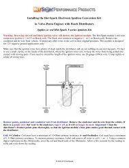
To get the ignition running initially, only these wires should be attached to the coil's + and - terminals:<br />
A. +12 volts from the ignition switch (+12-volt power source) to the coil's + terminal<br />
B. Red <strong>Hot</strong>-<strong>Spark</strong> wire to the coil's + terminal<br />
C. Black <strong>Hot</strong>-<strong>Spark</strong> wire to the coil's - terminal. DO NOT touch any +12-volt wire to the coil's - terminal.<br />
D. The automatic choke and fuel shut-off valve may also need to be attached to the coil's + terminal.<br />
E. Generally, only the black <strong>Hot</strong>-<strong>Spark</strong> wire is attached to the coil's - terminal. If a tachometer wire is usually attached to the<br />
coil's - terminal, don't attach it until the timing has been set and engine is running properly. No other wires should be<br />
connected to the coil's + and - terminals at this time.<br />
F. Attach a stroboscopic timing light to the spark plug wire of Cylinder number 1. With engine rotated to TDC (0 degrees) on<br />
the firing stroke of Cylinder number 1, ignition switch ON, turn the distributor until the timing light flashes. You may need to<br />
turn the distributor left or right a little, a little at a time, until the engine will stay running, so that you can set the timing with<br />
the engine running, using a stroboscopic timing light, according to factory specifications.<br />
G. For testing purposes, no other wires should be attached to the coil terminals, except for the center high-tension lead to the<br />
distributor cap.<br />
Attach a stroboscopic timing light to the spark plug wire of Cylinder number 1. With engine rotated to TDC on the firing<br />
stroke of Cylinder number 1, ignition switch ON, slowly turn the distributor clockwise or counter-clockwise until the timing<br />
light flashes. Tighten the distributor clamp a little, so that you can still turn the distributor by hand, but the distributor won't<br />
turn on its own. The rotor should be pointing to number 1 cylinder's spark plug wire.<br />
Start the engine. You may need to turn the distributor left or right a little, until the engine will stay running, so that you can<br />
set the timing with the engine running, using a stroboscopic timing light, according to factory specifications.<br />
© 2005-2012 <strong>Hot</strong><strong>Spark</strong>
Test Maximum Charging System Voltage: If the charging system voltage, measured at the coil’s positive terminal, is more<br />
than 14.0 volts at 2,500+ RPM, the voltage regulator likely needs replacing. Too much voltage can damage the ignition<br />
module and other electronic components. A maximum charging system voltage of 13.6 volts or so is plenty. A quick fix<br />
would be to wire an external ballast resistor between the ignition switch (+12 volt supply) and the coil's + terminal.<br />
Test Battery Voltage to Coil: With ignition switch ON, engine not running, check voltage at coil’s + terminal. The voltmeter<br />
should read somewhere around +11 to +13 volts. If voltage is too low or there’s no reading, the battery’s terminals or ground<br />
connection may be corroded and need cleaning or the battery may need charging. Some vehicles have a resistor wire running<br />
from the ignition switch to the coil’s + terminal. If this resistor wire drops the voltage below 9 volts or so, you may need to<br />
run a non-resistor wire from the ignition switch (+12-volt) to the coil’s + terminal or run a +12V wire directly from the<br />
ignition switch to the red <strong>Hot</strong>-<strong>Spark</strong> ignition wire. Make sure that the ignition switch terminal to which you connect this wire<br />
has power only when the ignition switch is in the ON position. Or, you can, for temporary testing purposes only, run a wire<br />
directly from the battery's + terminal to the coil's + terminal, the <strong>Hot</strong> <strong>Spark</strong> ignition's red wire to the coil's + terminal and the<br />
black <strong>Hot</strong>-<strong>Spark</strong> wire to the coil's - terminal. Do not leave the wire from the battery connected to the coil's + terminal for<br />
more than a minute or so without the engine running.<br />
Jump-starting the Vehicle: Use caution when jump-starting the vehicle. Connect the battery's + terminal to the other<br />
vehicle's battery's + terminal. Connect the negative (black) part of the jumper cable to engine ground points, such as a bolt on<br />
the engine block, on both vehicles. Do not turn the ignition switch to the ON position while the vehicle at the other end of the<br />
jumper cables is running. Charge your vehicle's battery with the other vehicle or with a battery charger and then remove the<br />
jumper cables or charger before turning on the ignition switch and starting your vehicle. If the ignition switch is in the ON<br />
position while both vehicles are running, the combined electrical surge resulting from both vehicles' charging systems being<br />
connected together with jumper cables could be enough to destroy the ignition module and/or other automotive electronic<br />
components.<br />
Air Gap between Magnet Sleeve and <strong>Ignition</strong> Sensor: Should be somewhere around 1 mm (.040 inches), but the exact gap<br />
is not critical, it can be more or less, as long as the magnet sleeve doesn't rub against the ignition sensor and you can see<br />
daylight between all spots on the magnet sleeve and ignition module.<br />
Turn on the ignition switch. With a stroboscopic light attached to Cylinder No. 1's spark plug wire, point the light at your eye.<br />
Have an assistant crank the engine over using the starter motor. The timing light should flash, again and again. If the<br />
stroboscopic timing light flashes, then the ignition module is working; the timing is simply out of adjustment.<br />
Timing: Set the timing to factory specifications, engine running, using a stroboscopic light attached to Cylinder number 1's<br />
spark plug wire. Because the electronic ignition module is mounted in a slightly different position than the points were, the<br />
distributor will possibly have to be turned as much as 20 to 30 degrees from where it was with points. You'll definitely have<br />
to reset the timing, using a stroboscopic timing light.<br />
Testing the ignition kit with a stroboscopic light : A simple way to test the ignition kit is to connect the stroboscopic timing<br />
light to number one cylinder's spark plug wire and point the light at your eye while someone cranks the engine over. The light<br />
should flash every second or more often. If the light flashes, then it's simply a matter of setting the timing with the engine<br />
running.<br />
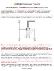
Coil: 4-Cylinder: Coil must have a minimum of 3.0 Ohms primary resistance. 6- and 8-cylinder: Coil must have a minimum<br />
of 1.5 Ohms primary resistance. To measure primary resistance: Label and remove all wires to coil ( + or - ). Using a common<br />
digital multimeter in the 200 Ω mode, cross the red and black leads of the Ohmmeter. Allow a few seconds for the reading to<br />
settle and write down the reading.<br />
Still in the 200 Ohm mode, measure between coil’s + and - terminals. Allow a few seconds for the reading to settle, until it<br />
stabilizes. Subtract the previous reading, taken with the leads crossed, to compensate for multimeter’s inherent resistance. Do<br />
not use a low-resistance coil, such as the MSD or Accel coil; they don’t have enough primary resistance for this application.<br />
Using a coil with too little primary resistance can cause the ignition module to overheat and misfire until it cools down<br />
again or fail, voiding the warranty.<br />
© 2005-2012 <strong>Hot</strong><strong>Spark</strong>
Check the voltage reading at the coil's + terminal, engine running, at 2,500+ RPM. If the voltage measures more than +14<br />
volts, you'll need to replace the voltage regulator, install a coil with 3.0 Ohms or more internal primary resistance or install a<br />
1.4 Ohm external ballast resistor between the ignition switch and the coil's + terminal. Charging voltage of 13.8 volts or so<br />
is plenty.<br />
For best performance, the coil should also have a 7,000 Ohms or more secondary resistance (measured from coil’s + or –<br />
terminal to center high tension terminal, in the 20K Ω mode of the Ohmmeter).<br />
Vacuum-advance Distributors: Check to see if the vacuum advance is working properly by sucking on the vacuum canister<br />
port. The breaker plate should move smoothly and freely.<br />
Magnet sleeve positioned too high: Situation: The fit between the distributor shaft and the magnet sleeve is especially tight<br />
and you can't slide the magnet sleeve down onto the distributor shaft all the way. The rotor rides too high, causing the<br />
distributor cap to wobble when you rotate the distributor shaft by hand. Fix: Rotate the magnet sleeve so that it lines up with<br />
the lobes of the distributor shaft cam and the magnet sleeve can slide down a bit. Install the rotor and tap, with a small<br />
plastic mallet, very gently, on the center of the rotor, until the magnet sleeve seats firmly onto the distributor shaft, over the<br />
distributor cam lobes. With the rotor and distributor cap installed, you should be able to rotate the distributor shaft without the<br />
distributor cap wobbling. The shaft should turn freely, without any feeling of drag. If the distributor cap still wobbles, you<br />
may need to adjust the number or thickness of the distributor shaft shims, inside the distributor.<br />
With some Chinese-made, knockoff 009 distributors, once the magnet sleeve and rotor have been installed and tapped down<br />
as far as they'll go, the rotor rides too high, causing the distributor shaft to turn stiffly and/or the distributor cap to wobble. In<br />
this case, the distributor needs to be disassembled, a distributor shaft shim removed from inside and a shim added to the<br />
outside of the distributor, onto the shaft, between the distributor body and the distributor shaft drive gear. Or a simpler<br />
solution would be to, using a belt sander or a piece of coarse sandpaper on a perfectly flat surface, sand off about 1 mm from<br />
the bottom of the rotor. You should use a micrometer to measure the before and after shortening rotor height.<br />
Magnet sleeve fit too loose: If the fit between the distributor shaft lobes and the magnet sleeve is too loose, the distributor<br />
shaft may be worn down from years of the points block rubbing on the distributor cam lobes, with accumulated dirt and grit,<br />
and/or insufficient lubrication. If the fit is especially loose, the best solution, short of replacing the distributor, may be to wrap<br />
the distributor shaft lobes, several times, with Teflon thread tape, before pressing the magnet sleeve down over the lobes. Too<br />
loose a fit between magnet sleeve and distributor cam lobes may result in erratic timing.<br />
Testing the <strong>Hot</strong>-<strong>Spark</strong> Red <strong>Ignition</strong> Module with an Ohmmeter<br />
To test the <strong>Hot</strong>-<strong>Spark</strong> red ignition module, you'll need a digital multi meter capable of measuring 20K Ohms. Almost any<br />
inexpensive digital multi meter should work. Harbor Freight sells them for US $5 to $20.<br />
Disconnect the two ignition module wires from the coil. Remove the magnet sleeve from the distributor and away from the<br />
ignition module.<br />
Set the multi meter to the 20K Ohms setting (not in the "auto" setting). Connect the red Ohmmeter lead to the red ignition<br />
module wire. Connect the black Ohmmeter lead to the black ignition module wire. The Ohmmeter should not register a<br />
connection (no change in reading, usually a reading of "1").<br />
Leaving the Ohmmeter in the 20K Ohm mode, and the red Ohmmeter lead connected to the red ignition module wire, touch<br />
the the black Ohmmeter lead to the ignition module's base plate (press firmly to ensure a good connection). The readout<br />
should be somewhere between 9.25K (9,250 Ohms) and 9.70K (9,700 Ohms).<br />
If there is any resistance between the red ignition module wire and the black ignition module wire, the ignition is likely<br />
defective or has been "fried" from reversed polarity or excess voltage or amperage. The digital Ohmmeter should read "1."<br />
Probable causes for ignition module failure include too much charging system voltage (more than 14 volts at 3,500+ RPM),<br />
using a coil with too little primary resistance (less than 3.0 Ohms for 4-cylinder, or less than 1.5 Ohms for 6- and 8-cylinder<br />
engines), reversing the red and black ignition wires on the coil, touching a +12 volt wire to the coil's - terminal while the<br />
ignition kit is connected to the coil or leaving the ignition switch in the ON position for more than a minute or so, without the<br />
engine running.<br />
© 2005-2012 <strong>Hot</strong><strong>Spark</strong>
Problems with Early 12V Signal Style Tachometers<br />
If your tachometer needle is bouncing or reading too high:<br />
If the car’s tachometer RPM reading is too high when the engine is running, or the tachometer works OK to a certain<br />
RPM, then stops or starts reading incorrectly, we recommend installing a resistor in line with the tachometer wire and<br />
coil's negative ( - ) terminal. This helps to lower the voltage spike at the coil's negative terminal to resemble a set of<br />
points, allowing the tachometer to read the ignition module's signal correctly.<br />
The type of tachometer will determine which resistor is needed. We have found that a 10K ohm ½ Watt resistor fixes<br />
most problems and suggest starting with one of these. If you find it doesn’t fix your problem, you might need to use<br />
one with higher resistance, like a 15K ohm ½ watt or 20K ohm ½ watt.<br />
A resistor will work in the vast majority of applications, but there are a small number of tachometer designs that will<br />
require a capacitor. We recommend using a .01 Microfarad 500VDC or 1000VDC capacitor.<br />
Using <strong>Hot</strong>-<strong>Spark</strong> <strong>Ignition</strong> with VDO Tachometer:<br />
Connect a diode #1N4005 between the negative terminal (- or 1) of the coil and the wire that goes to the tachometer.<br />
The cathode end (silver band) should be nearest the tachometer side, not the coil side. You should be able to buy a<br />
diode #1N4005 at Radio Shack or other electronic supply store.<br />
Click here for <strong>Hot</strong>-<strong>Spark</strong> <strong>Ignition</strong> <strong>Installation</strong> Instructions<br />
© 2005-2012 <strong>Hot</strong><strong>Spark</strong><br />
© 2005-2012 <strong>Hot</strong><strong>Spark</strong>