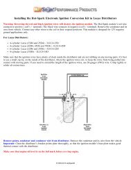
Instructions - Installing the Hot-Spark Ignition in Mallory Centrifugal ...
Instructions - Installing the Hot-Spark Ignition in Mallory Centrifugal ...
Instructions - Installing the Hot-Spark Ignition in Mallory Centrifugal ...

You also want an ePaper? Increase the reach of your titles
YUMPU automatically turns print PDFs into web optimized ePapers that Google loves.
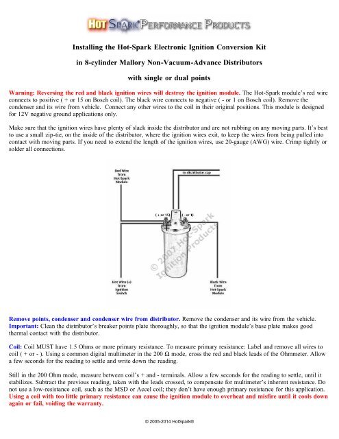
<strong>Install<strong>in</strong>g</strong> <strong>the</strong> <strong>Hot</strong>-<strong>Spark</strong> Electronic <strong>Ignition</strong> Conversion Kit<br />
<strong>in</strong> 8-cyl<strong>in</strong>der <strong>Mallory</strong> Non-Vacuum-Advance Distributors<br />
with s<strong>in</strong>gle or dual po<strong>in</strong>ts<br />
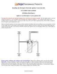
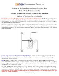
Warn<strong>in</strong>g: Revers<strong>in</strong>g <strong>the</strong> red and black ignition wires will destroy <strong>the</strong> ignition module. The <strong>Hot</strong>-<strong>Spark</strong> module’s red wire<br />
connects to positive ( + or 15 on Bosch coil). The black wire connects to negative ( - or 1 on Bosch coil). Remove <strong>the</strong><br />
condenser and its wire from vehicle. Connect any o<strong>the</strong>r wires to <strong>the</strong> coil <strong>in</strong> <strong>the</strong>ir orig<strong>in</strong>al positions. This module is designed<br />
for 12V negative ground applications only.<br />
Make sure that <strong>the</strong> ignition wires have plenty of slack <strong>in</strong>side <strong>the</strong> distributor and are not rubb<strong>in</strong>g on any mov<strong>in</strong>g parts. It’s best<br />
to use a small zip-tie, on <strong>the</strong> <strong>in</strong>side of <strong>the</strong> distributor, where <strong>the</strong> ignition wires exit, to keep <strong>the</strong> wires from be<strong>in</strong>g pulled <strong>in</strong>to<br />
contact with mov<strong>in</strong>g parts. If you need to extend <strong>the</strong> length of <strong>the</strong> ignition wires, use 20-gauge (AWG) wire. Crimp tightly or<br />
solder all connections.<br />
Remove po<strong>in</strong>ts, condenser and condenser wire from distributor. Remove <strong>the</strong> condenser and its wire from <strong>the</strong> vehicle.<br />
Important: Clean <strong>the</strong> distributor’s breaker po<strong>in</strong>ts plate thoroughly, so that <strong>the</strong> ignition module’s base plate makes good<br />
<strong>the</strong>rmal contact with <strong>the</strong> distributor.<br />
Coil: Coil MUST have 1.5 Ohms or more primary resistance. To measure primary resistance: Label and remove all wires to<br />
coil ( + or - ). Us<strong>in</strong>g a common digital multimeter <strong>in</strong> <strong>the</strong> 200 Ω mode, cross <strong>the</strong> red and black leads of <strong>the</strong> Ohmmeter. Allow<br />
a few seconds for <strong>the</strong> read<strong>in</strong>g to settle and write down <strong>the</strong> read<strong>in</strong>g.<br />
Still <strong>in</strong> <strong>the</strong> 200 Ohm mode, measure between coil’s + and - term<strong>in</strong>als. Allow a few seconds for <strong>the</strong> read<strong>in</strong>g to settle, until it<br />
stabilizes. Subtract <strong>the</strong> previous read<strong>in</strong>g, taken with <strong>the</strong> leads crossed, to compensate for multimeter’s <strong>in</strong>herent resistance. Do<br />
not use a low-resistance coil, such as <strong>the</strong> MSD or Accel coil; <strong>the</strong>y don’t have enough primary resistance for this application.<br />
Us<strong>in</strong>g a coil with too little primary resistance can cause <strong>the</strong> ignition module to overheat and misfire until it cools down<br />
aga<strong>in</strong> or fail, void<strong>in</strong>g <strong>the</strong> warranty.<br />
© 2005-2014 <strong>Hot</strong><strong>Spark</strong>®
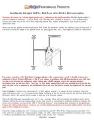
Check <strong>the</strong> voltage read<strong>in</strong>g at <strong>the</strong> coil's + term<strong>in</strong>al, eng<strong>in</strong>e runn<strong>in</strong>g, at 2,500+ RPM. If <strong>the</strong> voltage measures more than +14<br />
volts, you'll need to replace <strong>the</strong> voltage regulator, <strong>in</strong>stall a coil with 3.0 Ohms or more <strong>in</strong>ternal primary resistance or <strong>in</strong>stall a<br />
1.4 Ohm external ballast resistor between <strong>the</strong> ignition switch and <strong>the</strong> coil's + term<strong>in</strong>al.<br />
For best performance, <strong>the</strong> coil should also have a 7,000 Ohms or more secondary resistance (measured from coil’s + or –<br />
term<strong>in</strong>al to center high tension term<strong>in</strong>al, <strong>in</strong> <strong>the</strong> 20K Ω mode of <strong>the</strong> Ohmmeter).<br />
Test Maximum Charg<strong>in</strong>g System Voltage: If <strong>the</strong> charg<strong>in</strong>g system voltage, measured at <strong>the</strong> coil’s positive term<strong>in</strong>al, is more<br />
than 14 volts at 2,500+ RPM, <strong>the</strong> voltage regulator likely needs replac<strong>in</strong>g. Too much voltage can damage <strong>the</strong> ignition module<br />
and o<strong>the</strong>r electronic components.<br />
Test Battery Voltage to Coil: With ignition switch ON, eng<strong>in</strong>e not runn<strong>in</strong>g, check voltage at coil’s + term<strong>in</strong>al. The voltmeter<br />
should read somewhere around +11 to +13 volts. If voltage is too low or <strong>the</strong>re’s no read<strong>in</strong>g, <strong>the</strong> battery’s term<strong>in</strong>als or ground<br />
connection may be corroded and need clean<strong>in</strong>g or <strong>the</strong> battery may need charg<strong>in</strong>g. Some vehicles have a resistor wire runn<strong>in</strong>g<br />
from <strong>the</strong> ignition switch to <strong>the</strong> coil’s + term<strong>in</strong>al. If this resistor wire drops <strong>the</strong> voltage below 9 volts or so, you may need to<br />
run a non-resistor wire from <strong>the</strong> ignition switch to <strong>the</strong> coil’s + term<strong>in</strong>al or run a +12V wire directly from <strong>the</strong> ignition switch<br />
to <strong>the</strong> red <strong>Hot</strong>-<strong>Spark</strong> ignition wire. Make sure that <strong>the</strong> ignition switch term<strong>in</strong>al to which you connect this wire has power only<br />
when <strong>the</strong> ignition switch is <strong>in</strong> <strong>the</strong> ON position. Or, you can, for temporary test<strong>in</strong>g purposes only, run a wire directly from <strong>the</strong><br />
battery's + term<strong>in</strong>al to <strong>the</strong> coil's + term<strong>in</strong>al, <strong>the</strong> <strong>Hot</strong> <strong>Spark</strong> ignition's red wire to <strong>the</strong> coil's + term<strong>in</strong>al and <strong>the</strong> black <strong>Hot</strong>-<strong>Spark</strong><br />
wire to <strong>the</strong> coil's - term<strong>in</strong>al. Do not leave <strong>the</strong> wire from <strong>the</strong> battery connected to <strong>the</strong> coil's + term<strong>in</strong>al for more than a m<strong>in</strong>ute<br />
or so without <strong>the</strong> eng<strong>in</strong>e runn<strong>in</strong>g.<br />
<strong>Ignition</strong> Tim<strong>in</strong>g: Set <strong>the</strong> ignition tim<strong>in</strong>g, with a stroboscopic light, to <strong>the</strong> distributor’s factory specification. The difference <strong>in</strong><br />
distributor position with po<strong>in</strong>ts vs. electronic ignition can be as much as 30 degrees or so clockwise or counterclockwise, so<br />
you’ll def<strong>in</strong>itely have to reset <strong>the</strong> tim<strong>in</strong>g, with <strong>the</strong> eng<strong>in</strong>e runn<strong>in</strong>g, us<strong>in</strong>g a stroboscopic tim<strong>in</strong>g light.<br />
© 2005-2014 <strong>Hot</strong><strong>Spark</strong>®
3MAL8U1 Electronic <strong>Ignition</strong> Conversion Kit <strong>in</strong> <strong>Mallory</strong> Distributors<br />
Left: with two horizontal mount<strong>in</strong>g screws; Right: with two vertical mount<strong>in</strong>g screws<br />
Replaces Entire Breaker Plate - Never Adjust Po<strong>in</strong>ts or Tim<strong>in</strong>g Aga<strong>in</strong>!<br />
Electronic <strong>Ignition</strong> Conversion Kit for <strong>Centrifugal</strong>-advance 8-cyl<strong>in</strong>der <strong>Mallory</strong> Distributors<br />
1. Turn off <strong>the</strong> ignition switch and/or remove <strong>the</strong> ground strap from <strong>the</strong> battery. Though not absolutely necessary, it is<br />
probably easiest overall to remove <strong>the</strong> distributor from <strong>the</strong> car before <strong>in</strong>stall<strong>in</strong>g <strong>the</strong> <strong>Hot</strong>-<strong>Spark</strong> module. If <strong>the</strong> contacts <strong>in</strong> <strong>the</strong><br />
<strong>in</strong>side of <strong>the</strong> distributor cap are worn or damaged, replace <strong>the</strong> distributor cap. Replace <strong>the</strong> rotor if it’s worn.<br />
2. Turn <strong>the</strong> eng<strong>in</strong>e over, by hand, until <strong>the</strong> rotor po<strong>in</strong>ts to <strong>the</strong> number one spark plug wire. Make a mark on <strong>the</strong> rim of<br />
<strong>the</strong> distributor body, where <strong>the</strong> rotor is po<strong>in</strong>t<strong>in</strong>g. You can <strong>the</strong>n remove <strong>the</strong> distributor and replace it <strong>in</strong> <strong>the</strong> same<br />
position as before.<br />
3. Remove distributor cap, leav<strong>in</strong>g <strong>the</strong> plug wires <strong>in</strong> place, unless replac<strong>in</strong>g <strong>the</strong> distributor cap as well.<br />
4. Make a mark with a felt pen on <strong>the</strong> rim of <strong>the</strong> distributor, close to <strong>the</strong> center of <strong>the</strong> po<strong>in</strong>ts. The new red ignition module<br />
should align, somewhat, with this mark. Remove breaker plate, po<strong>in</strong>ts, condenser and <strong>the</strong>ir wires from <strong>the</strong> distributor.<br />
Because <strong>the</strong> <strong>Hot</strong>-<strong>Spark</strong> kit does not modify <strong>the</strong> distributor, <strong>the</strong> old breaker plate with po<strong>in</strong>ts and condenser can be re<strong>in</strong>stalled<br />
at a later time, if desired.<br />
5. Clean any grease or dirt from <strong>the</strong> distributor shaft's po<strong>in</strong>ts cam. You may need to brush <strong>the</strong> distributor lobes with a brass<br />
brush to help <strong>the</strong> magnet sleeve to seat fully.<br />
6. Replace <strong>the</strong> entire old breaker plate with <strong>the</strong> new 3MAL8U1 "breaker plate," align<strong>in</strong>g its semi-circle cutout <strong>in</strong> <strong>the</strong> same<br />
position as with <strong>the</strong> old breaker plate. Use <strong>the</strong> same screws <strong>in</strong> <strong>the</strong> same holes as <strong>the</strong> old breaker plate, 180 degrees apart.<br />
3MAL8U1 Electronic ignition kit for 8-cyl<strong>in</strong>der <strong>Mallory</strong> distributors with centrifugal advance only. Not for vacuum-advance<br />
distributors. Replaces entire breaker plate. Remove old breaker plate, along with po<strong>in</strong>ts and condenser. Remove wir<strong>in</strong>g post<br />
from side of distributor body. Insert <strong>the</strong> two breaker plate mount<strong>in</strong>g screws through <strong>the</strong> screw holes, located 180 degrees<br />
apart, on both sides of <strong>the</strong> distributor body. Start thread<strong>in</strong>g <strong>the</strong> washers and nuts on <strong>the</strong> two mount<strong>in</strong>g screws on <strong>the</strong> outside of<br />
<strong>the</strong> distributor body, but leave enough slack to <strong>in</strong>stall <strong>the</strong> new ignition plate. If <strong>the</strong> breaker plate is secured to <strong>the</strong> distributor<br />
body with two vertical screws, use <strong>the</strong> orig<strong>in</strong>al screws to secure <strong>the</strong> new ignition plate. Tighten <strong>the</strong> screws, so that <strong>the</strong> new<br />
© 2005-2014 <strong>Hot</strong><strong>Spark</strong>®
ignition plate rema<strong>in</strong>s stationary.<br />
6. Install magnet sleeve, with <strong>the</strong> larger open<strong>in</strong>g down. Turn <strong>the</strong> magnet sleeve left and right, while push<strong>in</strong>g down firmly,<br />
until you can feel <strong>the</strong> distributor shaft cam lobes l<strong>in</strong>e up with <strong>the</strong> flat spots <strong>in</strong>side <strong>the</strong> magnet sleeve. Press down firmly until<br />
<strong>the</strong> magnet sleeve slides as far down as it will. Install <strong>the</strong> rotor on top of <strong>the</strong> magnet sleeve, mak<strong>in</strong>g sure <strong>the</strong> rotor is aligned<br />
with <strong>the</strong> slot <strong>in</strong> <strong>the</strong> top of <strong>the</strong> distributor shaft. The rotor should slide all <strong>the</strong> way down and lock <strong>in</strong>to place, so that it cannot<br />
turn <strong>in</strong>dependently of <strong>the</strong> distributor shaft. If you can still turn <strong>the</strong> rotor <strong>in</strong>dependently of <strong>the</strong> distributor shaft, <strong>the</strong> magnet<br />
sleeve and/or rotor is not seated all <strong>the</strong> way down. You may need to brush <strong>the</strong> lobes of <strong>the</strong> distributor shaft with a brass brush<br />
to ensure that <strong>the</strong> magnet sleeve can seat fully. It might also be necessary to <strong>in</strong>stall an old rotor on top of <strong>the</strong> magnet sleeve<br />
and tap lightly on <strong>the</strong> center of <strong>the</strong> rotor until <strong>the</strong> magnet sleeve is seated fully.<br />
7. Adjust <strong>the</strong> two <strong>Hot</strong>-<strong>Spark</strong> ignition wires so that <strong>the</strong>y have plenty of slack <strong>in</strong>side <strong>the</strong> distributor and <strong>the</strong>y’re not rubb<strong>in</strong>g on<br />
any mov<strong>in</strong>g parts. Pull <strong>the</strong> two ignition wires, along with <strong>the</strong> grommet, through <strong>the</strong> hole <strong>in</strong> <strong>the</strong> side of <strong>the</strong> distributor.<br />
8. Use a zip tie around <strong>the</strong> ignition wires on <strong>the</strong> <strong>in</strong>side of <strong>the</strong> distributor, next to where <strong>the</strong> wires exit through <strong>the</strong> hole, to<br />
keep <strong>the</strong> wires from be<strong>in</strong>g pulled <strong>in</strong>to contact with mov<strong>in</strong>g parts <strong>in</strong>side <strong>the</strong> distributor.<br />
9. Re<strong>in</strong>stall <strong>the</strong> distributor.<br />
10. The <strong>Hot</strong>-<strong>Spark</strong> module’s red wire connects to positive ( + ). The black wire connects to negative ( - ). DO NOT reverse<br />
<strong>the</strong> polarity of <strong>the</strong>se wires or <strong>the</strong> ignition module will be destroyed.<br />
11. Check all wire connections, <strong>in</strong>clud<strong>in</strong>g <strong>the</strong> two <strong>Hot</strong>-<strong>Spark</strong> wires and <strong>the</strong> spark plug and coil high-tension wires. If you need<br />
to extend <strong>the</strong> length of <strong>the</strong> wires, use 18- or 20-gauge wire. We recommend solder<strong>in</strong>g all splices and connections, if you can,<br />
or crimp all connections tightly. Make doubly sure that all wires are connected to <strong>the</strong> proper term<strong>in</strong>als, etc. before<br />
reconnect<strong>in</strong>g <strong>the</strong> battery or turn<strong>in</strong>g <strong>the</strong> ignition switch to <strong>the</strong> ON position. Make sure that all connectors are snug. Reconnect<br />
<strong>the</strong> battery and set <strong>the</strong> distributor tim<strong>in</strong>g statically. DO NOT touch any +12 volt wire to <strong>the</strong> coil's - term<strong>in</strong>al or to <strong>the</strong> black<br />
wire of <strong>the</strong> ignition module.<br />
12. You can set <strong>the</strong> tim<strong>in</strong>g statically to about 0° (TDC) at first, so that <strong>the</strong> eng<strong>in</strong>e will start. Static tim<strong>in</strong>g, us<strong>in</strong>g an ord<strong>in</strong>ary<br />
12-volt test lamp, will not work. Attach a stroboscopic tim<strong>in</strong>g light to <strong>the</strong> spark plug wire of Cyl<strong>in</strong>der number 1. You may<br />
need to rotate <strong>the</strong> distributor, a little at a time, right or left, to enable <strong>the</strong> eng<strong>in</strong>e to start and rema<strong>in</strong> runn<strong>in</strong>g. Time <strong>the</strong> eng<strong>in</strong>e<br />
with a stroboscopic light, with <strong>the</strong> eng<strong>in</strong>e runn<strong>in</strong>g, accord<strong>in</strong>g to factory specifications.<br />
Sett<strong>in</strong>g Tim<strong>in</strong>g<br />
Sett<strong>in</strong>g Tim<strong>in</strong>g: This will probably be <strong>the</strong> last time you have to set <strong>the</strong> tim<strong>in</strong>g for a long time, so it’s worth it to spend <strong>the</strong><br />
extra time and effort to set <strong>the</strong> tim<strong>in</strong>g absolutely spot-on accurately. An eng<strong>in</strong>e with its tim<strong>in</strong>g set to perfection will start with<br />
<strong>the</strong> slightest bump of <strong>the</strong> starter and purr like a kitten at idle – someth<strong>in</strong>g to make you feel good every time you start <strong>the</strong><br />
eng<strong>in</strong>e.<br />
TDC = Top Dead Center, or 0° BTDC = Before Top Dead Center ATDC = After Top Dead Center<br />
Distributor Cap and Rotor: Stock <strong>Mallory</strong> rotors and distributor caps work f<strong>in</strong>e with <strong>the</strong> <strong>Hot</strong>-<strong>Spark</strong> module. A worn,<br />
corroded or scored distributor cap and/or rotor is often <strong>the</strong> cause of <strong>the</strong> tim<strong>in</strong>g jump<strong>in</strong>g around erratically at idle. We<br />
recommend <strong>in</strong>stall<strong>in</strong>g a new distributor cap and rotor when convert<strong>in</strong>g from po<strong>in</strong>ts to electronic ignition.<br />
<strong>Spark</strong> Plug Gap: With <strong>the</strong> <strong>Hot</strong>-<strong>Spark</strong> ignition kit, <strong>the</strong> stock spark plug gap specification is f<strong>in</strong>e. For rac<strong>in</strong>g purposes, you can<br />
<strong>in</strong>crease <strong>the</strong> spark plug gap by about .005 <strong>in</strong>ches, or .12 mm.<br />
<strong>Hot</strong>-<strong>Spark</strong> <strong>Ignition</strong> and MSD 6 Series Wir<strong>in</strong>g Diagram: www.<strong>Hot</strong>-<strong>Spark</strong>.com/<strong>Hot</strong>-<strong>Spark</strong>-MSD-6-series.jpg<br />
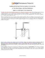
Wir<strong>in</strong>g Installation Basics:<br />
1. Remove po<strong>in</strong>ts, condenser and condenser wire from <strong>the</strong> vehicle.<br />
2. Attach <strong>the</strong> red lead of a voltmeter to <strong>the</strong> coil's positive ( + ) term<strong>in</strong>al. Attach <strong>the</strong> voltmeter's black lead to eng<strong>in</strong>e ground.<br />
© 2005-2014 <strong>Hot</strong><strong>Spark</strong>®
With <strong>the</strong> ignition switch on, eng<strong>in</strong>e not runn<strong>in</strong>g, measure <strong>the</strong> voltage at <strong>the</strong> coil's positive ( + ) term<strong>in</strong>al. The read<strong>in</strong>g should<br />
be somewhere around +11 to +13 volts. If voltage is too low or <strong>the</strong>re’s no read<strong>in</strong>g, <strong>the</strong> battery’s term<strong>in</strong>als or ground<br />
connection may be corroded and need clean<strong>in</strong>g. Some vehicles have a resistor wire runn<strong>in</strong>g from <strong>the</strong> ignition switch to <strong>the</strong><br />
coil’s + term<strong>in</strong>al. If this resistor wire drops <strong>the</strong> voltage below 9 volts or so, you may need to run a non-resistor wire from <strong>the</strong><br />
ignition switch to <strong>the</strong> coil’s + term<strong>in</strong>al or run a +12V wire directly from <strong>the</strong> ignition switch to <strong>the</strong> red <strong>Hot</strong>-<strong>Spark</strong> ignition<br />
wire. Make sure that <strong>the</strong> ignition switch term<strong>in</strong>al to which you connect this wire has power only when <strong>the</strong> ignition switch is <strong>in</strong><br />
<strong>the</strong> ON position.<br />
To get <strong>the</strong> ignition runn<strong>in</strong>g <strong>in</strong>itially, only <strong>the</strong>se wires should be attached to <strong>the</strong> coil's + and - term<strong>in</strong>als:<br />
A. +12 volts from <strong>the</strong> ignition switch to <strong>the</strong> coil's + term<strong>in</strong>al<br />
B. Red <strong>Hot</strong>-<strong>Spark</strong> wire to <strong>the</strong> coil's + term<strong>in</strong>al<br />
C. Black <strong>Hot</strong>-<strong>Spark</strong> wire to <strong>the</strong> coil's - term<strong>in</strong>al. DO NOT connect any +12-volt wire to <strong>the</strong> coil's - term<strong>in</strong>al. Connect<br />
only <strong>the</strong> black <strong>Hot</strong>-<strong>Spark</strong> ignition wire to <strong>the</strong> coil's - term<strong>in</strong>al.<br />
D. The automatic choke and fuel shut-off valve may also need to be attached to <strong>the</strong> coil's + term<strong>in</strong>al.<br />
E. Generally, only <strong>the</strong> black <strong>Hot</strong>-<strong>Spark</strong> wire is attached to <strong>the</strong> coil's - term<strong>in</strong>al. If a tachometer wire is usually attached to <strong>the</strong><br />
coil's - term<strong>in</strong>al, don't attach it until <strong>the</strong> tim<strong>in</strong>g has been set and eng<strong>in</strong>e is runn<strong>in</strong>g properly. No o<strong>the</strong>r wires should be<br />
connected to <strong>the</strong> coil's + and - term<strong>in</strong>als at this time.<br />
F. Static tim<strong>in</strong>g, us<strong>in</strong>g an ord<strong>in</strong>ary 12-volt test lamp, will not work. Attach a stroboscopic tim<strong>in</strong>g light to <strong>the</strong> spark plug<br />
wire of Cyl<strong>in</strong>der number 1. With eng<strong>in</strong>e rotated to TDC (0 degrees) on <strong>the</strong> fir<strong>in</strong>g stroke of Cyl<strong>in</strong>der number 1, ignition switch<br />
ON, turn <strong>the</strong> distributor until <strong>the</strong> tim<strong>in</strong>g light flashes. You may need to turn <strong>the</strong> distributor left or right, a little at a time, until<br />
<strong>the</strong> eng<strong>in</strong>e will stay runn<strong>in</strong>g, so that you can set <strong>the</strong> tim<strong>in</strong>g with <strong>the</strong> eng<strong>in</strong>e runn<strong>in</strong>g, us<strong>in</strong>g a stroboscopic tim<strong>in</strong>g light,<br />
accord<strong>in</strong>g to factory specifications.<br />
G. For test<strong>in</strong>g purposes, no o<strong>the</strong>r wires should be attached to <strong>the</strong> coil term<strong>in</strong>als, except for <strong>the</strong> center high-tension lead to <strong>the</strong><br />
distributor cap.<br />
Attach a stroboscopic tim<strong>in</strong>g light to <strong>the</strong> spark plug wire of Cyl<strong>in</strong>der number 1. With eng<strong>in</strong>e rotated to TDC on <strong>the</strong> fir<strong>in</strong>g<br />
stroke of Cyl<strong>in</strong>der number 1, ignition switch ON, slowly turn <strong>the</strong> distributor clockwise or counter-clockwise until <strong>the</strong> tim<strong>in</strong>g<br />
light flashes. Tighten <strong>the</strong> distributor clamp a little, so that you can still turn <strong>the</strong> distributor by hand, but <strong>the</strong> distributor won't<br />
turn on its own. The rotor should be po<strong>in</strong>t<strong>in</strong>g to number 1 cyl<strong>in</strong>der's spark plug wire.<br />
Start <strong>the</strong> eng<strong>in</strong>e. You may need to turn <strong>the</strong> distributor left or right a little, until <strong>the</strong> eng<strong>in</strong>e will stay runn<strong>in</strong>g, so that you can<br />
set <strong>the</strong> tim<strong>in</strong>g with <strong>the</strong> eng<strong>in</strong>e runn<strong>in</strong>g, us<strong>in</strong>g a stroboscopic tim<strong>in</strong>g light, accord<strong>in</strong>g to factory specifications.<br />
Us<strong>in</strong>g <strong>Hot</strong>-<strong>Spark</strong> <strong>Ignition</strong> with VDO Tachometer:<br />
Connect a diode #1N4005 between <strong>the</strong> negative term<strong>in</strong>al (- or 1) of <strong>the</strong> coil and <strong>the</strong> wire that goes to <strong>the</strong> tachometer.<br />
The cathode end (silver band) should be nearest <strong>the</strong> tachometer side, not <strong>the</strong> coil side. You should be able to buy a<br />
diode #1N4005 at Radio Shack or o<strong>the</strong>r electronic supply store.<br />
Latest On-L<strong>in</strong>e Installation <strong>Instructions</strong>: www.<strong>Hot</strong>-<strong>Spark</strong>.com/<strong>Install<strong>in</strong>g</strong>-<strong>Hot</strong>-<strong>Spark</strong>-<strong>Mallory</strong>.pdf<br />
Problems with Installation See www.<strong>Hot</strong>-<strong>Spark</strong>.com/Troubleshoot<strong>in</strong>g.pdf<br />
OMC Mar<strong>in</strong>e Eng<strong>in</strong>e Shift Assist Adapter: Click here for wir<strong>in</strong>g diagram: www.<strong>Hot</strong>-<br />
<strong>Spark</strong>.com/OMC-Shift-Assist-Adapter.jpg<br />
© 2005-2014 <strong>Hot</strong><strong>Spark</strong> ®<br />
© 2005-2014 <strong>Hot</strong><strong>Spark</strong>®