Installing The Hot-Spark SVDA034 Distributor With 3BOS4U1
Installing The Hot-Spark SVDA034 Distributor With 3BOS4U1
Installing The Hot-Spark SVDA034 Distributor With 3BOS4U1

Create successful ePaper yourself
Turn your PDF publications into a flip-book with our unique Google optimized e-Paper software.
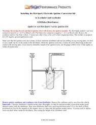
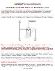
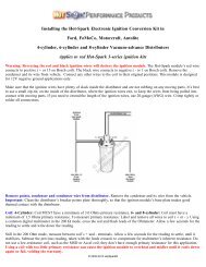
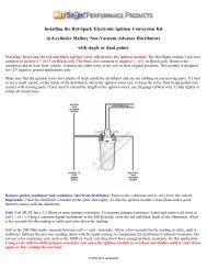
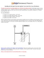
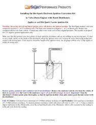
<strong>Installing</strong> the <strong>Hot</strong>-<strong>Spark</strong> <strong>SVDA034</strong> <strong>Distributor</strong> with <strong>3BOS4U1</strong> Electronic Ignition<br />
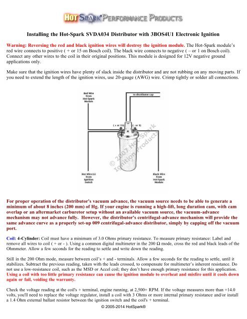
Warning: Reversing the red and black ignition wires will destroy the ignition module. <strong>The</strong> <strong>Hot</strong>-<strong>Spark</strong> module’s<br />
red wire connects to positive ( + or 15 on Bosch coil). <strong>The</strong> black wire connects to negative ( – or 1 on Bosch coil).<br />
Connect any other wires to the coil in their original positions. This module is designed for 12V negative ground<br />
applications only.<br />
Make sure that the ignition wires have plenty of slack inside the distributor and are not rubbing on any moving parts. If<br />
you need to extend the length of the ignition wires, use 20-gauge (AWG) wire. Crimp tightly or solder all connections.<br />
For proper operation of the distributor's vacuum advance, the vacuum source needs to be able to generate a<br />
minimum of about 8 inches (200 mm) of Hg. If your engine is running a high-lift, long duration cam, with cam<br />
overlap or an aftermarket carburetor setup without an available vacuum source, the vacuum-advance<br />
mechanism may not advance fully. However, the distributor's centrifugal-advance mechanism will provide the<br />
same advance curve as a properly set-up 009 centrifugal-advance distributor, simply by capping off the vacuum<br />
port.<br />
Coil: 4-Cylinder: Coil must have a minimum of 3.0 Ohms primary resistance. To measure primary resistance: Label and<br />
remove all wires to coil ( + or - ). Using a common digital multimeter in the 200 Ω mode, cross the red and black leads of the<br />
Ohmmeter. Allow a few seconds for the reading to settle and write down the reading.<br />
Still in the 200 Ohm mode, measure between coil’s + and - terminals. Allow a few seconds for the reading to settle, until it<br />
stabilizes. Subtract the previous reading, taken with the leads crossed, to compensate for multimeter’s inherent resistance. Do<br />
not use a low-resistance coil, such as the MSD or Accel coil; they don’t have enough primary resistance for this application.<br />
Using a coil with too little primary resistance can cause the ignition module to overheat and misfire until it cools down<br />
again or fail, voiding the warranty.<br />
Check the voltage reading at the coil's + terminal, engine running, at 2,500+ RPM. If the voltage measures more than +14.0<br />
volts, you'll need to replace the voltage regulator, install a coil with 3 Ohms or more internal primary resistance and/or install<br />
a 1.4 Ohm external ballast resistor between the ignition switch and the coil's + terminal.<br />
© 2005-2014 <strong>Hot</strong><strong>Spark</strong>®
For best performance, the coil should also have 7,000 Ohms or more secondary resistance (measured from coil’s + or –<br />
terminal to center high tension terminal, in the 20K Ω mode of the Ohmmeter).<br />
Test the charging system's maximum voltage: If the charging system voltage, measured at the coil's positive<br />
terminal, is more than 14.2 volts at 2,500+ RPM, the voltage regulator likely needs replacing. Too much voltage can<br />
damage the ignition module and other electronic components.<br />
Test Battery Voltage to Coil: <strong>With</strong> ignition switch ON, engine not running, check voltage at coil’s + terminal. <strong>The</strong><br />
voltmeter should read somewhere around +11 to +13 volts. If voltage is too low or there’s no reading, the battery’s<br />
terminals or ground connection may be corroded and need cleaning or the battery may need charging. Some vehicles<br />
have a resistor wire running from the ignition switch to the coil’s + terminal. If this resistor wire drops the voltage<br />
below 9 volts or so, you may need to run a non-resistor wire from the ignition switch to the coil’s + terminal or run a<br />
+12V wire directly from the ignition switch to the red <strong>Hot</strong>-<strong>Spark</strong> ignition wire. Make sure that the ignition switch<br />
terminal to which you connect this wire has power only when the ignition switch is in the ON position. Or, you can,<br />
for temporary testing purposes only, run a wire directly from the battery's + terminal to the coil's + terminal, the <strong>Hot</strong><br />
<strong>Spark</strong> ignition's red wire to the coil's + terminal and the black <strong>Hot</strong>-<strong>Spark</strong> wire to the coil's - terminal. Do not leave the<br />
wire from the battery connected to the coil's + terminal for more than a minute or so without the engine running.<br />
Can use these standard Bosch replacement parts:<br />
Rotor: 04 033<br />
<strong>Distributor</strong> Cap: 03 010<br />
Vacuum Can: 07 059<br />
Compatible Carburetors: <strong>The</strong> following carburetors should produce the proper amount of vacuum for use with the<br />
SVDA 034 distributor (if they are fitted with a vacuum port):<br />
Weber DFAV or DFEV<br />
Solex 30PICT-3<br />
Bocar 30/31<br />
Single or dual IDF<br />
DRLA<br />
ICT<br />
Solex 30/31<br />
1972-1974 VW bus with dual carburetors<br />
Kadron<br />
Solex 34PICT series<br />
If your car has Kadron or ICT carbs, connect the vacuum hose to at least one carburetor. If your car has dual IDF or<br />
DRLA carbs, run a vacuum hose to both carburetors, "T" them together and then run the vacuum hose to the SVDA<br />
034's vacuum port.<br />
If your '71 VW Bus or '71-'74 VW Beetle/Ghia/Thing has the original dual-vacuum distributor and you replace it with<br />
the SVDA 034, you'll need to plug (cap off) the carburetor's retard vacuum port, which is the port located closest to<br />
you as you're looking at the carburetor from the rear of the car. Use the advance vacuum port, located on the left side<br />
of the 34PICT carburetor.<br />
This distributor requires a 12-volt, negative ground electrical system.<br />
Make sure that engine oil level is on the full mark before revving engine!<br />
Finding Top Dead Center on a VW Type I engine: http://www.vw-resource.com/find_tdc.html#pulley<br />
© 2005-2014 <strong>Hot</strong><strong>Spark</strong>®
Which is Number One Cylinder?<br />
You can rotate the position of the spark plug leads in the distributor cap, as needed, so that the arrangement of the<br />
ignition wires and the position of the vacuum canister best suits your particular application. Any of the distributor<br />
cap’s four spark plug wire positions can be for number one cylinder, as long as the firing order remains 1-4-3-2,<br />
clockwise. Cylinder number 1 for Type I VW engines is normally at about the eleven o'clock position, when looking<br />
down on the engine from above. For VW Type IV engines (1972-83 USA VW bus), Cylinder No. 1 is normally at<br />
about the five o'clock position. Each cylinder firing position is 90° from the next or last, including Cylinder number 3<br />
(No. 3 is not retarded).<br />
Lubricating <strong>Distributor</strong><br />
Occasionally lubricate the distributor shaft and its bushing and the swinging centrifugal advance weights in the bottom<br />
of the distributor. A small amount of heavy oil, such as 90W hypoid, synthetic heavy transmission oil or heavy motor<br />
oil works well for lubricating the distributor. Don't use a thin solvent, such as WD-40, for lubrication, as its lubricating<br />
qualities won't last for long. Clean up any excess oil or grease.<br />
<strong>Installing</strong> <strong>Distributor</strong> in VW Type I Engine - Beetle, Ghia, Thing, 1950-71 Bus (USA)<br />
Before removing the old distributor, rotate the crankshaft to TDC (0°) on the compression stroke for Cylinder number<br />
1. You can locate Cylinder number 1's firing position like this:<br />
Remove the right-side valve cover, exposing the valves of Cylinders number 1 and 2 (Cylinder 1 is closest to the front<br />
of the car). <strong>The</strong> exhaust valves for Cylinders number 1 and 2 are closest to the front and rear of the car, respectively<br />
(on the outside). Cylinders number 1 and 2 intake valves are next to each other (on the inside). Rotate the engine<br />
clockwise, by hand, until you see Number 1 cylinder's exhaust valve open. Keep rotating the engine until the intake<br />
valve opens and then closes. Turn the engine by hand, clockwise, until the TDC (0°) notch in the crankshaft pulley<br />
wheel is lined up with where the two engine case halves join. <strong>The</strong> Woodruff key that fastens the pulley to the<br />
crankshaft should be at the nine o'clock position. <strong>The</strong> old distributor's rotor should be pointed to Cylinder number 1's<br />
spark plug wire. That is TDC (0°) on the compression stroke for Cylinder number 1.<br />
Another method of finding Cylinder number 1's compression stroke is by removing the spark plug from Cylinder<br />
number 1, and holding your finger or thumb over the empty spark plug socket. Turn the crankshaft pulley clockwise,<br />
by hand, until you can feel compressed air rushing from spark plug hole (it's then on the compression stroke). Turn the<br />
pulley a little, until the TDC (0°) notch lines up with where the two engine case halves join or the crankshaft pulley's<br />
Woodruff key is at the nine o'clock position. <strong>The</strong> rotor should be pointing at the spark plug wire for Cylinder number<br />
1.<br />
<strong>The</strong> air-cooled VW's cylinders are arranged as follows:<br />
Front of Car<br />
3 1<br />
4 2<br />
Rear of Car<br />
As you look at the exhaust and intake valves from the car's right side:<br />
Cylinder 2 Cylinder 1<br />
Exhaust Intake Intake Exhaust<br />
© 2005-2014 <strong>Hot</strong><strong>Spark</strong>®
<strong>The</strong> rotor should be pointing to No. 1 Cylinder's spark plug wire. Note the location of the tab on the rim of the<br />
distributor cap and orient it so that it aligns with the notch in the rim of the old distributor's body. Remove each spark<br />
plug wire from the old distributor cap, one-at-a-time, and insert it into the new distributor cap in the same location and<br />
order (cylinders 1-4-3-2, clockwise).<br />
Remove the old distributor and remove its clamp. Slide the distributor clamp onto the new distributor, before you fit<br />
the O-Ring to the distributor shaft. Now slide the O-Ring onto the distributor shaft and into its groove. Coat the<br />
distributor shaft and O-Ring with motor oil before sliding it into its hole. Look down into the engine's distributor hole<br />
to see how the distributor drive slot is oriented and turn the distributor shaft to match it. Make sure that the anti-chatter<br />
spring is in place, down in the center of the hole. Insert the distributor shaft into the hole. You might need to tap the<br />
distributor's rim gently to get the O-Ring started into the hole. Work the shaft down all the way, turning the rotor<br />
gently, as needed, until the distributor shaft gear settles into its slot and the rotor will no longer turn.<br />
Place the cap on the new distributor. <strong>The</strong> rotor should point to Cylinder number 1. If not, move the spark plug wires in<br />
the distributor cap around, until the rotor points to the spark plug wire for Cylinder number 1. Cylinders 4, 3 and 2<br />
spark plug wires should follow, in a clockwise direction (1-4-3-2 firing order).<br />
If the rotor doesn't point to number 1 cylinder, the distributor drive pinion may be installed incorrectly. It will need to<br />
be removed from the distributor shaft hole with a special extraction tool and reinstalled so that its slot is oriented<br />
correctly (see VW repair manual for illustration).<br />
Timing the SVDA 034 <strong>Distributor</strong><br />
TDC = Top Dead Center, or 0° BTDC = Before Top Dead Center ATDC = After Top Dead Center<br />
34PICT Carburetor: Use the vacuum port on the LEFT side of the 34PICT carburetor (advance port). Use vacuum<br />
hose with an inside diameter of 4mm.<br />
<strong>The</strong> only way to set the timing correctly is with a stroboscopic light, while the engine is running. Set the timing at 30-<br />
32° BTDC @ 3,500+ RPM, vacuum hose disconnected and plugged. Do not advance the timing further than 32°<br />
BTDC at full advance (vacuum hose disconnected, no load on engine, 3,500+ RPM).<br />
6. Timing: <strong>The</strong> position of the distributor will be as much as 30 degrees, CW or CCW, from where it was with points.<br />
Use a strobe timing light to set timing, with engine running. If you had a 0 231 178 009 distributor installed previously,<br />
the position of the SVDA distributor will be about 45 degrees from where it was with the 009, as the 009 is a nonstandard,<br />
aftermarket distributor that was never installed in any vehicle at any VW factory.<br />
You can locate the 30° BTDC spot on a stock VW Type I crankshaft pulley, which has a 175 mm (6-7/8 in.) diameter,<br />
by measuring, clockwise, from top dead center, around the circumference of the pulley, 45.8 mm, or 1-13/16 in. Make<br />
a small white paint mark there. That's about 30° BTDC.<br />
Connect the hose from the vacuum source to the distributor's vacuum canister. <strong>The</strong> vacuum source is normally the<br />
carburetor body or the fuel injection's throttle body. For proper operation of the distributor's vacuum advance, the<br />
vacuum source needs to generate a minimum of 8 inches (200mm) of Hg. If the distributor you're replacing is a dualvacuum-advance<br />
model, cap off the larger retard vacuum port of the carburetor, and connect the vacuum hose from the<br />
left side of the carburetor only (Solex 30- or 34-PICT carburetor).<br />
After you connect the vacuum hose, timing should be about 40-42° BTDC at full advance (vacuum hose connected, no<br />
load on engine, 3,500+ RPM).<br />
You can locate the 42° BTDC spot on a stock VW Type I crankshaft pulley, which has a 175 mm (6-7/8 in.) diameter,<br />
by measuring, clockwise, from top dead center, around the circumference of the pulley, about 64 mm, or 2.52 in. Make<br />
a small white paint mark there. That's about 42° BTDC.<br />
Click here for printable VW Type I crankshaft pulley degree template for SVDA 034 distributor.<br />
© 2005-2014 <strong>Hot</strong><strong>Spark</strong>®
See www.<strong>Hot</strong>-<strong>Spark</strong>.com/<strong>Installing</strong>-<strong>Hot</strong>-<strong>Spark</strong>.pdf for more detailed information.<br />
Vacuum Hose: <strong>The</strong> outside diameter of a VW/Solex carburetor's vacuum port is 4.4mm. Vacuum hose with an inside<br />
diameter of 4mm is normally used to connect the carburetor's vacuum port and the distributor's vacuum canister.<br />
Wiring Installation Basics:<br />
1. Remove points, condenser and condenser wire from the vehicle.<br />
2. Attach the red lead of a voltmeter to the coil's positive ( + or 15) terminal. Attach the voltmeter's black lead to engine<br />
ground. <strong>With</strong> the ignition switch on, engine not running, measure the voltage at the coil's positive ( + or 15) terminal. <strong>The</strong><br />
reading should be somewhere around +11 to +13 volts. If voltage is too low or there’s no reading, the battery’s terminals or<br />
ground connection may be corroded and need cleaning. Some vehicles have a resistor wire running from the ignition switch<br />
to the coil’s + terminal. If this resistor wire drops the voltage below 9 volts or so, you may need to run a non-resistor wire<br />
from the ignition switch to the coil’s + terminal or run a +12V wire directly from the ignition switch to the red <strong>Hot</strong>-<strong>Spark</strong><br />
ignition wire. Make sure that the ignition switch terminal to which you connect this wire has power only when the ignition<br />
switch is in the ON position.<br />
To get the ignition running initially, only these wires should be attached to the coil's + (15) and - (1) terminals:<br />
A. +12 volts from the ignition switch to the coil's + terminal<br />
B. Red <strong>Hot</strong>-<strong>Spark</strong> wire to the coil's + terminal<br />
C. Black <strong>Hot</strong>-<strong>Spark</strong> wire to the coil's - terminal. DO NOT connect any +12-volt wire to the coil's - terminal. Connect<br />
only the black <strong>Hot</strong>-<strong>Spark</strong> ignition wire to the coil's - terminal.<br />
D. <strong>The</strong> automatic choke and fuel shut-off valve may also need to be attached to the coil's + terminal.<br />
E. Generally, only the black <strong>Hot</strong>-<strong>Spark</strong> wire is attached to the coil's - terminal. If a tachometer wire is usually attached to the<br />
coil's - terminal, don't attach it until the timing has been set and engine is running properly. No other wires should be<br />
connected to the coil's + and - terminals at this time.<br />
F. Static timing, using an ordinary 12-volt test lamp, will not work, as with points. Attach a stroboscopic timing light to<br />
the spark plug wire of Cylinder number 1. <strong>With</strong> engine rotated to 7.5° BTDC, on the firing stroke of Cylinder number 1,<br />
ignition switch ON, turn the distributor until the stroboscopic timing light flashes. Tighten the distributor clamp a little, so<br />
that you can still turn the distributor by hand, but the distributor won't turn on its own. You may need to turn the distributor<br />
left or right, a little at a time, until the engine will stay running, so that you can set the timing with the engine running, using<br />
a stroboscopic timing light.<br />
G. For testing purposes, no other wires should be attached to the coil terminals, except for the center high-tension lead to the<br />
distributor cap.<br />
<strong>The</strong> rotor should be pointing to number 1 cylinder's spark plug wire. <strong>The</strong> position of the rotor will be different than the<br />
position of a 009 (which is non-standard) distributor's rotor. If necessary, you can rotate the wires, as long as the firing<br />
order remains the same: 1-4-3-2, clockwise.<br />
Start the engine. You may need to turn the distributor left or right a little, until the engine will stay running, so that you<br />
can set the timing with the engine running, using a stroboscopic timing light. <strong>With</strong> vacuum hose disconnected and<br />
plugged, the timing should be set to 30-32 degrees BTDC at 3,500+ RPM. <strong>With</strong> the vacuum hose connected, timing<br />
should not exceed 42-44 degrees BTDC at 3,500+ RPM.<br />
Using <strong>Hot</strong>-<strong>Spark</strong> Ignition with VDO Tachometer: Connect a diode #1N4005 between the negative terminal (- or 1)<br />
of the coil and the wire that goes to the tachometer. <strong>The</strong> cathode end (silver band) should be nearest the tachometer<br />
side, not the coil side. You should be able to buy a diode #1N4005 at Radio Shack or other electronic supply store.<br />
© 2005-2014 <strong>Hot</strong><strong>Spark</strong>®
<strong>Hot</strong>-<strong>Spark</strong> Ignition and MSD 6 Series Wiring Diagram: www.<strong>Hot</strong>-<strong>Spark</strong>.com/<strong>Hot</strong>-<strong>Spark</strong>-MSD-6-series.jpg<br />
Troubleshooting/FAQ: Having installation problems? Click here<br />
Email Us: info@<strong>Hot</strong>-<strong>Spark</strong>.com<br />
© 2005-2014 <strong>Hot</strong><strong>Spark</strong> ®<br />
© 2005-2014 <strong>Hot</strong><strong>Spark</strong>®