Installing the Hot-Spark Ignition in Ford - Hot-Spark Performance ...
Installing the Hot-Spark Ignition in Ford - Hot-Spark Performance ...
Installing the Hot-Spark Ignition in Ford - Hot-Spark Performance ...
- No tags were found...

Create successful ePaper yourself
Turn your PDF publications into a flip-book with our unique Google optimized e-Paper software.
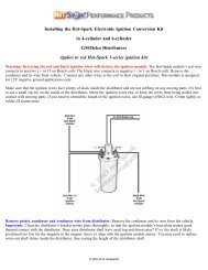
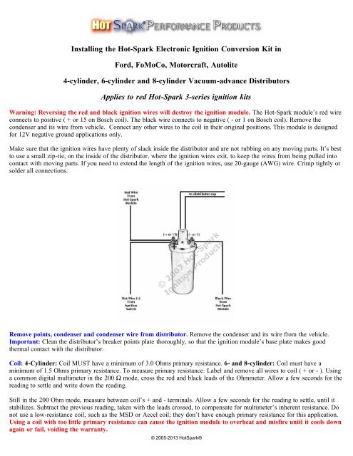
<strong>Install<strong>in</strong>g</strong> <strong>the</strong> <strong>Hot</strong>-<strong>Spark</strong> Electronic <strong>Ignition</strong> Conversion Kit <strong>in</strong><strong>Ford</strong>, FoMoCo, Motorcraft, Autolite4-cyl<strong>in</strong>der, 6-cyl<strong>in</strong>der and 8-cyl<strong>in</strong>der Vacuum-advance DistributorsApplies to red <strong>Hot</strong>-<strong>Spark</strong> 3-series ignition kitsWarn<strong>in</strong>g: Revers<strong>in</strong>g <strong>the</strong> red and black ignition wires will destroy <strong>the</strong> ignition module. The <strong>Hot</strong>-<strong>Spark</strong> module’s red wireconnects to positive ( + or 15 on Bosch coil). The black wire connects to negative ( - or 1 on Bosch coil). Remove <strong>the</strong>condenser and its wire from vehicle. Connect any o<strong>the</strong>r wires to <strong>the</strong> coil <strong>in</strong> <strong>the</strong>ir orig<strong>in</strong>al positions. This module is designedfor 12V negative ground applications only.Make sure that <strong>the</strong> ignition wires have plenty of slack <strong>in</strong>side <strong>the</strong> distributor and are not rubb<strong>in</strong>g on any mov<strong>in</strong>g parts. It’s bestto use a small zip-tie, on <strong>the</strong> <strong>in</strong>side of <strong>the</strong> distributor, where <strong>the</strong> ignition wires exit, to keep <strong>the</strong> wires from be<strong>in</strong>g pulled <strong>in</strong>tocontact with mov<strong>in</strong>g parts. If you need to extend <strong>the</strong> length of <strong>the</strong> ignition wires, use 20-gauge (AWG) wire. Crimp tightly orsolder all connections.Remove po<strong>in</strong>ts, condenser and condenser wire from distributor. Remove <strong>the</strong> condenser and its wire from <strong>the</strong> vehicle.Important: Clean <strong>the</strong> distributor’s breaker po<strong>in</strong>ts plate thoroughly, so that <strong>the</strong> ignition module’s base plate makes good<strong>the</strong>rmal contact with <strong>the</strong> distributor.Coil: 4-Cyl<strong>in</strong>der: Coil MUST have a m<strong>in</strong>imum of 3.0 Ohms primary resistance. 6- and 8-cyl<strong>in</strong>der: Coil must have am<strong>in</strong>imum of 1.5 Ohms primary resistance. To measure primary resistance: Label and remove all wires to coil ( + or - ). Us<strong>in</strong>ga common digital multimeter <strong>in</strong> <strong>the</strong> 200 Ω mode, cross <strong>the</strong> red and black leads of <strong>the</strong> Ohmmeter. Allow a few seconds for <strong>the</strong>read<strong>in</strong>g to settle and write down <strong>the</strong> read<strong>in</strong>g.Still <strong>in</strong> <strong>the</strong> 200 Ohm mode, measure between coil’s + and - term<strong>in</strong>als. Allow a few seconds for <strong>the</strong> read<strong>in</strong>g to settle, until itstabilizes. Subtract <strong>the</strong> previous read<strong>in</strong>g, taken with <strong>the</strong> leads crossed, to compensate for multimeter’s <strong>in</strong>herent resistance. Donot use a low-resistance coil, such as <strong>the</strong> MSD or Accel coil; <strong>the</strong>y don’t have enough primary resistance for this application.Us<strong>in</strong>g a coil with too little primary resistance can cause <strong>the</strong> ignition module to overheat and misfire until it cools downaga<strong>in</strong> or fail, void<strong>in</strong>g <strong>the</strong> warranty.© 2005-2013 <strong>Hot</strong><strong>Spark</strong>®
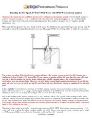
Check <strong>the</strong> voltage read<strong>in</strong>g at <strong>the</strong> coil's + term<strong>in</strong>al, eng<strong>in</strong>e runn<strong>in</strong>g, at 2,500+ RPM. If <strong>the</strong> voltage measures more than +14volts, you'll need to replace <strong>the</strong> voltage regulator, <strong>in</strong>stall a coil with 3.0 Ohms or more <strong>in</strong>ternal primary resistance or <strong>in</strong>stall a1.4 Ohm external ballast resistor between <strong>the</strong> ignition switch and <strong>the</strong> coil's + term<strong>in</strong>al. For best performance, <strong>the</strong> coil shouldalso have a 7,000 Ohms or more secondary resistance (measured from coil’s + or – term<strong>in</strong>al to center high tension term<strong>in</strong>al, <strong>in</strong><strong>the</strong> 20K Ω mode of <strong>the</strong> Ohmmeter).Test Maximum Charg<strong>in</strong>g System Voltage: If <strong>the</strong> charg<strong>in</strong>g system voltage, measured at <strong>the</strong> coil’s positive term<strong>in</strong>al, is morethan 14 volts at 2,500+ RPM, <strong>the</strong> voltage regulator likely needs replac<strong>in</strong>g. Too much voltage can damage <strong>the</strong> ignition moduleand o<strong>the</strong>r electronic components.Test Battery Voltage to Coil: With ignition switch ON, eng<strong>in</strong>e not runn<strong>in</strong>g, check voltage at coil’s + term<strong>in</strong>al. The voltmetershould read somewhere around +11 to +13 volts. If voltage is too low or <strong>the</strong>re’s no read<strong>in</strong>g, <strong>the</strong> battery’s term<strong>in</strong>als or groundconnection may be corroded and need clean<strong>in</strong>g or <strong>the</strong> battery may need charg<strong>in</strong>g. Some vehicles have a resistor wire runn<strong>in</strong>gfrom <strong>the</strong> ignition switch to <strong>the</strong> coil’s + term<strong>in</strong>al. If this resistor wire drops <strong>the</strong> voltage below 9 volts or so, you may need torun a non-resistor wire from <strong>the</strong> ignition switch to <strong>the</strong> coil’s + term<strong>in</strong>al or run a +12V wire directly from <strong>the</strong> ignition switchto <strong>the</strong> red <strong>Hot</strong>-<strong>Spark</strong> ignition wire. Make sure that <strong>the</strong> ignition switch term<strong>in</strong>al to which you connect this wire has power onlywhen <strong>the</strong> ignition switch is <strong>in</strong> <strong>the</strong> ON position. Or, you can, for temporary test<strong>in</strong>g purposes only, run a wire directly from <strong>the</strong>battery's + term<strong>in</strong>al to <strong>the</strong> coil's + term<strong>in</strong>al, <strong>the</strong> <strong>Hot</strong> <strong>Spark</strong> ignition's red wire to <strong>the</strong> coil's + term<strong>in</strong>al and <strong>the</strong> black <strong>Hot</strong>-<strong>Spark</strong>wire to <strong>the</strong> coil's - term<strong>in</strong>al. Do not leave <strong>the</strong> wire from <strong>the</strong> battery connected to <strong>the</strong> coil's + term<strong>in</strong>al for more than a m<strong>in</strong>uteor so without <strong>the</strong> eng<strong>in</strong>e runn<strong>in</strong>g.Air Gap between Magnet Sleeve and <strong>Ignition</strong> Sensor: If you need to <strong>in</strong>crease air gap slightly, hold ignition base plate awayfrom distributor shaft while tighten<strong>in</strong>g set screw and/or loosen <strong>the</strong> two Allen head screws and retighten screws while lightlypry<strong>in</strong>g ignition module away from magnet sleeve. Do not over-torque <strong>the</strong>se Allen screws. Black magnet sleeve should not rubaga<strong>in</strong>st red ignition module, but exact gap is not critical. In rare <strong>in</strong>stances, it may be necessary to gently pry red ignitionmodule away from black magnet sleeve to keep <strong>the</strong>m from rubb<strong>in</strong>g toge<strong>the</strong>r.<strong>Ignition</strong> Tim<strong>in</strong>g: Set <strong>the</strong> ignition tim<strong>in</strong>g, eng<strong>in</strong>e runn<strong>in</strong>g, with a stroboscopic light, to <strong>the</strong> distributor’s factory specification.The difference <strong>in</strong> distributor position with po<strong>in</strong>ts vs. electronic ignition can be as much as 30 degrees or so clockwise orcounterclockwise, so you’ll def<strong>in</strong>itely have to reset <strong>the</strong> tim<strong>in</strong>g.Left: 3FOR8U1 <strong>in</strong> <strong>Ford</strong> 8-cyl<strong>in</strong>der Vacuum-advance DistributorRight: 3FOR6U1 <strong>in</strong> <strong>Ford</strong> 6-cyl<strong>in</strong>der Vacuum-advance Distributor© 2005-2013 <strong>Hot</strong><strong>Spark</strong>®
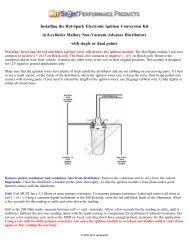
Magnet sleeve positioned too high: Situation: The fit between <strong>the</strong> distributor shaft and <strong>the</strong> magnet sleeve is especially tightand you can't slide <strong>the</strong> magnet sleeve down onto <strong>the</strong> distributor shaft all <strong>the</strong> way. The rotor rides too high, caus<strong>in</strong>g <strong>the</strong>distributor cap to wobble when you rotate <strong>the</strong> distributor shaft. Fix: Rotate <strong>the</strong> magnet sleeve so that it l<strong>in</strong>es up with <strong>the</strong> lobesof <strong>the</strong> distributor shaft cam and <strong>the</strong> magnet sleeve can slide down a bit. Install <strong>the</strong> rotor and tap, with a small hammer or asoft rubber mallet, very gently, on <strong>the</strong> center of <strong>the</strong> rotor, until <strong>the</strong> magnet sleeve seats firmly onto <strong>the</strong> distributor shaft, over<strong>the</strong> distributor cam lobes. With <strong>the</strong> rotor and distributor cap <strong>in</strong>stalled, you should be able to rotate <strong>the</strong> distributor shaft without<strong>the</strong> distributor cap wobbl<strong>in</strong>g. If <strong>the</strong> distributor cap still wobbles, you may need to adjust <strong>the</strong> number or thickness of <strong>the</strong>distributor shaft shims or <strong>the</strong> placement of <strong>the</strong> distributor shaft gear.Magnet sleeve fit too loose: If <strong>the</strong> fit between <strong>the</strong> distributor shaft lobes and <strong>the</strong> magnet sleeve is too loose, <strong>the</strong> distributorshaft may be worn down from years of <strong>the</strong> po<strong>in</strong>ts block rubb<strong>in</strong>g on <strong>the</strong> distributor cam lobes, with accumulated dirt and grit,and/or <strong>in</strong>sufficient lubrication. If <strong>the</strong> fit is especially loose, <strong>the</strong> only solution, short of replac<strong>in</strong>g <strong>the</strong> distributor, may be toclean <strong>the</strong> distributor cam lobes thoroughly with alcohol and wrap <strong>the</strong> lobes with a s<strong>in</strong>gle wrap of high-quality electrical tape,before press<strong>in</strong>g <strong>the</strong> magnet sleeve down over <strong>the</strong> lobes. Too loose a fit between magnet sleeve and distributor cam lobes mayresult <strong>in</strong> erratic tim<strong>in</strong>g.You can adjust <strong>the</strong> air gap by loosen<strong>in</strong>g <strong>the</strong> two ignition module screws and mov<strong>in</strong>g <strong>the</strong> module closer to or far<strong>the</strong>r from <strong>the</strong>magnet sleeve. The air gap should be sufficient to keep <strong>the</strong> magnet sleeve from rubb<strong>in</strong>g on <strong>the</strong> ignition module. An ideal gap8. Check to see if <strong>the</strong> vacuum advance is work<strong>in</strong>g properly by suck<strong>in</strong>g on or apply<strong>in</strong>g vacuum to <strong>the</strong> vacuum canister port.The breaker plate should move smoothly and freely.9. Adjust <strong>the</strong> two <strong>Hot</strong>-<strong>Spark</strong> ignition wires, as <strong>in</strong> <strong>the</strong> above photo, so that <strong>the</strong>y have plenty of slack <strong>in</strong>side <strong>the</strong> distributor and<strong>the</strong>y’re not rubb<strong>in</strong>g on any mov<strong>in</strong>g parts.10. Install <strong>the</strong> distributor cap.11. Re<strong>in</strong>stall <strong>the</strong> distributor.12. The <strong>Hot</strong>-<strong>Spark</strong> module’s red wire connects to positive ( + ). The black wire connects to negative ( - ). DO NOT reverse<strong>the</strong> polarity of <strong>the</strong>se wires or <strong>the</strong> ignition module will be destroyed.13. Check all wire connections, <strong>in</strong>clud<strong>in</strong>g <strong>the</strong> two <strong>Hot</strong>-<strong>Spark</strong> wires and <strong>the</strong> spark plug and coil high-tension wires. If you needto extend <strong>the</strong> length of <strong>the</strong> wires, use 18- or 20-gauge wire. We recommend solder<strong>in</strong>g all splices and connections, if you can,or crimp all connections tightly. Make doubly sure that all wires are connected to <strong>the</strong> proper term<strong>in</strong>als, etc. beforereconnect<strong>in</strong>g <strong>the</strong> battery or turn<strong>in</strong>g <strong>the</strong> ignition switch to <strong>the</strong> ON position. Make sure that all connectors are snug. Reconnect<strong>the</strong> battery and set <strong>the</strong> distributor tim<strong>in</strong>g statically. It's a good idea to secure <strong>the</strong> wires <strong>in</strong>side <strong>the</strong> distributor, next to where<strong>the</strong>y exit, with a zip tie, to keep <strong>the</strong> wires from be<strong>in</strong>g pulled <strong>in</strong>to contact with <strong>the</strong> sp<strong>in</strong>n<strong>in</strong>g magnet sleeve or rotor.14. You can set <strong>the</strong> tim<strong>in</strong>g statically to about 0° (TDC) at first, so that <strong>the</strong> eng<strong>in</strong>e will start. You may need to tweak <strong>the</strong>distributor, a little at a time, right or left, to enable <strong>the</strong> eng<strong>in</strong>e to start and rema<strong>in</strong> runn<strong>in</strong>g. Time <strong>the</strong> eng<strong>in</strong>e with astroboscopic light, with <strong>the</strong> eng<strong>in</strong>e runn<strong>in</strong>g, accord<strong>in</strong>g to factory specifications.Sett<strong>in</strong>g Tim<strong>in</strong>g: This will probably be <strong>the</strong> last time you have to set <strong>the</strong> tim<strong>in</strong>g for a long time, so it’s worth it to spend <strong>the</strong>extra time and effort to set <strong>the</strong> tim<strong>in</strong>g absolutely spot-on accurately. An eng<strong>in</strong>e with its tim<strong>in</strong>g set to perfection will start with<strong>the</strong> slightest bump of <strong>the</strong> starter and purr like a kitten at idle – someth<strong>in</strong>g to make you feel good every time you get <strong>in</strong> <strong>the</strong>car.TDC = Top Dead Center, or 0° BTDC = Before Top Dead Center ATDC = After Top Dead CenterDistributor Cap and Rotor: Stock <strong>Ford</strong> rotors and distributor caps work f<strong>in</strong>e with <strong>the</strong> <strong>Hot</strong>-<strong>Spark</strong> module. A worn, corrodedor scored distributor cap and/or rotor is often <strong>the</strong> cause of <strong>the</strong> tim<strong>in</strong>g jump<strong>in</strong>g around erratically at idle. With <strong>the</strong> <strong>Hot</strong>-<strong>Spark</strong>electronic ignition <strong>in</strong>stalled <strong>in</strong> place of po<strong>in</strong>ts, several times as much voltage surges through <strong>the</strong> rotor to <strong>the</strong> distributor capterm<strong>in</strong>al contacts. While <strong>the</strong> rotor and distributor cap may have functioned alright with po<strong>in</strong>ts, <strong>the</strong> <strong>in</strong>creased stra<strong>in</strong> of double<strong>the</strong> voltage may be too much for <strong>the</strong> old, worn rotor and distributor cap. We recommend <strong>in</strong>stall<strong>in</strong>g a new distributor cap androtor when convert<strong>in</strong>g from po<strong>in</strong>ts to electronic ignition.© 2005-2013 <strong>Hot</strong><strong>Spark</strong>®
Replac<strong>in</strong>g <strong>Ford</strong> 8-Cyl<strong>in</strong>der Breaker PlateEmail from a Customer: Breaker Plate Spr<strong>in</strong>g ModificationI purchased one of <strong>the</strong>se V8 <strong>Ford</strong> 3FOR8U1 kits from you. Had trouble gett<strong>in</strong>g right breaker plate from Carquest and<strong>Ford</strong>. They both came with <strong>the</strong> high spr<strong>in</strong>g on <strong>the</strong> plates. I ended up convert<strong>in</strong>g <strong>the</strong> orig<strong>in</strong>al one by remov<strong>in</strong>g <strong>the</strong> clipcarefully and cutt<strong>in</strong>g <strong>the</strong> spr<strong>in</strong>g down to 1/4” tall and carefully driv<strong>in</strong>g <strong>the</strong> reta<strong>in</strong>er down on <strong>the</strong> shaft to hold it <strong>in</strong> place(I did not cut <strong>the</strong> shaft).© 2005-2013 <strong>Hot</strong><strong>Spark</strong>®
While I had it apart, I cleaned it and re-lubed <strong>the</strong> plates and mov<strong>in</strong>g parts with Syl-Glide from NAPA. Modified <strong>the</strong>vacuum advance lever with a gr<strong>in</strong>der for clearance around <strong>the</strong> module and put it all back toge<strong>the</strong>r with <strong>the</strong> <strong>Hot</strong>-<strong>Spark</strong>kit and it works great! Thought I would share <strong>the</strong> idea of trimm<strong>in</strong>g <strong>the</strong> spr<strong>in</strong>g <strong>in</strong> case you have a customer run <strong>in</strong>to <strong>the</strong>same problem. Thanks aga<strong>in</strong>, DuWayne <strong>in</strong> West Columbia, SC.Problems with Installation? See www.<strong>Hot</strong>-<strong>Spark</strong>.com/Troubleshoot<strong>in</strong>g.pdfLatest On-L<strong>in</strong>e Installation Instructions: www.<strong>Hot</strong>-<strong>Spark</strong>.com/<strong>Install<strong>in</strong>g</strong>-<strong>Hot</strong>-<strong>Spark</strong>-<strong>Ford</strong>.pdf© 2005-2013 <strong>Hot</strong><strong>Spark</strong> ®© 2005-2013 <strong>Hot</strong><strong>Spark</strong>®