Installing the Hot-Spark Ignition in Ford - Hot-Spark Performance ...
Installing the Hot-Spark Ignition in Ford - Hot-Spark Performance ...
Installing the Hot-Spark Ignition in Ford - Hot-Spark Performance ...
- No tags were found...

Create successful ePaper yourself
Turn your PDF publications into a flip-book with our unique Google optimized e-Paper software.
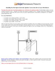
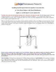
Check <strong>the</strong> voltage read<strong>in</strong>g at <strong>the</strong> coil's + term<strong>in</strong>al, eng<strong>in</strong>e runn<strong>in</strong>g, at 2,500+ RPM. If <strong>the</strong> voltage measures more than +14volts, you'll need to replace <strong>the</strong> voltage regulator, <strong>in</strong>stall a coil with 3.0 Ohms or more <strong>in</strong>ternal primary resistance or <strong>in</strong>stall a1.4 Ohm external ballast resistor between <strong>the</strong> ignition switch and <strong>the</strong> coil's + term<strong>in</strong>al. For best performance, <strong>the</strong> coil shouldalso have a 7,000 Ohms or more secondary resistance (measured from coil’s + or – term<strong>in</strong>al to center high tension term<strong>in</strong>al, <strong>in</strong><strong>the</strong> 20K Ω mode of <strong>the</strong> Ohmmeter).Test Maximum Charg<strong>in</strong>g System Voltage: If <strong>the</strong> charg<strong>in</strong>g system voltage, measured at <strong>the</strong> coil’s positive term<strong>in</strong>al, is morethan 14 volts at 2,500+ RPM, <strong>the</strong> voltage regulator likely needs replac<strong>in</strong>g. Too much voltage can damage <strong>the</strong> ignition moduleand o<strong>the</strong>r electronic components.Test Battery Voltage to Coil: With ignition switch ON, eng<strong>in</strong>e not runn<strong>in</strong>g, check voltage at coil’s + term<strong>in</strong>al. The voltmetershould read somewhere around +11 to +13 volts. If voltage is too low or <strong>the</strong>re’s no read<strong>in</strong>g, <strong>the</strong> battery’s term<strong>in</strong>als or groundconnection may be corroded and need clean<strong>in</strong>g or <strong>the</strong> battery may need charg<strong>in</strong>g. Some vehicles have a resistor wire runn<strong>in</strong>gfrom <strong>the</strong> ignition switch to <strong>the</strong> coil’s + term<strong>in</strong>al. If this resistor wire drops <strong>the</strong> voltage below 9 volts or so, you may need torun a non-resistor wire from <strong>the</strong> ignition switch to <strong>the</strong> coil’s + term<strong>in</strong>al or run a +12V wire directly from <strong>the</strong> ignition switchto <strong>the</strong> red <strong>Hot</strong>-<strong>Spark</strong> ignition wire. Make sure that <strong>the</strong> ignition switch term<strong>in</strong>al to which you connect this wire has power onlywhen <strong>the</strong> ignition switch is <strong>in</strong> <strong>the</strong> ON position. Or, you can, for temporary test<strong>in</strong>g purposes only, run a wire directly from <strong>the</strong>battery's + term<strong>in</strong>al to <strong>the</strong> coil's + term<strong>in</strong>al, <strong>the</strong> <strong>Hot</strong> <strong>Spark</strong> ignition's red wire to <strong>the</strong> coil's + term<strong>in</strong>al and <strong>the</strong> black <strong>Hot</strong>-<strong>Spark</strong>wire to <strong>the</strong> coil's - term<strong>in</strong>al. Do not leave <strong>the</strong> wire from <strong>the</strong> battery connected to <strong>the</strong> coil's + term<strong>in</strong>al for more than a m<strong>in</strong>uteor so without <strong>the</strong> eng<strong>in</strong>e runn<strong>in</strong>g.Air Gap between Magnet Sleeve and <strong>Ignition</strong> Sensor: If you need to <strong>in</strong>crease air gap slightly, hold ignition base plate awayfrom distributor shaft while tighten<strong>in</strong>g set screw and/or loosen <strong>the</strong> two Allen head screws and retighten screws while lightlypry<strong>in</strong>g ignition module away from magnet sleeve. Do not over-torque <strong>the</strong>se Allen screws. Black magnet sleeve should not rubaga<strong>in</strong>st red ignition module, but exact gap is not critical. In rare <strong>in</strong>stances, it may be necessary to gently pry red ignitionmodule away from black magnet sleeve to keep <strong>the</strong>m from rubb<strong>in</strong>g toge<strong>the</strong>r.<strong>Ignition</strong> Tim<strong>in</strong>g: Set <strong>the</strong> ignition tim<strong>in</strong>g, eng<strong>in</strong>e runn<strong>in</strong>g, with a stroboscopic light, to <strong>the</strong> distributor’s factory specification.The difference <strong>in</strong> distributor position with po<strong>in</strong>ts vs. electronic ignition can be as much as 30 degrees or so clockwise orcounterclockwise, so you’ll def<strong>in</strong>itely have to reset <strong>the</strong> tim<strong>in</strong>g.Left: 3FOR8U1 <strong>in</strong> <strong>Ford</strong> 8-cyl<strong>in</strong>der Vacuum-advance DistributorRight: 3FOR6U1 <strong>in</strong> <strong>Ford</strong> 6-cyl<strong>in</strong>der Vacuum-advance Distributor© 2005-2013 <strong>Hot</strong><strong>Spark</strong>®