Split-type air conditioners Mitsubishi Electric MSZ-FH25VE, MSZ ...
Split-type air conditioners Mitsubishi Electric MSZ-FH25VE, MSZ ...
Split-type air conditioners Mitsubishi Electric MSZ-FH25VE, MSZ ...

Create successful ePaper yourself
Turn your PDF publications into a flip-book with our unique Google optimized e-Paper software.
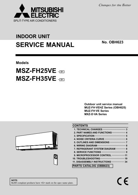
SPLIT-TYPE AIR CONDITIONERS<br />
INDOOR UNIT<br />
SERVICE MANUAL<br />
Models<br />
<strong>MSZ</strong>-<strong>FH25VE</strong> - E1<br />
<strong>MSZ</strong>-FH35VE - E1<br />
NOTE:<br />
RoHS compliant products have mark on the spec name plate.<br />
CONTENTS<br />
No. OBH623<br />
Outdoor unit service manual<br />
MUZ-FH·VEHZ Series (OBH625)<br />
MUZ-FH·VE Series<br />
MXZ-D·VA Series<br />
1. TECHNICAL CHANGES ··································· 3<br />
2. PART NAMES AND FUNCTIONS ····················· 4<br />
3. SPECIFICATION ················································ 5<br />
4. NOISE CRITERIA CURVE ································ 6<br />
5. OUTLINES AND DIMENSIONS ························ 7<br />
6. WIRING DIAGRAM ············································ 8<br />
7. REFRIGERANT SYSTEM DIAGRAM ··············· 8<br />
8. SERVICE FUNCTIONS ····································· 9<br />
9. MICROPROCESSOR CONTROL ····················11<br />
10. TROUBLESHOOTING ····································· 19<br />
11. DISASSEMBLY INSTRUCTIONS ···················· 34<br />
PARTS CATALOG (OBB623)
Use the specifi ed refrigerant only<br />
Never use any refrigerant other than that specified.<br />
Doing so may cause a burst, an explosion, or fire when the unit is being used, serviced, or disposed of.<br />
Correct refrigerant is specified in the manuals and on the spec labels provided with our products.<br />
We will not be held responsible for mechanical failure, system malfunction, unit breakdown or accidents caused by<br />
failure to follow the instructions.<br />
<br />
Prepare the proper tools.<br />
Prepare the proper protectors.<br />
Provide adequate ventilation.<br />
After stopping the operation of the <strong>air</strong> conditioner, turn off the power-supply breaker and remove the power plug.<br />
Discharge the capacitor before the work involving the electric parts.<br />
<br />
Do not perform the work involving the electric parts with wet hands.<br />
Do not pour water into the electric parts.<br />
Do not touch the refrigerant.<br />
Do not touch the hot or cold areas in the refrigeration cycle.<br />
When the rep<strong>air</strong> or the inspection of the circuit needs to be done without turning off the power, exercise great caution not to<br />
touch the live parts.<br />
OBH623<br />
2
1<br />
TECHNICAL CHANGES<br />
<strong>MSZ</strong>-<strong>FH25VE</strong> - E1<br />
<strong>MSZ</strong>-FH35VE - E1<br />
1. New model<br />
These models are compatible with the outdoor units with low standby power control.<br />
Connecting these models to the MUZ-FH·VE(HZ)-series outdoor units enables the low standby power control. Refer to the<br />
technical guide (OBT17) about the low standby power control.<br />
These models may be connected to the MUZ-FH·VE(HZ) series after once connected to the MXZ series and operated, for<br />
example because of relocation. In that case, the MUZ-FH·VE(HZ) series outdoor units will not operate without taking a step.<br />
Follow the procedure "Deleting the memorized abnormal condition" described in 10-2.1.<br />
OBH623<br />
3
2<br />
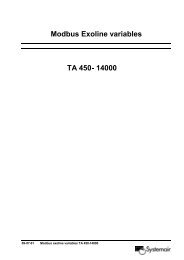
PART NAMES AND FUNCTIONS<br />
<strong>MSZ</strong>-<strong>FH25VE</strong> <strong>MSZ</strong>-FH35VE<br />
Air filter<br />
Air cleaning filter<br />
(Electrostatic anti-allergy<br />
enzyme filter and deodorizing filter)<br />
ACCESSORIES<br />
Horizontal<br />
vane<br />
Operation indicator lamp<br />
Model <strong>MSZ</strong>-<strong>FH25VE</strong> <strong>MSZ</strong>-FH35VE<br />
Installation plate 1<br />
Installation plate fi xing screw 4 × 25 mm 5<br />
Remote controller holder 1<br />
Fixing screw for 3.5 × 16 mm (Black) 2<br />
Battery (AAA) for remote controller 2<br />
Wireless remote controller 1<br />
Felt tape (For left or left-rear piping) 1<br />
Air cleaning fi lter<br />
(Electrostatic anti-allergy enzyme fi lter)<br />
1<br />
Air cleaning fi lter (Deodorizing fi lter) 1<br />
Air purifying device 1<br />
OBH623<br />
Front panel<br />
Air outlet<br />
(AIR PURIFYING)<br />
(POWER)<br />
4<br />
Air purifying device<br />
Air inlet<br />
i-see SENSOR<br />
Emergency<br />
operation<br />
switch<br />
Remote control receiving<br />
section<br />
Remote controller
3<br />
<strong>Electric</strong>al<br />
data<br />
Fan<br />
motor<br />
Special remarks<br />
Airfl ow<br />
Sound level<br />
Fan speed<br />
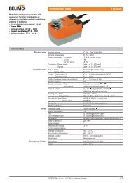
SPECIFICATION<br />
Indoor model <strong>MSZ</strong>-<strong>FH25VE</strong> <strong>MSZ</strong>-FH35VE<br />
Power supply Single phase 230 V, 50 Hz<br />
Power input<br />
1<br />
Cooling<br />
Heating<br />
W<br />
29<br />
29<br />
Running<br />
current 1<br />
Cooling<br />
Heating<br />
A<br />
0.28<br />
0.28<br />
Model RC0J30-MD<br />
Current 1<br />
Cooling<br />
Heating<br />
A<br />
0.28<br />
0.28<br />
Dimensions W × H × D mm 925 × 305(+17) × 234<br />
Weight kg 13.5<br />
Air direction 5<br />
Super High<br />
m3 696<br />
High 516<br />
Med. /h<br />
378<br />
Low 282<br />
Silent 234<br />
Super High<br />
m3 792<br />
High 552<br />
Med. /h<br />
384<br />
Low 282<br />
Silent 240<br />
Super High<br />
42<br />
High 36<br />
Med. dB(A)<br />
29<br />
Low 23 24<br />
Silent 20 21<br />
Super High<br />
44<br />
High 36<br />
Med. dB(A)<br />
29<br />
Low 24<br />
Silent 20 21<br />
Super High<br />
1,220<br />
High 970<br />
Med. rpm<br />
770<br />
Low 630<br />
Silent 550<br />
Super High<br />
1,350<br />
High 1,020<br />
Med. rpm<br />
780<br />
Low 630<br />
Silent 560<br />
Fan speed regulator 5<br />
Remote controller model SG13A<br />
NOTE: Test conditions are based on ISO 5151.<br />
Cooling: Indoor Dry-bulb temperature 27°C Wet-bulb temperature 19°C<br />
Outdoor Dry-bulb temperature 35°C<br />
Heating: Indoor Dry-bulb temperature 20°C<br />
Outdoor Dry-bulb temperature 7°C Wet-bulb temperature 6°C<br />
1 Measured under rated operating frequency.<br />
Cooling<br />
Heating<br />
Cooling<br />
Heating<br />
Cooling<br />
Heating<br />
Specifications and rating conditions of main electric parts<br />
Fuse (F11) T3.15AL250V<br />
Horizontal vane motor (MV1) 12 VDC<br />
Vertical vane motor (MV2) 12 VDC<br />
i-see SENSOR MOTOR (MT) 12 VDC<br />
Varistor (NR11) S10K300E2K1<br />
Terminal block (TB) 3P<br />
OBH623<br />
5
<strong>MSZ</strong>-<strong>FH25VE</strong> <strong>MSZ</strong>-FH35VE<br />
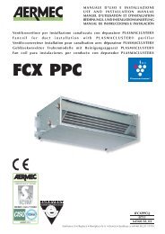
OCTAVE BAND SOUND PRESSURE LEVEL, dB re 0.0002 MICRO BAR<br />
4<br />
90<br />
80<br />
70<br />
60<br />
50<br />
40<br />
30<br />
20<br />
10<br />
NOISE CRITERIA CURVE<br />
FAN SPEED<br />
Super High<br />
FUNCTION SPL(dB(A)) LINE<br />
COOLING<br />
HEATING<br />
NC-10<br />
63 125 250 500 1000 2000 4000 8000<br />
BAND CENTER FREQUENCIES, Hz<br />
Test conditions<br />
Cooling: Dry-bulb temperature 27 °C<br />
Wet-bulb temperature 19 °C<br />
Heating: Dry-bulb temperature 20 °C<br />
OBH623<br />
42<br />
44<br />
NC-70<br />
NC-60<br />
NC-50<br />
NC-40<br />
NC-30<br />
NC-20<br />
0.8m<br />
INDOOR UNIT<br />
1m<br />
MICROPHONE<br />
6<br />
WALL
<strong>MSZ</strong>-<strong>FH25VE</strong> <strong>MSZ</strong>-FH35VE<br />
<strong>MSZ</strong>-<strong>FH25VE</strong> <strong>MSZ</strong>-FH35VE<br />
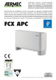
Piping<br />
5<br />
Insulation ø37 O.D<br />
Liquid line ø6.35 - 0.39 m (Flared connection ø6.35)<br />
Gas line ø9.52 - 0.34 m (Flared connection: ø9.52)<br />
Drain hose Insulation ø28 O.D Connected part ø16 O.D<br />
OBH623<br />
OUTLINES AND DIMENSIONS<br />
7<br />
Unit: mm
6<br />
WIRING DIAGRAM<br />
<strong>MSZ</strong>-<strong>FH25VE</strong> <strong>MSZ</strong>-FH35VE<br />
7<br />
REFRIGERANT SYSTEM DIAGRAM<br />
<strong>MSZ</strong>-<strong>FH25VE</strong> <strong>MSZ</strong>-FH35VE<br />
OBH623<br />
Indoor coil<br />
Indoor<br />
heat<br />
thermistor<br />
exchanger RT12 (main)<br />
Flared connection<br />
Indoor coil<br />
thermistor<br />
RT13 (sub)<br />
Room temperature<br />
thermistor<br />
RT11<br />
Refrigerant pipe ø9.52<br />
(with heat insulator)<br />
Flared connection<br />
Refrigerant pipe ø6.35<br />
(with heat insulator)<br />
Refrigerant flow in cooling<br />
Refrigerant flow in heating<br />
8<br />
Unit: mm
8<br />
SERVICE FUNCTIONS<br />
<strong>MSZ</strong>-<strong>FH25VE</strong> <strong>MSZ</strong>-FH35VE<br />
8-1. TIMER SHORT MODE<br />
For service, the following set time can be shortened by short circuit of JPG and JPS on the electronic control P.C. board.<br />
(Refer to 10-7.)<br />
Set time: 3 minutes → 3 seconds (It takes 3 minutes for the compressor to start operation. However, the starting time is<br />
shortened by short circuit-of JPG and JPS.)<br />
8-2. HOW TO SET REMOTE CONTROLLER EXCLUSIVELY FOR A PARTICULAR INDOOR UNIT<br />
A maximum of 4 indoor units with wireless remote controllers can be used in a room.<br />
To operate the indoor units individually with each remote controller, assign a number to each remote controller according<br />
to the number of the indoor unit.<br />
This setting can be set only when all the following conditions are met:<br />
• The remote controller is powered OFF.<br />
• Weekly timer is not set.<br />
• Weekly timer is not being edited.<br />
(1) Hold down button on the remote controller for 2 seconds to enter the p<strong>air</strong>ing mode.<br />
(2) Press button again and assign a number to each remote controller.<br />
Each press of button advances the number in the following order: 1 → 2 → 3 → 4.<br />
(3) Press button to complete the p<strong>air</strong>ing setting.<br />
After you turn the breaker ON, the remote controller that first sends a signal to an indoor unit will be regarded as the<br />
remote controller for the indoor unit.<br />
Once they are set, the indoor unit will only receive the signal from the assigned remote controller afterwards.<br />
8-3. SETTING THE INSTALLATION POSITION<br />
Be sure to set the remote controller according to the installed position of the indoor unit.<br />
Installation position:<br />
Left: Distance to objects (wall, cabinet, etc.) is less than 50 cm to the left<br />
Center: Distance to objects (wall, cabinet, etc.) is more than 50 cm to the left and right<br />
Right: Distance to objects (wall, cabinet, etc.) is less than 50 cm to the right<br />
The installation position can be set only when all the following conditions are met:<br />
• The remote controller is powered OFF.<br />
• Weekly timer is not set.<br />
• Weekly timer is not being edited.<br />
(1) Hold down button on the remote controller for 2 seconds to enter the position setting mode.<br />
(2) Select the target installation position by pressing button. (Each press of the button displays the<br />
positions in order: center → right → left.)<br />
(3) Press button to complete the position setting.<br />
Installation position<br />
Remote controller<br />
display<br />
Left Center Right<br />
OBH623<br />
9<br />
(Left) (Center)(Right)
8-4. AUTO RESTART FUNCTION<br />
When the indoor unit is controlled with the remote controller, the operation mode, the set temperature, and the fan speed<br />
are memorized by the indoor electronic control P.C. board. “AUTO RESTART FUNCTION” automatically starts operation<br />
in the same mode just before the shutoff of the main power.<br />
Operation<br />
If the main power has been cut, the operation settings remain.<br />
After the power is restored, the unit restarts automatically according to the memory.<br />
(However, it takes at least 3 minutes for the compressor to start running.)<br />
How to disable “AUTO RESTART FUNCTION”<br />
Turn off the main power for the unit.<br />
Cut the jumper wire to JR77 on the indoor electronic control P.C. board. (Refer to 10-7.)<br />
NOTE:<br />
• The operation settings are memorized when 10 seconds have passed after the indoor unit was operated with the remote<br />
controller.<br />
• If main power is turned OFF or a power failure occurs while AUTO START/STOP timer is active, the timer setting is cancelled.<br />
• If the unit has been off with the remote controller before power failure, the auto restart function does not work as the<br />
power button of the remote controller is OFF.<br />
• To prevent breaker OFF due to the rush of starting current, systematize other home appliance not to turn ON at the same<br />
time.<br />
• When some <strong>air</strong> <strong>conditioners</strong> are connected to the same supply system, if they are operated before power failure, the<br />
starting current of all the compressors may flow simultaneously at restart.<br />
Therefore, the special counter-measures are required to prevent the main voltage-drop or the rush of the starting current<br />
by adding to the system that allows the units to start one by one.<br />
OBH623<br />
Indoor electronic control<br />
P.C. board<br />
CN110<br />
CN151<br />
JR77<br />
10<br />
BZ
9<br />
MICROPROCESSOR CONTROL<br />
<strong>MSZ</strong>-<strong>FH25VE</strong> <strong>MSZ</strong>-FH35VE<br />
WIRELESS REMOTE CONTROLLER<br />
Operation display section<br />
Temperature buttons<br />
Signal transmitting section<br />
Distance of signal :<br />
About 6 m<br />
Beep(s) is (are) heard from<br />
the indoor unit when the<br />
signal is received.<br />
OPERATION SELECT button<br />
ECONO COOL button<br />
POWERFUL button<br />
i-save button<br />
NATURAL FLOW button<br />
OPERATE/STOP<br />
(ON/OFF) button<br />
SENSOR (i-see) button<br />
Indication of<br />
remote controller<br />
model is on back<br />
NOTE: Last setting will be stored after the unit is turned OFF with the remote controller. Indoor unit receive the signal of the<br />
remote controller with beeps.<br />
INDOOR UNIT DISPLAY SECTION<br />
Operation Indicator lamp<br />
The operation indicator at the right side of the indoor unit indicates the operation state.<br />
•The following indication applies regardless of shape of the indication.<br />
Indication Operation state Room temperature<br />
Lighted<br />
Standby mode<br />
Blinking<br />
(Only during multi system -<br />
operation)<br />
Not lighted<br />
11<br />
FAN SPEED CONTROL button<br />
WIDE VANE button<br />
VANE CONTROL button<br />
PURIFIER button<br />
INDIRECT/DIRECT button<br />
TIME, TIMER set buttons<br />
FORWARD button<br />
BACKWARD button<br />
WEEKLY TIMER<br />
set buttons<br />
RESET button<br />
CLOCK button<br />
Lid<br />
Slide the lid down<br />
to open the remote<br />
controller. Slide it down<br />
further to get to the<br />
weekly timer buttons.<br />
9-1. COOL ( ) OPERATION<br />
(1) Press OPERATE/STOP (ON/OFF) button.<br />
OPERATION INDICATOR lamp of the indoor unit turns on with a beep tone.<br />
(2) Select COOL mode with OPERATION SELECT button.<br />
(3) Press TEMPERATURE buttons TEMP or button to select the desired temperature. The setting range is 16 - 31°C.<br />
1. Coil frost prevention<br />
The compressor operational frequency is controlled by the temperature of the indoor heat exchanger to prevent the coil<br />
from frosting.<br />
When the temperature of indoor heat exchanger becomes too low, the coil frost prevention mode works.<br />
The indoor fan operates at the set speed and the compressor stops. This mode continues until the temperature of indoor<br />
heat exchanger rises.<br />
2. Low outside temperature operation<br />
When the outside temperature is lower, low outside temperature operation starts, and the outdoor fan slows or stops.<br />
3. Indoor fan speed control<br />
When the thermostat turns OFF, the indoor fan operates very Low to reduce power consumption.<br />
When the room temperature rises and the thermostat is ON, the indoor fan operates according to the settings on the<br />
remote controller.<br />
OBH623
9-2. DRY ( ) OPERATION<br />
(1) Press OPERATE/STOP (ON/OFF) button.<br />
OPERATION INDICATOR lamp of the indoor unit turns on with a beep tone.<br />
(2) Select DRY mode with OPERATION SELECT button.<br />
(3) The set temperature is determined from the initial room temperature.<br />
1. Coil frost prevention<br />
Coil frost prevention is as same as COOL mode. (9-1.1.)<br />
2. Low outside temperature operation<br />
Low outside temperature operation is as same as COOL mode. (9-1.2.)<br />
3. Indoor fan speed control<br />
Indoor fan speed control is as same as COOL mode. (9-1.3.)<br />
9-3. FAN ( ) OPERATION<br />
(1) OPERATION INDICATOR lamp of the indoor unit turns on with a beep tone.<br />
(2) Select FAN mode with OPERATION SELECT button.<br />
(3) Select the desired fan speed. When AUTO, it becomes Low.<br />
Only indoor fan operates.<br />
Outdoor unit does not operate.<br />
9-4. HEAT ( ) OPERATION<br />
(1) Press OPERATE/STOP (ON/OFF) button.<br />
OPERATION INDICATOR lamp of the indoor unit turns on with a beep tone.<br />
(2) Select HEAT mode with OPERATION SELECT button.<br />
(3) Press TEMPERATURE buttons TEMP or button to select the desired temperature. The setting range is 16 - 31°C.<br />
1. Cold <strong>air</strong> prevention control<br />
When the compressor is not operating or is starting, and the temperature of indoor heat exchanger and/or the room temperature<br />
is low or when defrosting is being done, the indoor fan will stop or rotate in Very Low speed.<br />
2. High pressure protection<br />
The compressor operational frequency is controlled by the temperature of the indoor heat exchanger to prevent the condensing<br />
pressure from increasing excessively.<br />
When the temperature of indoor heat exchanger becomes too high, the high pressure protection works.<br />
The indoor fan operates following the cold <strong>air</strong> prevention control. This mode continues until the temperature of indoor<br />
heat exchanger falls.<br />
3. Defrosting<br />
Defrosting starts when the temperature of outdoor heat exchanger becomes too low.<br />
The compressor stops once, the indoor/outdoor fans stop, the 4-way valve reverses, and the compressor re-starts.<br />
This mode continues until the temperature of outdoor heat exchanger rises or the fixed time passes.<br />
9-5. AUTO CHANGE OVER ··· AUTO MODE OPERATION<br />
Once desired temperature is set, unit operation is switched automatically between COOL and HEAT operation.<br />
Mode selection<br />
(1) Initial mode<br />
When unit starts the operation with AUTO operation from OFF:<br />
• If the room temperature is higher than the set temperature, operation starts in COOL mode.<br />
• If the room temperature is equal to or lower than the set temperature, operation starts in HEAT mode.<br />
(2) Mode change<br />
COOL mode changes to HEAT mode when about 15 minutes have passed with the room temperature 1°C below the<br />
set temperature.<br />
HEAT mode changes to COOL mode when about 15 minutes have passed with the room temperature 1°C above the<br />
set temperature.<br />
NOTE 1<br />
If two or more indoor units are operating in multi system, there might be a case that the indoor unit, which is operating in<br />
(AUTO), cannot change over to the other operating mode (COOL ↔ HEAT) and becomes a state of standby.<br />
Refer to NOTE 2 “FOR MULTI SYSTEM AIR CONDITIONER”.<br />
OBH623<br />
12
NOTE 2<br />
FOR MULTI SYSTEM AIR CONDITIONER<br />
OUTDOOR UNIT: MXZ series<br />
Multi system <strong>air</strong> conditioner can connect two or more indoor units with one outdoor unit.<br />
• When you try to operate two or more indoor units with one outdoor unit simultaneously, one for the cooling and<br />
the others for heating, the operation mode of the indoor unit that operates first is selected. Other indoor units<br />
cannot operate, and operation indicator lamp flashes as shown in the figure below. In this case, please set all the<br />
indoor units to the same operation mode.<br />
OPERATION INDICATOR<br />
• When indoor unit starts the operation while the defrosting of outdoor unit is being done, it takes a few minutes (max.<br />
10 minutes) to blow out the warm <strong>air</strong>.<br />
• In the heating operation, though indoor unit that does not operate may get warm or the sound of refrigerant flowing<br />
may be heard, they are not malfunction. The reason is that the refrigerant continuously flows into it.<br />
9-6. AUTO VANE OPERATION<br />
1. Horizontal vane<br />
(1) Vane motor drive<br />
These models are equipped with a stepping motors for the horizontal vanes. The rotating direction, speed, and angle<br />
of the motor are controlled by pulse signals (approximately 12 V) transmitted from indoor microprocessor.<br />
13<br />
Lighted<br />
Blinking<br />
Not lighted<br />
(2) The horizontal vane angle and mode change as follows by pressing VANE CONTROL ( ) button.<br />
Horizontal<br />
position<br />
AUTO 1 2 3 4 5 SWING<br />
NOTE: The right and left horizontal vanes set to the same level may not align perfectly.<br />
(3) Positioning<br />
To confirm the standard position, the vane move until it touches the vane stopper. Then the vane is set to the selected<br />
angle.<br />
Confirming of standard position is performed in the following cases:<br />
(a) When the operation starts or finishes (including timer operation).<br />
(b) When the test run starts.<br />
(c) When standby mode (only during multi system operation) starts or finishes.<br />
(4) VANE AUTO ( ) mode<br />
In VANE AUTO mode, the microprocessor automatically determines the vane angle to make the optimum room temperature<br />
distribution.<br />
In COOL and DRY operation<br />
Vane angle is fixed to Horizontal position.<br />
In HEAT operation<br />
Vane angle is fixed to Angle 4.<br />
(5) STOP (operation OFF) and ON TIMER standby<br />
In the following cases, the horizontal vane returns to the closed position.<br />
(a) When OPERATE/STOP (ON/OFF) button is pressed (POWER OFF).<br />
(b) When the operation is stopped by the emergency operation.<br />
(c) When ON TIMER is ON standby.<br />
(6) Dew prevention<br />
During COOL or DRY operation with the vane angle at Angle 4 or 5 when the compressor cumulative operation time<br />
exceeds 1 hour, the vane angle automatically changes to Angle 3 for dew prevention.<br />
OBH623<br />
4
(7) SWING ( ) mode<br />
By selecting SWING mode with VANE CONTROL button, the horizontal vanes swing vertically.<br />
When COOL, DRY or FAN mode is selected, only the upper vane swings.<br />
(8) Cold <strong>air</strong> prevention in HEAT operation<br />
The horizontal vane position is set to Upward.<br />
NOTE: When 2 or more indoor units are operated with multi outdoor unit, even if any indoor unit turns thermostat off,<br />
this control does not work in the indoor unit.<br />
(9) ECONO COOL ( ) operation (ECONOmical operation)<br />
When ECONO COOL button is pressed in COOL mode, set temperature is automatically set 2°C higher.<br />
Also the horizontal vane swings in various cycle.<br />
SWING operation makes you feel cooler than set temperature. So, even though the set temperature is higher, the <strong>air</strong><br />
conditioner can keep comfort. As a result, energy can be saved.<br />
To cancel this operation, select a different mode or press one of the following buttons in ECONO COOL operation:<br />
ECONO COOL, VANE CONTROL, POWERFUL or NATURAL FLOW button.<br />
(10) POWERFUL ( ) operation<br />
The <strong>air</strong> conditioner automatically adjusts the fan speed and the set temperature, and operates the POWERFUL mode.<br />
The POWERFUL mode is cancelled automatically 15 minutes after operation starts, or when POWERFUL button<br />
is pressed once again within 15 minutes after operation starts. The operation mode returns to the mode prior to<br />
POWERFUL operation. POWERFUL mode also is cancelled, when the OPERATE/STOP (ON/OFF), ECONO COOL,<br />
FAN SPEED CONTROL, NATURAL FLOW or i-save button is pressed within 15 minutes after operation starts, or operation<br />
mode is changed.<br />
2. Vertical vane<br />
(1) Vane motor drive<br />
These models are equipped with a stepping motor for the vertical vane. The rotating direction, speed, and angle of<br />
the motor are controlled by pulse signals (approximately 12 V) transmitted from microprocessor.<br />
(2) The vertical vane angle and mode change as follows by pressing WIDE VANE CONTROL button.<br />
(3) Positioning<br />
1 2 3 4 5<br />
To confirm the standard position, the vane moves until it touches the vane stopper. Then the vane is set to the selected<br />
angle.<br />
Confirming of standard position is performed in the following cases:<br />
(a) OPERATE/STOP (ON/OFF) button is pressed (POWER ON).<br />
14<br />
(SWING)<br />
(4) SWING ( ) MODE<br />
By selecting SWING mode with WIDE VANE CONTROL button, the vertical vane swings horizontally. The remote<br />
controller displays “ ”. Swing mode is cancelled when WIDE MODE CONTROL button is pressed once again.<br />
OBH623
9-7. TIMER OPERATION<br />
1. How to set the time<br />
(1) Check that the current time is set correctly.<br />
NOTE: Timer operation will not work without setting the current time. Initially “0:00” blinks at the current time display<br />
of TIME MONITOR, so set the current time correctly with CLOCK button.<br />
How to set the current time<br />
(a) Press the CLOCK button.<br />
(b) Press the TIME SET buttons ( and ) to set the current time.<br />
• Each time FORWARD button ( ) is pressed, the set time increases by 1 minute, and each time BACKWARD<br />
button ( ) is pressed, the set time decreases by 1 minute.<br />
• Pressing those buttons longer, the set time increases/decreases by 10 minutes.<br />
(c) Press the CLOCK set button.<br />
(2) Press OPERATE/STOP (ON/OFF) button to start the <strong>air</strong> conditioner.<br />
(3) Set the time of timer.<br />
ON timer setting<br />
(a) Press ON TIMER button( ) during operation.<br />
(b) Set the time of the timer using TIME SET buttons ( and ).<br />
OFF timer setting<br />
(a) Press OFF TIMER button ( ) during operation.<br />
(b) Set the time of the timer using TIME SET buttons ( and ).<br />
Each time FORWARD button ( ) is pressed, the set time increases by 10 minutes: each time BACKWARD button<br />
( ) is pressed, the set time decreases by 10 minutes.<br />
2. To release the timer<br />
To release ON timer, press ON TIMER button ( ).<br />
To release OFF timer, press OFF TIMER button( ).<br />
TIMER is cancelled and the display of set time disappears.<br />
PROGRAM TIMER<br />
• OFF timer and ON timer can be used in combination. The timer of the set time that is reached first will operate first.<br />
• “ ” and “ ” display shows the order of OFF timer and ON timer operation.<br />
(Example 1) The current time is 8:00 PM.<br />
The unit turns off at 11:00 PM, and on at 6:00 AM.<br />
15<br />
(Example 2) The current time is 11:00 AM.<br />
The unit turns on at 5:00 PM, and off at 9:00 PM.<br />
NOTE: If the main power is turned OFF or a power failure occurs while ON/OFF timer is active, the timer setting is cancelled.<br />
As these models are equipped with an auto restart function, the <strong>air</strong> conditioner starts operating with timer<br />
cancelled when power is restored.<br />
OBH623
9-8. WEEKLY TIMER OPERATION<br />
• A maximum of 4 ON or OFF timers can be set for individual days of the week.<br />
• A maximum of 28 ON or OFF timers can be set for a week.<br />
NOTE:<br />
The simple ON/OFF timer setting is available while the weekly timer is on. In this case, the ON/OFF timer has priority over the weekly<br />
timer; the weekly timer operation will start again after the simple ON/OFF timer is complete.<br />
1. How to set the weekly timer<br />
* Make sure that the current time and day are set correctly.<br />
(1) Press button to enter the weekly timer setting mode.<br />
(2) Press and buttons to select setting day and number.<br />
Pressing selects the day of<br />
the week to be set.<br />
* All days can be selected.<br />
(3) Press , , and buttons to set ON/OFF, time, and temperature.<br />
Pressing<br />
selects ON/OFF timer.<br />
Pressing<br />
deletes timer setting.<br />
Pressing<br />
adjusts the time.<br />
* Hold down the button to change the time quickly.<br />
* blinks.<br />
E.g. : [Mon Tue ... Sun]<br />
and [1] are selected.<br />
Pressing selects<br />
the setting number.<br />
E.g. : [ON], [6:00]<br />
and [24°C] are<br />
selected.<br />
Pressing<br />
adjusts the temperature.<br />
Press and buttons to continue setting the timer for other days and/or numbers.<br />
(4) Press button to complete and transmit the weekly timer setting.<br />
NOTE:<br />
* which was blinking<br />
goes out, and the<br />
current time will be<br />
displayed.<br />
• Press button to transmit the setting information of weekly timer to the indoor unit. Point the remote controller toward the<br />
indoor unit for 3 seconds.<br />
• When setting the timer for more than one day of the week or one number, button does not have to be pressed per each<br />
setting. Press button once after all the settings are complete. All the weekly timer settings will be saved.<br />
• Press button to enter the weekly timer setting mode, and press and hold button for 5 seconds to erase all weekly<br />
timer settings. Point the remote controller toward the indoor unit.<br />
OBH623<br />
16
(5) Press button to turn the weekly timer ON. ( lights.)<br />
•When the weekly timer is ON, the day of the week whose timer setting is complete, will light.<br />
Press button again to turn the weekly timer OFF. ( goes out.)<br />
NOTE:<br />
The saved settings will not be cleared when the weekly timer is turned OFF.<br />
2. Checking weekly timer setting<br />
(1) Press button to enter the weekly timer setting mode.<br />
* blinks.<br />
(2) Press or buttons to view the setting of the particular day or number.<br />
(3) Press<br />
NOTE:<br />
button to exit the weekly timer setting.<br />
When all days of the week are selected to view the settings and a different setting is included among them,<br />
displayed.<br />
will be<br />
9-9. i-see CONTROL ( ) MODE<br />
In the i-see control mode, the room temperature is controlled based on the sensible temperature.<br />
(1) Press SENSOR button with a thin instrument during COOL, DRY, HEAT and AUTO mode to activate i-see control mode (<br />
The default setting is “active”.<br />
).<br />
(2) Press SENSOR button again to activate ABSENCE DETECTION (<br />
(3) Press SENSOR button again to release i-see control mode.<br />
).<br />
ABSENCE DETECTION ( )<br />
This function automatically changes the operation to energy-saving operation when nobody is in the room.<br />
(1) To activate this function, press SENSOR button until<br />
i-see control mode.<br />
appears on the operation display of the remote controller during the<br />
(2) Press SENSOR button again to release ABSENCE DETECTION.<br />
9-10. INDIRECT/DIRECT mode<br />
The INDIRECT/DIRECT mode offers fi nely-tuned operation by locating where an occupant is in the room.<br />
(1) Press INDIRECT/DIRECT button during COOL, DRY, HEAT or AUTO mode to activate INDIRECT/DIRECT mode.<br />
This mode is only available when the i-see control mode is effective.<br />
(2) Each press of INDIRECT/DIRECT button changes INDIRECT/DIRECT in the following order:<br />
(INDIRECT) (DIRECT) (OFF)<br />
(INDIRECT): An occupant will be less exposed to direct <strong>air</strong>flow.<br />
(DIRECT) : Mainly the vicinity of an occupant will be <strong>air</strong>-conditioned.<br />
NOTE:<br />
• Horizontal and vertical <strong>air</strong>fl ow directions will be automatically selected.<br />
• If you still feel uncomfortable with the <strong>air</strong> direction determined by the INDIRECT mode, adjust the <strong>air</strong> direction manually.<br />
• Cancelling the i-see control mode automatically cancels the INDIRECT/DIRECT mode.<br />
INDIRECT/DIRECT mode is also cancelled when the VANE or WIDE VANE buttons is pressed.<br />
• Do not touch the i-see SENSOR. This may cause malfunction of the i-see SENSOR.<br />
9-11. NATURAL FLOW ( ) OPERATION<br />
In NATURAL FLOW operation, <strong>air</strong> fl ow will become more like natural wind. An occupant will not be directly exposed to the<br />
<strong>air</strong> fl ow and feel more comfortable.<br />
(1) Press NATURAL FLOW button during COOL or FAN mode to start NATURAL FLOW operation.<br />
(2) Press NATURAL FLOW button again to cancel NATURAL FLOW operation.<br />
• NATURAL FLOW operation is also cancelled when the POWERFUL or ECONO COOL button is pressed.<br />
NOTE: As the fan speed changes constantly during NATURAL FLOW operation, the sound of <strong>air</strong> fl ow, wind velocity and <strong>air</strong> fl ow<br />
temperature also change. This is not a malfunction.<br />
OBH623<br />
17
9-12. AIR PURIFYING ( ) OPERATION<br />
In the AIR PURIFYING operation, the indoor unit built-in device reduces <strong>air</strong>borne fungi, viruses, mold, and allergens.<br />
(1) Press PURIFIER button to start AIR PURIFYING operation.<br />
• AIR PURIFYING lamp turns on. (Display section)<br />
(2) Press PURIFIER button again to cancel AIR PURIFYING operation.<br />
• AIR PURIFYING lamp turns off. (Display section)<br />
NOTE:<br />
• Never touch the <strong>air</strong> purifying device during operation. Although the <strong>air</strong> purifying device is safety-conscious design, touching this<br />
device could be the cause of trouble as this device discharge high voltage electricity.<br />
• A “hissing” sound may be heard during the <strong>air</strong> purifying operation. This sound is produced when plasma is being discharged.<br />
This is not a malfunction.<br />
• AIR PURIFYING lamp does not turn on if the front panel is not closed completely.<br />
9-13. i-save ( ) OPERATION<br />
1. How to set i-save operation<br />
(1) Press OPERATE/STOP (ON/OFF) button.<br />
(2) Select COOL, HEAT or ECONO COOL mode.<br />
(3) Press i-save button.<br />
(4) Set the temperature, fan speed, and <strong>air</strong>fl ow direction for i-save operation.<br />
NOTE:<br />
• i-save operation cannot be selected during DRY or AUTO mode operation.<br />
• The setting range of HEAT mode i-save operation is 10°C and 16 - 31°C.<br />
• 2 groups of setting can be saved. (One for COOL/ECONO COOL, one for HEAT)<br />
2. How to cancel operation<br />
• Press i-save button again.<br />
• i-save operation can also be cancelled by pressing POWERFUL button or OPERATION SELECT button to change the<br />
operation mode.<br />
The same setting is select from the next time by simply pressing i-save button.<br />
9-14. EMERGENCY/TEST OPERATION<br />
In case of test run operation or emergency operation, use<br />
EMERGENCY OPERATION switch on the right side of the indoor unit.<br />
Emergency operation is available when the remote controller is missing,<br />
has failed or the batteries of the remote controller run down. The<br />
unit will start and OPERATION INDICATOR lamp will light.<br />
The first 30 minutes of operation is the test run operation. This operation<br />
is for servicing. The indoor fan runs at High speed and the temperature<br />
control does not work.<br />
After 30 minutes of test run operation, the system shifts to<br />
EMERGENCY COOL/HEAT MODE with a set temperature of 24°C.<br />
The fan speed shifts to Med.<br />
The coil frost prevention works even in the test run or the emergency<br />
operation.<br />
In the test run or emergency operation, the horizontal vane operates<br />
in VANE AUTO ( ) mode.<br />
Emergency operation continues until EMERGENCY OPERATION<br />
switch is pressed once or twice or the unit receive any signal from the<br />
remote controller. In case of latter, normal operation will start.<br />
NOTE: Do not press EMERGENCY OPERATION switch during normal<br />
operation.<br />
Emergency<br />
operation switch<br />
(E.O. SW)<br />
18<br />
Operation mode COOL/HEAT<br />
Set temperature 24°C<br />
Fan speed Med.<br />
Horizontal vane Auto<br />
The operation mode is indicated by the Operation<br />
Indicator lamp as following<br />
Operation Indicator lamp<br />
EMERGENCY COOL<br />
↓<br />
EMERGENCY HEAT<br />
↓<br />
STOP<br />
Lighted<br />
Not lighted<br />
9-15. 3-MINUTE TIME DELAY OPERATION<br />
When the system turns OFF, compressor will not restart for 3 minutes as 3-minute time delay function operates to protect<br />
compressor from overload.<br />
OBH623
10<br />
TROUBLESHOOTING<br />
<strong>MSZ</strong>-<strong>FH25VE</strong> <strong>MSZ</strong>-FH35VE<br />
10-1. CAUTIONS ON TROUBLESHOOTING<br />
1. Before troubleshooting, check the following<br />
1) Check the power supply voltage.<br />
2) Check the indoor/outdoor connecting wire for miswiring.<br />
2. Take care of the following during servicing<br />
1) Before servicing the <strong>air</strong> conditioner, be sure to turn OFF the main unit first with the remote controller, and then after<br />
confirming the horizontal vane is closed, turn OFF the breaker and/or disconnect the power plug.<br />
2) Be sure to turn OFF the power supply before removing the front panel, the cabinet, the top panel, and the P.C. board.<br />
3) When removing the P.C. board, hold the edge of the board with care NOT to apply stress on the components.<br />
4) When connecting or disconnecting the connectors, hold the housing of the connector. DO NOT pull the lead wires.<br />
<br />
Lead wiring Housing point<br />
3. Troubleshooting procedure<br />
1) First, check if the OPERATION INDICATOR lamp on the indoor unit is flashing ON and OFF to indicate an abnormality.<br />
To make sure, check how many times the OPERATION INDICATOR lamp is flashing ON and OFF before starting service<br />
work.<br />
2) Before servicing, check that the connector and terminal are connected properly.<br />
3) When the electronic control P.C. board seems to be defective, check the copper foil pattern for disconnection and the<br />
components for bursting and discoloration.<br />
4) When troubleshooting, Refer to 10-2, 10-3 and 10-4.<br />
4. How to replace batteries<br />
Weak batteries may cause the remote controller malfunction.<br />
In this case, replace the batteries to operate the remote controller normally.<br />
Remove the front lid and insert batteries.<br />
Then reattach the front lid.<br />
NOTE: 1. If RESET button is not pressed, the remote controller may not operate correctly.<br />
2. This remote controller has a circuit to automatically reset the microcomputer when batteries are replaced.<br />
This function is equipped to prevent the microcomputer from malfunctioning due to the voltage drop caused by the<br />
battery replacement.<br />
3. Do not use the leaking batteries.<br />
OBH623<br />
Insert the negative pole of the<br />
batteries first. Check if the polarity<br />
of the batteries is correct.<br />
19<br />
Press RESET button with a thin instrument, and<br />
then use the remote controller.<br />
RESET button
10-2. FAILURE MODE RECALL FUNCTION<br />
Outline of the function<br />
This <strong>air</strong> conditioner can memorize the abnormal condition which has occurred once.<br />
Even though LED indication listed on the troubleshooting check table (10-4.) disappears, the memorized failure details<br />
can be recalled.<br />
1. Flow chart of failure mode recall function for the indoor/outdoor unit<br />
Operational procedure<br />
The cause of abnormality cannot be found because the abnormality does not recur.<br />
Setting up the failure mode recall function<br />
Turn ON the power supply.<br />
<br />
While pressing both OPERATION SELECT button and TEMP button on the remote<br />
controller at the same time, press RESET button.<br />
First, release RESET button.<br />
Hold down the other two buttons for another 3 seconds. Confi rm that the indicators<br />
on the LCD screen shown in the right fi gure are all displayed. Then release the buttons.<br />
Judgment of indoor/outdoor abnormality<br />
Does POWER lamp on the indoor unit blink at the<br />
interval of 0.5 seconds?<br />
Blinks: Either indoor or outdoor unit is abnormal.<br />
Beep is emitted at the same timing as the<br />
blinking of the left lamp of OPERATION<br />
INDICATOR lamp. 2<br />
Yes<br />
(Blinks)<br />
Before blinking, does POWER lamp stay ON<br />
for 3 seconds?<br />
Stays ON for 3 seconds (without beep):<br />
The outdoor unit is abnormal.<br />
No<br />
The indoor unit is abnormal.<br />
Check the blinking pattern, and confi rm the abnormal point with the indoor unit<br />
failure mode table. (Refer to 10-2.2)<br />
Make sure to check at least two consecutive blinking cycles. 2<br />
Releasing the failure mode recall function<br />
Release the failure mode recall function by the following procedures.<br />
Turn OFF the power supply and turn it ON again.<br />
Press RESET button of the remote controller.<br />
Rep<strong>air</strong> the defective parts.<br />
Deleting the memorized abnormal condition<br />
After rep<strong>air</strong>ing the unit, recall the failure mode again according to "Setting up the failure mode recall<br />
function" mentioned above.<br />
Press OPERATE/STOP (ON/OFF) button of the remote controller (the set temperature is displayed)<br />
with the remote controller headed towards the indoor unit.<br />
Press EMERGENCY OPERATION switch so that the memorized abnormal condition is deleted. 4<br />
Release the failure mode recall function according to "Releasing the failure mode recall function"<br />
mentioned above.<br />
Yes<br />
No<br />
(OFF)<br />
NOTE: 1. Make sure to release the failure mode recall function once it is set up, otherwise the unit cannot operate properly.<br />
2. If the abnormal condition is not deleted from the memory, the last abnormal condition is kept memorized.<br />
2. Blinking pattern when the indoor unit is abnormal:<br />
ON<br />
OFF<br />
Press OPERATE/STOP (ON/OFF) button of the remote controller (the set temperature is<br />
displayed) with the remote controller headed towards the indoor unit. 1<br />
2.5-second OFF<br />
Blinking at 0.5second<br />
interval<br />
2.5-second OFF<br />
Beeps<br />
Beeps<br />
Repeated cycle Repeated cycle<br />
3.Blinking pattern when the outdoor unit is abnormal:<br />
Blinking at 0.5-<br />
2.5-second OFF 3-second ON second interval<br />
ON<br />
OFF<br />
No beep<br />
Repeated cycle<br />
Beeps<br />
OBH623<br />
1 Regardless of normal or abnormal condition,<br />
a short beep is emitted once the signal is<br />
received.<br />
Blinking at 0.5second<br />
interval<br />
20<br />
Indoor unit is normal.<br />
But the outdoor unit might be abnormal because there are some abnormalities<br />
that cannot be recalled with this way.<br />
Confi rm if outdoor unit is abnormal according to the detailed outdoor unit<br />
failure mode recall function.<br />
The outdoor unit is abnormal.<br />
Check the blinking pattern, and confi rm the abnormal point with the<br />
outdoor unit failure mode table. (Refer to outdoor unit service manual.)<br />
Make sure to check at least two consecutive blinking cycles. 3<br />
Beeps<br />
Repeated cycle<br />
2.5-second OFF 3-second ON<br />
NOTE: It takes up to 1 minute to indicate the outdoor unit abnormality.<br />
Even if the OPERATION INDICATOR lamp is not lighting, keep<br />
checking at least 1 minute or longer.<br />
Blinking at 0.5second<br />
interval<br />
No beep Beeps<br />
Repeated cycle<br />
4 The information regarding whether the connected<br />
outdoor unit is a low-standby-power model or a nonlow-standby-power<br />
model will also be initialized.<br />
(Default= compatible with a low-standby-power model)<br />
Repeated cycle
2. Flow chart of AIR PURIFYING power failure mode recall function<br />
Operational procedure<br />
With the remote controller headed towards the indoor unit, press TOO COOL or TOO<br />
WARM button to adjust the set temperature to 23 °C. 1<br />
Does POWER lamp on the indoor<br />
unit blink at the interval of 0.5 seconds?<br />
Blinks: The <strong>air</strong> purifying device is abnormal.<br />
Beep is emitted at the same timing as the<br />
blinking of POWER lamp. 2<br />
Yes<br />
(Blinks)<br />
The <strong>air</strong> purifying device is abnormal.<br />
Check the blinking pattern, and refer to confirm the<br />
abnormal point with the AIR PURIFYING power failure mode table<br />
(10-2.5.).<br />
Make sure to check at least two consecutive blinking cycles. 2<br />
Releasing the failure mode recall function<br />
Release the failure mode recall function by the following procedures.<br />
Turn OFF the power supply and turn it ON again.<br />
Press RESET button of the remote controller.<br />
Deleting the memorized abnormal condition<br />
Rep<strong>air</strong> the defective parts.<br />
Note1. Make sure to release the failure mode recall function once it is set up, otherwise the unit cannot operate properly.<br />
2. If the abnormal condition is not deleted from the memory, the last abnormal condition is kept memorized.<br />
2.Blinking pattern when the <strong>air</strong> purifying device is abnormal:<br />
ON<br />
OFF<br />
The <strong>air</strong> purifying device might be abnormal.<br />
Confirm if the <strong>air</strong> purifying device is abnormal according to the following procedures.<br />
Confirm that the remote controller is in the failure mode recall<br />
function.<br />
2.5-second OFF<br />
Blinking at 0.5second<br />
interval<br />
2.5-second OFF<br />
Beeps<br />
Beeps<br />
Repeated cycle Repeated cycle<br />
21<br />
No<br />
(OFF)<br />
Blinking at 0.5second<br />
interval<br />
1. Regardless of normal or abnormal condition, a short<br />
beep is emitted as the signal is received.<br />
The <strong>air</strong> purifying device is normal.<br />
After rep<strong>air</strong>ing the unit, recall the failure mode again according to<br />
"Setting up the failure mode recall function" mentioned above.<br />
Press OPERATE/STOP(ON/OFF) button of the remote controller (the set temperature is displayed)<br />
with the remote controller headed towards the indoor unit.<br />
Press EMERGENCY OPERATION switch so that the memorized abnormal condition is deleted.<br />
Release the failure mode recall function according to "Releasing the failure mode recall function"<br />
mentioned above.<br />
Release the failure mode recall function according to the left<br />
mentioned procedure.<br />
Beeps<br />
Repeated cycle<br />
3. AIR PURIFYING power operation check<br />
AIR PURIFYING power goes ON when PURIFIER button on the remote contoller is pressed<br />
with any set temperature displayed during failure mode recall function.<br />
Check the operation display section of the remote controller to confirm that AIR PURIFYING power is activated.<br />
While AIR PURIFYING lamp stays OFF, it means normal.<br />
Flashing AIR PURIFYING lamp means abnormal, the AIR PURIFYING power is not conducted.<br />
AIR PURIFYING lamp<br />
Continuously blinking<br />
2-time flash<br />
Remedy<br />
Follow "Check of AIR PURIFYING power" to identify the error. (Refer to 10-6. .)<br />
AIR PURIFYING power control circuit on the indoor electronic control P.C. board is out of order.<br />
(Refer to 10-6. .)<br />
NOTE: Perform the above mentioned check with the front panel closed. The interlock switch (Air purifying device) works by<br />
opening front panel and the AIR PURIFYING power is cut.<br />
OBH623
4. Indoor unit failure mode table<br />
POWER lamp<br />
Abnormal point<br />
(Failure mode)<br />
Condition Remedy<br />
Not lighted Normal — —<br />
1-time fl ash every<br />
0.5-second<br />
The room temperature thermistor short or<br />
Room temperature<br />
open circuit is detected every 8 seconds dur-<br />
thermistor<br />
ing operation.<br />
Refer to the characteristics of the room temperature<br />
thermistor (10-7.).<br />
2-time fl ash Indoor coil The indoor coil thermistor short or open circuit Refer to the characteristics of the main indoor coil ther-<br />
2.5-second OFF thermistor is detected every 8 seconds during operation. mistor, the sub indoor coil thermistor (10-7.).<br />
3-time fl ash<br />
2.5-second OFF<br />
Serial signal<br />
The serial signal from outdoor unit is not received<br />
for a maximum of 6 minutes.<br />
Refer to 10-6.<br />
signal error".<br />
"How to check miswiring and serial<br />
11-time fl ash<br />
2.5-second OFF<br />
Indoor fan motor<br />
The rotational frequency feedback signal is not<br />
emitted during the 12 seconds the indoor fan Refer to 10-6.<br />
operation.<br />
"Check of indoor fan motor".<br />
12-time fl ash<br />
2.5-second OFF<br />
Indoor control<br />
system<br />
It cannot properly read data in the nonvolatile<br />
memory of the indoor electronic control P.C.<br />
board.<br />
Replace the indoor electronic control P.C. board.<br />
NOTE: Blinking patterns of this mode differ from the ones of TROUBLESHOOTING CHECK TABLE (10-4.).<br />
5. AIR PURIFYING power failure mode table<br />
POWER lamp<br />
Abnormal point<br />
Condition<br />
Remedy<br />
(Failure mode)<br />
1-time flash<br />
2-time flash<br />
3-time flash<br />
4-time flash<br />
5-time flash<br />
AIR PURIFYING<br />
power control<br />
Electrode<br />
(Spark discharge)<br />
Electrode<br />
Abnormal electric<br />
( discharge error 1 )<br />
Electrode<br />
Abnormal electric<br />
( discharge error 2 )<br />
AIR PURIFYING<br />
power<br />
When AIR PURIFYING power cannot be turned OFF<br />
even if the AIR PURIFYING operation is turned OFF<br />
with the remote controller.<br />
When the voltage between CN1T1 (+) and (GND)<br />
on the electronic P.C. board falls below 1.3V<br />
(spark discharge judgment voltage).<br />
When the voltage between CN1T1 (+) and (GND)<br />
on the electronic P.C. board falls by 1.2V below<br />
the normal voltage value (2.5V).<br />
When the voltage between CN1T1 (+) and (GND)<br />
on the electronic P.C. board falls significantly.<br />
(0.4V / 0.5ms)<br />
When the voltage between CN1T1 (+) and (GND)<br />
on the electronic P.C. board rises above 3V.<br />
22<br />
Refer to 10-6. "Check of AIR PURIFYING power".<br />
NOTE1 : Blinking patterns of this mode differ from the ones of TROUBLESHOOTING CHECK TABLE (10-4.).<br />
NOTE2 : As soon as an abnormality is detected, AIR PURIFYING power goes OFF, therefore measuring instrument which<br />
records the voltage wave is required in order to perform the above mentioned voltage measurement.<br />
6. Operation check on i-see SENSOR<br />
While recalling the failure details, set the temperature to 19°C or 19.5°C to perform the simple check on the i-see SENSOR.<br />
Place your hand over the i-see SENSOR, and the buzzer will beep at 1 second intervals. (Normal detection temperature<br />
range is 34 to 39°C.)<br />
If the buzzer does not beep, check for disconnection of the connectors.<br />
Set the temperature to 23°C to exit the simple check mode on the i-see SENSOR.<br />
POWER lamp<br />
Abnormal point<br />
(Failure mode)<br />
6-time fl ash i-see SENSOR<br />
OBH623<br />
Condition Remedy<br />
Poor contact in i-see SENSOR wiring<br />
Failure in loading corrected data of i-see<br />
SENSOR<br />
Check for disconnection of the connectors.
10-3. INSTRUCTION OF TROUBLESHOOTING<br />
Outdoor unit<br />
operates only<br />
in Test Run<br />
operation.<br />
Check room<br />
temperature<br />
thermistor.<br />
Refer to 10-7.<br />
"Test point<br />
diagram and<br />
voltage".<br />
Start<br />
Indoor unit operates.<br />
Outdoor unit<br />
does not operate.<br />
OBH623<br />
Outdoor unit<br />
does not<br />
operate even<br />
in Test Run<br />
operation.<br />
Refer to "How<br />
to check<br />
inverter/compressor".<br />
POWER lamp<br />
Flash on and<br />
off at 0.5-second<br />
intervals<br />
Cause:<br />
Indoor/Outdoor<br />
unit<br />
• Miswiring or<br />
trouble of<br />
serial signal<br />
Refer to<br />
10-6. "How<br />
to check miswiring<br />
and<br />
serial signal<br />
error".<br />
Indoor unit operates.<br />
Outdoor unit does<br />
not operate normally.<br />
Unit does not<br />
operate normal<br />
operation<br />
in COOL or<br />
HEAT mode.<br />
Refer to<br />
"Check of R.V.<br />
coil".<br />
POWER lamp<br />
2-time fl ash<br />
Cause:<br />
Indoor unit<br />
• Trouble<br />
of room<br />
temperature<br />
/ indoor coil<br />
thermistor<br />
Check room<br />
temperature<br />
thermistor<br />
and indoor<br />
coil thermistor.<br />
Refer to<br />
10-7."Test<br />
point diagram<br />
and voltage".<br />
Indoor unit<br />
operates, when<br />
EMERGENCY<br />
OPERATION<br />
switch is pressed.<br />
Refer to 10-6.<br />
"Check of remote<br />
controller and<br />
indoor electronic<br />
control P.C. board".<br />
POWER lamp<br />
3-time fl ash<br />
Cause:<br />
Indoor unit<br />
• Trouble of<br />
indoor fan<br />
motor<br />
Refer to<br />
10-6.<br />
"Check of<br />
indoor fan<br />
motor".<br />
"Test Run operation" means the<br />
operation within 30 minutes after<br />
EMERGENCY OPERATION<br />
switch is pressed.<br />
Indoor unit does<br />
not receive the<br />
signal from remote<br />
controller.<br />
POWER lamp<br />
4-time fl ash<br />
Cause:<br />
Indoor unit<br />
• Trouble<br />
of indoor<br />
unit control<br />
system<br />
Replace the<br />
indoor electronic<br />
control<br />
P.C. board.<br />
23<br />
Indoor unit does<br />
not operate, when<br />
EMERGENCY<br />
OPERATION<br />
switch is pressed.<br />
1. Check indoor/outdoor<br />
connecting wire.<br />
(Check if the power is<br />
supplied to the indoor<br />
unit.)<br />
2. Refer to 10-6. "Check<br />
of indoor P.C. board<br />
and indoor fan motor".<br />
POWER lamp on the<br />
indoor unit is fl ashing ON<br />
and OFF.<br />
POWER lamp<br />
5-time fl ash<br />
Cause:<br />
Outdoor unit<br />
• Outdoor<br />
power<br />
system<br />
abnormality<br />
Refer to<br />
"How to<br />
check<br />
inverter/compressor".<br />
POWER lamp<br />
6-time fl ash<br />
Cause:<br />
Outdoor unit<br />
• Trouble of<br />
thermistor in<br />
outdoor unit<br />
Refer to<br />
"Check of<br />
outdoor thermistors".<br />
If blinking of OPERATION INDI-<br />
CATOR lamp cannot be checked,<br />
it can be checked with failure<br />
mode recall function.<br />
AIR PURIFYING<br />
lamp<br />
2-time fl ash<br />
cause:<br />
indoor unit<br />
• Trouble of AIR<br />
PURIFYING<br />
power control<br />
Refer to 10-6. "Check of<br />
AIR PURIFYING power".<br />
Refer to outdoor unit service manual.<br />
POWER lamp<br />
7-time fl ash<br />
Cause:<br />
Outdoor unit<br />
• Trouble of<br />
outdoor control<br />
system<br />
Replace the<br />
inverter P.C.<br />
board or<br />
the outdoor<br />
electronic<br />
control P.C.<br />
board.<br />
POWER lamp<br />
14-time fl ash<br />
Cause:<br />
Outdoor unit<br />
• Other abnormality<br />
Check "Flow<br />
chart of the<br />
detailed<br />
outdoor unit<br />
failure mode<br />
recall function."
10-4. TROUBLESHOOTING CHECK TABLE<br />
Before taking measures, make sure that the symptom reappears for accurate troubleshooting.<br />
When the indoor unit has started operation and detected an abnormality of the following condition (the first detection after the<br />
power ON), the indoor fan motor turns OFF and OPERATION INDICATOR lamp flashes.<br />
• The following indicator applies regardless of shape of the indication.<br />
OPERATION INDICATOR<br />
Lighted<br />
Blinking<br />
(POWER) (AIR PURIFYING)<br />
Not lighted<br />
No. Abnormal<br />
point<br />
1 Miswiring<br />
or serial<br />
signal<br />
2<br />
3<br />
4<br />
Indoor coil<br />
thermistor<br />
Room temperature<br />
thermistor<br />
Indoor fan<br />
motor<br />
Indoor control<br />
system<br />
5 Outdoor<br />
power system<br />
6 Outdoor<br />
thermistors<br />
7 Outdoor<br />
control system<br />
8<br />
Other abnormality<br />
9 Outdoor<br />
control system<br />
Operation indicator lamp Symptom Condition Remedy<br />
POWER lamp fl ashes.<br />
0.5-second ON<br />
0.5-second OFF<br />
POWER lamp fl ashes.<br />
2-time fl ash<br />
2.5-second OFF<br />
POWER lamp fl ashes.<br />
3-time fl ash<br />
2.5-second OFF<br />
POWER lamp fl ashes.<br />
4-time fl ash<br />
POWER lamp fl ashes.<br />
5-time fl ash<br />
POWER lamp fl ashes.<br />
6-time fl ash<br />
POWER lamp fl ashes.<br />
7-time fl ash<br />
POWER lamp fl ashes.<br />
14-time fl ash<br />
2.5-second OFF<br />
2.5-second OFF<br />
2.5-second OFF<br />
POWER lamp lights up.<br />
2.5-second OFF<br />
2.5-second OFF<br />
Indoor unit and<br />
outdoor unit do<br />
not operate.<br />
Outdoor unit<br />
does not operate<br />
24<br />
The serial signal from the outdoor unit is not<br />
received for 6 minutes.<br />
The indoor unit is connected to a low-standby-power<br />
model after once connected to a<br />
non-low-standby-power model.<br />
The indoor coil or the room temperature thermistor<br />
is short or open circuit.<br />
The rotational frequency feedback signal is<br />
not emitted during the indoor fan operation.<br />
It cannot properly read data in the nonvolatile<br />
memory of the indoor electronic control P.C.<br />
board.<br />
It consecutively occurs 3 times that the compressor<br />
stops for overcurrent protection or<br />
start-up failure protection within 1 minute after<br />
start-up.<br />
The outdoor thermistors short or open circuit<br />
during the compressor operation.<br />
It cannot properly read data in the nonvolatile<br />
memory of the inverter P.C. board or the outdoor<br />
electronic control P.C. board.<br />
An abnormality other than above mentioned<br />
is detected.<br />
It cannot properly read data in the nonvolatile<br />
memory of the inverter P.C. board or the outdoor<br />
electronic control P.C. board.<br />
• Refer to 10-6. "How to check<br />
miswiring and serial signal error".<br />
• Refer to NOTE.<br />
• Refer to the characteristics of<br />
indoor coil thermistor, and the<br />
room temperature thermistor<br />
(10-7.).<br />
• Refer to 10-6. "Check of indoor<br />
fan motor".<br />
• Replace the indoor electronic<br />
control P.C. board.<br />
• Refer to "How to check of inverter/compressor".<br />
Refer to outdoor unit service<br />
manual<br />
• Check the stop valve.<br />
• Refer to "Check of outdoor<br />
thermistor".<br />
Refer to outdoor unit service<br />
manual.<br />
• Replace the inverter P.C. board<br />
or the outdoor electronic control<br />
P.C. board.<br />
Refer to outdoor unit service<br />
manual.<br />
• Check the stop valve.<br />
• Confi rm the abnormality in<br />
detail using the failure mode<br />
recall function for outdoor unit.<br />
• Check the blinking pattern of<br />
the LED on the inverter P.C.<br />
board or the outdoor electronic<br />
control P.C. board.<br />
NOTE: The indoor unit may have been connected to a non-low-standby-power model outdoor unit. To use a low-standbypower<br />
model, clear the error history by referring to “Deleting the memorized abnormal condition” described in 10-2.1. When<br />
the error history is being cleared, the connection information also will be initialized. The indoor unit will be compatible with a<br />
low-standby-power model after initialization. If the operation indicator lamp continues to fl ash as shown in No.1 after the procedure,<br />
refer to 10-6. “How to check miswiring and serial error”.<br />
OBH623
No.<br />
1<br />
No.<br />
1<br />
OPERATION INDICATOR<br />
(POWER) (AIR PURIFYING)<br />
Abnormal<br />
point<br />
MXZ <strong>type</strong><br />
Operation<br />
mode<br />
setting<br />
Operation indicator lamp Symptom Condition Remedy<br />
• AIR PURIFYING lamp fl ash.<br />
2.5-second OFF<br />
• POWER lamp is lighted.<br />
OPERATION INDICATOR<br />
(POWER) (AIR PURIFYING)<br />
Abnormal<br />
point<br />
AIR<br />
PURIFYING<br />
power<br />
control<br />
10-5. TROUBLE CRITERION OF MAIN PARTS<br />
<strong>MSZ</strong>-<strong>FH25VE</strong> <strong>MSZ</strong>-FH35VE<br />
Outdoor unit<br />
operates but<br />
indoor unit does<br />
not operate.<br />
The operation mode of the each indoor unit is<br />
differently set to COOL (includes DRY, FAN)<br />
and HEAT at the same time, the operation<br />
mode of the indoor unit that has operated at<br />
fi rst has the priority.<br />
25<br />
• Unify the operation mode.<br />
Refer to outdoor unit service<br />
manual.<br />
Part name Check method and criterion Figure<br />
Room temperature Measure the resistance with a tester.<br />
thermistor (RT11)<br />
Indoor coil thermistor<br />
(RT12, RT13)<br />
Refer to 10-7. "Test point diagram and voltage", "Indoor electronic control<br />
P.C. board", for the chart of thermistor.<br />
Indoor fan motor (MF) Check 10-6. "Check of indoor fan motor".<br />
Vane motor (MV1)<br />
(HORIZONTAL)<br />
Vane motor (MV2)<br />
(VERTICAL)<br />
i-see SENSOR MOTOR<br />
(MT)<br />
AIR PURIFYING power Check 10-6. .<br />
OBH623<br />
Operation indicator lamp Symptom Condition Remedy<br />
AIR PURIFYING lamp fl ashes.<br />
2.5-second OFF<br />
Lighted<br />
Blinking<br />
Not lighted<br />
Lighted<br />
Blinking<br />
Not lighted<br />
Indoor unit and<br />
outdoor unit do<br />
not operate.<br />
When AIR PURIFYING power cannot be<br />
turned OFF even if the AIR PURIFYING<br />
operation is turned OFF by remote controller.<br />
Measure the resistance between the terminals with a tester.<br />
(Temperature: 10 - 30°C)<br />
Color of the lead wire Normal<br />
RED - SKY 262 - 328 Ω<br />
Measure the resistance between the terminals with a tester.<br />
(Temperature: 10 - 30°C)<br />
Color of the lead wire Normal<br />
RED - SKY 219 - 273 Ω<br />
Measure the resistance between the terminals with a tester.<br />
(Temperature: 10 - 30°C)<br />
Color of the lead wire Normal<br />
RED - BLK 262 - 328 Ω<br />
• Refer to 10-6. "Check of AIR<br />
PURIFYING power".<br />
SKY<br />
SKY<br />
RED<br />
SKY<br />
SKY<br />
RED<br />
BLK<br />
BLK<br />
RED<br />
ROTOR<br />
SKY SKY<br />
ROTOR<br />
SKY SKY<br />
ROTOR<br />
BLK BLK
10-6. TROUBLESHOOTING FLOW<br />
A Check of indoor fan motor<br />
The indoor fan motor error has occurred, and the indoor fan does not operate.<br />
Turn OFF the power supply.<br />
Is there any foreign matter that interferes<br />
the rotation of the line fl ow fan?<br />
Yes<br />
Remove the foreign matter and<br />
adjust the line fl ow fan.<br />
Is there 325 VDC<br />
between CN211 (+)<br />
and (–) ?<br />
No<br />
Replace the indoor power<br />
P.C. board.<br />
No<br />
Pay enough attention to the high voltage on the fan motor connector CN211.<br />
Turn ON the power supply, wait 5 seconds or more, and then press<br />
EMERGENCY OPERATION switch.<br />
Measure the supply voltage as follows within 12 seconds after EMER-<br />
GENCY OPERATION switch is pressed.<br />
If more than 12 seconds passes, turn OFF the power supply and turn it<br />
ON again, then measure the voltage.<br />
<br />
1. Measure the voltage between CN211 (+) and (–).<br />
2. Measure the voltage between CN211 (+) and (–).<br />
<br />
3. Measure the voltage between CN102 (+) and JPG (GND)(–).<br />
If more than 12 seconds passes after EMERGENCY OPERATION switch<br />
is pressed, the voltage measured at 2. above goes 0 VDC although the<br />
indoor P.C. board is normal.<br />
Does the voltage between CN211<br />
(+) and (–) on the power P.C. board<br />
rise to the range of 3 to 6 VDC within<br />
12 seconds after EMERGENCY<br />
OPERATION switch is pressed?<br />
No<br />
26<br />
Yes<br />
Replace the indoor fan motor.<br />
The indoor fan motor error has occurred, and the indoor fan repeats "12-second ON and 30-second OFF" 3 times, and then stops.<br />
Measure the voltage between CN211<br />
(+) and (–) while the fan motor is<br />
rotating.<br />
Replace the indoor power P.C.<br />
board.<br />
OBH623<br />
Yes<br />
Yes<br />
Does the voltage between CN102<br />
(+) and JPG (GND)(–) on the indoor<br />
electronic control P.C. board fall to<br />
2 V or less within 12 seconds after<br />
EMERGENCY OPERATION switch is<br />
pressed?<br />
Is it unchanged holding<br />
0 or 15 VDC? No<br />
Yes<br />
(Unchanged)<br />
Replace the indoor fan motor.<br />
No<br />
Yes<br />
Is it unchanged holding<br />
0 or 5 VDC? No<br />
(Unchanged)<br />
(Changed)<br />
Replace the indoor electronic<br />
control P.C. board.<br />
Measure the voltage CN102 (+)<br />
and JPG (GND)(–) on the indoor<br />
electronic control P.C board when<br />
(Changed) the fan motor is rotating.<br />
Replace the indoor<br />
electronic control P.C.<br />
board.
B Check of remote controller and indoor electronic control P.C. board<br />
Check if the remote controller is exclusive for this <strong>air</strong> conditioner.<br />
Press OPERATE/STOP (ON/OFF)<br />
button on the remote controller.<br />
Is LCD display on the remote<br />
controller visible?<br />
Does the unit operate with the<br />
remote controller?<br />
OK<br />
Yes<br />
Remove the batteries, then set them<br />
back and press RESET button.<br />
(Refer to 10-1.4.)<br />
Check if the unit operates with the<br />
remote controller.<br />
Yes<br />
OBH623<br />
Replace the batteries. (Refer to 10-1.4.)<br />
No<br />
(Not clear)<br />
No<br />
Assign a number of remote controller.<br />
(Refer to 8-2.)<br />
Check if the unit operates with the<br />
remote controller.<br />
Does the unit operate with<br />
the remote controller ?<br />
Yes<br />
OK<br />
No<br />
27<br />
Turn ON a radio to AM and press<br />
OPERATE/STOP (ON/OFF) button<br />
on the remote controller. 1<br />
Replace the receiver P.C. board.<br />
Is noise heard from radio?<br />
Yes<br />
Are there any fl uorescent lights<br />
of inverter or rapid-start <strong>type</strong><br />
within the range of 1 m? 2<br />
No<br />
No<br />
Yes<br />
Replace the remote controller.<br />
Measure the voltage between receiver P.C. board connector CN301 No.1(-) and No.3(+)<br />
when the remote controller button is pressed.<br />
Is the voltage approximately 4 VDC - 5 VDC?<br />
No<br />
1 Look at the image of the signal transmitting section of<br />
the remote controller through the monitor of a digital<br />
camera. It is normal if LED of the signal transmitting<br />
section lights up when the OPERATE/STOP (ON/OFF)<br />
button on the remote controller is pressed.<br />
2 If the inverter fl uorescent light is turned on when the<br />
room is cool, the unit may have diffi culty receiving the<br />
signal from the remote controller or may not be able to<br />
operate with it; if the inverter fl uorescent light is turned<br />
on when the room is warm, the unit may be able to<br />
operate with the remote controller.<br />
•Reinstall<br />
the unit away from lights.<br />
•Attach<br />
a fi lter on receiving part.<br />
Yes Replace the indoor electronic<br />
control P.C. board.
C Check of indoor P.C. board and indoor fan motor<br />
Turn OFF the power supply.<br />
Remove indoor fan motor connector CN211<br />
from indoor power P.C. board and vane<br />
motor connector CN151 from the indoor<br />
electronic control P.C. board and turn ON<br />
the power supply.<br />
Does the unit operate with the remote<br />
controller?<br />
Does OPERATION INDICATOR lamp light<br />
up by pressing EMERGENCY OPERATION<br />
switch?<br />
No<br />
Turn OFF the power supply.<br />
Check both “parts side” and “pattern<br />
side” of the indoor power P.C. board<br />
visually.<br />
Indoor power<br />
P.C. board<br />
CN211<br />
Indoor electronic<br />
control P.C. board<br />
OBH623<br />
Measure the resistance of<br />
resistor (R111) on the indoor<br />
power P.C. board.<br />
Fuse (F11)<br />
GND(JPG)<br />
Yes<br />
Varistor<br />
(NR11)<br />
CN102<br />
Measure the resistance of indoor fan<br />
motor.<br />
Refer to 10-5.<br />
Measure the resistance of the vane<br />
motor coil.<br />
Refer to 10-5.<br />
Replace the varistor (NR11)<br />
and fuse (F11). 3<br />
Yes<br />
Is the varistor (NR11)<br />
burnt and the fuse (F11)<br />
blown?<br />
Yes<br />
28<br />
No<br />
Be sure to check both the fuse<br />
and the varistor in any case.<br />
Is the fuse (F11) blown<br />
only?<br />
Measure the resistance between<br />
CN211 (+) and (-) of indoor fan<br />
motor connector. 1, 2<br />
R111<br />
Measure the resistance of the i-see<br />
SENSOR MOTOR coil. Refer 10-5.<br />
Is the resistance 1MΩ or more?<br />
Yes<br />
Replace the fuse (F11). 3<br />
No<br />
No<br />
Is the resistance of<br />
resistor (R111) approximately<br />
3.9 Ω ?<br />
Yes<br />
Is the approximately 5 VDC between<br />
5 V (+) and JPG (GND) (-) of the<br />
indoor electronic control P.C. board?<br />
Is there approximately 12 VDC<br />
between 12 V (+) and JPG (GND) (-)<br />
of the indoor electronic control P.C.<br />
board?<br />
No<br />
Are connector CN102 on the<br />
indoor electronic control P.C.<br />
board or lead wires disconnected?<br />
No<br />
Short circuit:<br />
Replace the indoor fan motor.<br />
Replace the fuse (F11) and the<br />
indoor fan motor. 3<br />
No<br />
Replace the indoor electronic control P.C. board.<br />
Short circuit:<br />
Replace the vane motor and the indoor<br />
electronic control P.C. board.<br />
Short circuit<br />
Replace the i-see SENSOR MOTOR and<br />
the indoor electronic P.C. board.<br />
1. The fan motor connector's lead wire is red,<br />
whereas is black.<br />
2. Connect "+" of the tester to fan motor connector's<br />
lead wire, and “-” to lead wire, otherwise the<br />
resistance cannot be measured properly.<br />
3. Please replace the fuse after removing the indoor<br />
power P.C. board from the electrical box.<br />
Yes<br />
Yes<br />
Replace the indoor<br />
power P.C. board and<br />
the indoor fan motor.<br />
Replace the indoor fan motor.<br />
Connect the connector or rep<strong>air</strong> disconnection.
D How to check miswiring and serial signal error<br />
MUZ Type<br />
Turn the main power supply<br />
OFF.<br />
Is there rated voltage in the power supply?<br />
No<br />
Yes<br />
Check for incorrect indoor-outdoor connecting wiring.<br />
A<br />
No<br />
Is there rated voltage between outdoor terminal block S1 and S2?<br />
Yes<br />
Wait for 2 or more minutes after the main power supply is turned on.<br />
Touch S2 and S3 with tester probes and start the emergency operation.<br />
29<br />
Check the power supply.<br />
Check for miswiring, broken wires, and loose<br />
wire connection between the main power<br />
supply and outdoor terminal block S1 and<br />
between the main power supply and outdoor<br />
terminal block S2.<br />
When the emergency operation starts, does the rated voltage occur for 2 No<br />
seconds between indoor terminal block S2 and S3?<br />
Yes Turn the main power supply<br />
OFF.<br />
Does the indoor POWER lamp<br />
blink continuously 6 minutes after<br />
the emergency operation starts?<br />
Yes<br />
Does the outdoor LED blink 6<br />
times?<br />
Yes<br />
Does DC (6V or more) occur<br />
between indoor terminal block S2<br />
and S3?<br />
Yes<br />
Turn the main power supply OFF.<br />
Replace the indoor power P.C.<br />
board.<br />
Turn the main power supply ON.<br />
Start the emergency operation.<br />
Does the indoor POWER lamp<br />
blink continuously 6 minutes after<br />
the emergency operation starts?<br />
Yes<br />
Does DC (20V or more) occur<br />
between indoor terminal block S2<br />
and S3 ?<br />
Yes<br />
Replace the indoor electronic<br />
control P.C. board.<br />
OBH623<br />
B<br />
Turn the main power supply ON.<br />
No<br />
No<br />
No<br />
No<br />
No<br />
Does the outdoor LED light up?<br />
Yes<br />
Confi rm that the thermostat is OFF<br />
and wiring is not loose.<br />
Replace the outdoor inverter P.C. board. 1<br />
Rep<strong>air</strong> completed.<br />
No<br />
Replace the outdoor inverter P.C. board. 1<br />
1.<br />
<strong>Electric</strong> charge may remain immediately<br />
after the main power supply is turned OFF.<br />
Perform the procedure after 3 minutes.<br />
Replace the outdoor inverter P.C. board. 1<br />
Turn the main power supply<br />
ON.<br />
Wait for 2 or more minutes after the main power supply<br />
is turned ON. Touch CN202 and JPG with tester<br />
probes and start the emergency operation.<br />
During the emergency operation,<br />
does DC (2V or less) occur for 2<br />
seconds between CN202 and<br />
JPG on the indoor electronic control<br />
P.C. board?<br />
Yes<br />
• Turn OFF inverter-controlled lighting<br />
equipment.<br />
• Turn OFF the power supply and then<br />
turn ON again.<br />
• Press EMERGENCY OPERATION<br />
switch.<br />
Is serial signal<br />
error indicated 6<br />
minutes later?<br />
Yes<br />
B<br />
Replace the<br />
indoor power P.C.<br />
board.<br />
A<br />
No<br />
Replace the<br />
indoor electronic<br />
control P.C. board.<br />
• Reinstall<br />
either the unit<br />
or the light<br />
away from<br />
each other.<br />
• Attach a fi lter<br />
No<br />
on remote<br />
control receiving<br />
section<br />
of the indoor<br />
unit.
MXZ Type<br />
B<br />
Turn OFF the power supply.<br />
Is there rated voltage in the power supply?<br />
Yes<br />
Turn ON the power supply.<br />
Is there rated voltage between outdoor terminal block S1 and S2? No<br />
Yes<br />
Press EMERGENCY OPERATION switch once.<br />
Does the indoor POWER lamp light up?<br />
<br />
Yes<br />
Is serial signal error indicated 6 minutes later?<br />
Turn OFF the power supply.<br />
Check once more if the indoor/outdoor connecting wire is not miswiring.<br />
Remove the indoor/outdoor connecting wire from outdoor terminal block S3.<br />
Short-circuit outdoor terminal block S2 and S3. 1<br />
A<br />
Yes<br />
Turn ON the power supply.<br />
Does the LED on the inverter P.C. board or the outdoor electronic control P.C.<br />
board repeat "3.6-second-OFF and 0.8-second-ON quick blinking"? 3<br />
Yes<br />
30<br />
No<br />
No<br />
No<br />
No<br />
No<br />
(Lighted<br />
or not<br />
lighted)<br />
Check the power supply.<br />
Is there any miswiring,<br />
poor contact, or wire<br />
disconnection of the<br />
indoor/outdoor connecting<br />
wire?<br />
No<br />
Is the bus-bar voltage of the inverter P.C. board or the outdoor electronic control P.C. board normal?<br />
(Refer to "TEST POINT DIAGRAM AND VOLTAGE" of the outdoor unit.) No<br />
Yes<br />
Turn OFF the power supply.<br />
Remove the short-circuit between outdoor terminal block S2 and S3.<br />
Connect the indoor/outdoor connecting wire to outdoor terminal block S3.<br />
Turn ON the power supply.<br />
Is there rated voltage between indoor terminal block S1 and S2?<br />
<br />
Yes<br />
Check the wiring.<br />
Yes<br />
Correct them.<br />
1. Miswiring may damage indoor electronic control P.C.<br />
board during the operation.<br />
Be sure to confi rm the wiring is correct before the operation<br />
starts.<br />
3. Be sure to check this within 3 minutes after turning ON.<br />
After 3 minutes, LED blinks 6 times. Even when the<br />
inverter P.C. board or the outdoor electronic control P.C.<br />
board is normal, LED blinks 6 times after 3 minutes.<br />
(Except for outdoor unit of multi system <strong>type</strong>)<br />
Check of power supply.<br />
Replace the inverter P.C. board or the outdoor<br />
electronic control P.C. board. 2<br />
2. Be careful of the residual voltage of smoothing<br />
capacitor.<br />
Check the wiring.<br />
If there are any error of the indoor/outdoor connecting wire:<br />
such as the damage of the wire, intermediate connection,<br />
and/or poor contact to the terminal block, replace the indoor/<br />
outdoor connecting wire.<br />
Is there amplitude of 10 to 20 VDC between indoor terminal block S2<br />
and S3? <br />
Yes<br />
A<br />
No<br />
• Turn OFF inverter-controlled lighting<br />
Is there 2 VDC or less between CN102 (+)<br />
equipment.<br />
and JPG (GND)(-) on the indoor electronic<br />
• Turn OFF the power supply and then<br />
control P.C. board?<br />
turn ON again.<br />
• Press EMERGENCY OPERATION<br />
Yes<br />
No<br />
switch.<br />
Is there 2 VDC or less between<br />
Is there 2 VDC or less between<br />
CN102 (+) and JPG (GND)(-) on CN102 (+) and JPG (GND)(-) on<br />
• Reinstall<br />
either the unit<br />
or the light<br />
away from<br />
the indoor electronic control P.C.<br />
board?<br />
No Yes<br />
the indoor electronic control P.C.<br />
board?<br />
No<br />
Is serial signal<br />
error indicated 6<br />
minutes later?<br />
No<br />
each other.<br />
• Attach a fi lter<br />
on remote<br />
Replace the indoor power<br />
P.C. board.<br />
Replace the indoor electronic<br />
control P.C. board.<br />
Yes<br />
control receiving<br />
section<br />
of the indoor<br />
B<br />
unit.<br />
OBH623<br />
Yes
When AIR PURIFYING lamp flashes 2-time.<br />
When POWER lamp flashes 1 to 5 times while AIR PURIFYING power failure mode is recalled.<br />
E<br />
Check of AIR PURIFYING power<br />
After performing the check, make sure to release the failure mode recall function.<br />
No<br />
Make sure that the front panel is firmly closed.<br />
While pressing both OPERATION SELECT<br />
button and TOO COOL button on the remote controller at the<br />
same time, press RESET button.<br />
First, release RESET button.<br />
Hold down the other two buttons for another 3 seconds.<br />
Confirm that the indicators on the LCD screen shown in the<br />
right figure are all displayed. Then release the buttons.<br />
Press OPERATE/STOP (ON/OFF) button (the set temperature<br />
is displayed)<br />
And press PURIFIER button once with the remote controller<br />
headed towards the indoor unit. 1<br />
AIR PURIFYING operation is selected.<br />
The AIR PURIFYING power operation check mode is set.<br />
(Refer to 10-2.5.)<br />
OBH623<br />
Turn ON the power supply.<br />
Does AIR PURIFYING lamp<br />
flash 2-time with unit stopping?<br />
Does AIR PURIFYING lamp stay OFF, or<br />
continuously blink?<br />
Yes<br />
Yes<br />
Yes<br />
Yes<br />
Yes<br />
Continuously blinking.<br />
Remove the <strong>air</strong> purifying device,<br />
firmly close the front panel, and then perform<br />
AIR PURIFYING power operation check ( 2).<br />
Does AIR PURIFYING lamp stay OFF, or<br />
continuously blink?<br />
Continuously blinking.<br />
Turn OFF the power supply, and check the<br />
interlock switch (Air purifying device).<br />
Is it firmly fixed?<br />
Work and Not-work the interlock switch<br />
(Air purifying device) using something<br />
like a screw driver, and measure the resistance<br />
between CN1R1 and on the indoor electronic<br />
control P.C. board. Does the interlock<br />
switch (Air purifying device) function?<br />
Keep the interlock switch<br />
(Air purifying device) Not-work (close)<br />
using something like a screw driver.<br />
Turn ON the power supply. Is the voltage between<br />
CN1T1 (+) and (GND) on the electronic<br />
control P.C. board) 0V with the unit stopping?<br />
(Refer to 10-7.)<br />
Set the AIR PURIFYING power failure mode<br />
recall function. (Refer to 10-2.2)<br />
When AIR PURIFYING power turns<br />
ON by pressing PURIFIER button once, is there<br />
12.5V DC between CN1T1 (+) and (GND)?<br />
Replace the <strong>air</strong> purifying device.<br />
OFF<br />
OFF<br />
No<br />
No<br />
High voltage (approximately 5.8kV) is generated during<br />
AIR PURIFYING power operation.<br />
Pay careful attention and never touch the <strong>air</strong> purifying device<br />
and the high-voltage lead part.<br />
AIR<br />
PURIFYING<br />
operation<br />
No<br />
12.5 V DC is generated.<br />
Replace the indoor electronic control P.C. board.<br />
31<br />
AIR PURIFYING power supply is normal.<br />
Working of the interlock switch (Air purifying device)<br />
due to uncomplete close of the front panel could cause<br />
2-time flash.<br />
2 Turn AIR PURIFYING power OFF and ON again.<br />
(For turning OFF AIR PURIFYING power, refer to 10-2.3.)<br />
(If it goes normal without turning OFF and ON, AIR PURIFYING lamp<br />
does not go OFF.)<br />
Abnormal discharge may occur due to much dirt on the<br />
<strong>air</strong> purifying device, clean it.<br />
After cleaning, make sure to attach the <strong>air</strong> purifying device<br />
since it is completely dry.<br />
If AIR PURIFYING power operation check is performed with<br />
the <strong>air</strong> purifying device wet, protection gets active and<br />
AIR PURIFYING lamp blinks continuously as well.<br />
Firmly fix the interlock switch (Air purifying device).<br />
Replace the interlock switch (Air purifying device).<br />
Replace the indoor electronic control P.C. board.<br />
1 Regardless of normal or abnormal condition,<br />
a short beep is emitted once the signal<br />
is received.<br />
No Replace the indoor electronic control P.C. board,<br />
after check of the wiring of CN1T1 on the indoor electronic<br />
control P.C. board.
F Electromagnetic noise enters into TV sets or radios<br />
Is the unit earthed?<br />
Yes<br />
Is the distance between the antennas<br />
and the indoor unit within 3 m, or is the<br />
distance between the antennas and the<br />
outdoor unit within 3 m?<br />
No<br />
Is the distance between the TV sets or<br />
radios and the indoor unit within 1 m, or<br />
is the distance between the TV sets or<br />
radios and the outdoor unit within 3 m?<br />
No<br />
Are the antennas damaged?<br />
Is the coaxial cable damaged?<br />
Is there any poor contact in the antenna<br />
wiring?<br />
No<br />
Is the indoor/outdoor connecting wire<br />
of the <strong>air</strong> conditioner and the wiring of<br />
the antennas close?<br />
No<br />
No<br />
Yes<br />
Yes<br />
Yes<br />
Yes<br />
32<br />
Earth the unit.<br />
Extend the distance between the antennas and<br />
the indoor unit, and/or the antennas and the<br />
outdoor unit.<br />
Extend the distance between the TV sets and/or<br />
radios and the indoor unit, or the TV sets or<br />
radios and the outdoor unit.<br />
Replace or rep<strong>air</strong> the antenna.<br />
Replace or rep<strong>air</strong> the coaxial cable.<br />
Extend the distance between the indoor/outdoor<br />
connecting wire of the <strong>air</strong> conditioner and the wiring<br />
of the antennas.<br />
Even if all of the above conditions are fulfi lled, the electromagnetic noise may enter, depending on the electric fi eld strength<br />
or the installation condition (combination of specifi c conditions such as antennas or wiring).<br />
Check the following before asking for service.<br />
1. Devices affected by the electromagnetic noise<br />
TV sets, radios (FM/AM broadcast, shortwave)<br />
2. Channel, frequency, broadcast station affected by the electromagnetic noise<br />
3. Channel, frequency, broadcast station unaffected by the electromagnetic noise<br />
4. Layout of:<br />
indoor/outdoor unit of the <strong>air</strong> conditioner, indoor/outdoor wiring, earth wire, antennas, wiring from antennas, receiver<br />
5. <strong>Electric</strong> fi eld intensity of the broadcast station affected by the electromagnetic noise<br />
6. Presence or absence of amplifi er such as booster<br />
7. Operation condition of <strong>air</strong> conditioner when the electromagnetic noise enters in<br />
1) Turn OFF the power supply once, and then turn ON the power supply. In this situation, check for the electromagnetic<br />
noise.<br />
2) Within 3 minutes after turning ON the power supply, press OPERATE/STOP (ON/OFF) button on the remote controller<br />
for power ON, and check for the electromagnetic noise.<br />
3) After a short time (3 minutes later after turning ON), the outdoor unit starts running. During operation, check for the<br />
electromagnetic noise.<br />
4) Press OPERATE/STOP (ON/OFF) button on the remote controller for power OFF, when the outdoor unit stops but the<br />
indoor/outdoor communication still runs on. In this situation, check for the electromagnetic noise.<br />
OBH623
10-7. TEST POINT DIAGRAM AND VOLTAGE<br />
Indoor power P.C. board, Indoor electronic control P.C. board, Receiver board, Display board, Switch board<br />
<strong>MSZ</strong>-<strong>FH25VE</strong> <strong>MSZ</strong>-FH35VE<br />
Indoor power P.C. board<br />
Connector Terminal<br />
Fuse (F11) Varistor (NR11) Indoor fan motor<br />
Block (CN201)<br />
(CN211)<br />
(+)0 or 15 VDC<br />
(+)3-6 VDC<br />
15 VDC<br />
(–) GND (highvoltage<br />
DC)<br />
325 VDC<br />
5 VDC<br />
GND<br />
Connector to indoor<br />
electronic control<br />
P.C. board (CN202)<br />
Indoor electronic control P.C. board<br />
Room temperature<br />
thermistor RT11 (CN111)<br />
Interlock switch (CN1R1)<br />
Air purifying device (CN1T1)<br />
Display board CN110<br />
~ pin<br />
Receiver board<br />
(CN301)<br />
i-see SENSOR<br />
MOTOR MT<br />
i-see SENSOR<br />
CN151<br />
Vane motor MV1<br />
(horizontal)<br />
Vane motor MV2<br />
(vertical)<br />
Switch board<br />
Emergency operation switch (E.O.SW) (SW1)<br />
OBH623<br />
~ pin<br />
, , ,<br />
, pin<br />
~ pin<br />
~ 26 pin<br />
~ pin<br />
12 VDC<br />
Indoor coil thermistor<br />
RT12, RT13 (CN112)<br />
5 VDC<br />
12 VDC<br />
33<br />
Room temperature thermistor (RT11)<br />
Indoor coil thermistor (RT12, RT13)<br />
Resistance (kΩ)<br />
GND Timer short mode point<br />
JPG JPS (Refer to 8-1.)<br />
Resistor (R111)<br />
Temperature (°C)<br />
Connector to indoor<br />
power P.C. board<br />
(CN102)<br />
To disable "Auto restart<br />
function" cut the Jumper<br />
wire to JR77 (Refer to 8-4.)
11<br />
DISASSEMBLY INSTRUCTIONS<br />
<br />
The terminal which has the locking mechanism can be detached as shown below.<br />
There are two <strong>type</strong>s (Refer to (1) and (2)) of the terminal with locking mechanism.<br />
The terminal without locking mechanism can be detached by pulling it out.<br />
Check the shape of the terminal before detaching.<br />
(1) Slide the sleeve and check if there is a locking lever or not. (2) The terminal with this connector has the<br />
locking mechanism.<br />
Sleeve<br />
Locking lever<br />
11-1. <strong>MSZ</strong>-<strong>FH25VE</strong> <strong>MSZ</strong>-FH35VE<br />
NOTE: Turn OFF power supply before disassembly.<br />
OPERATING PROCEDURE PHOTOS<br />
1. Removing the panel<br />
(1) Remove the horizontal vanes.<br />
Slide the sleeve.<br />
Pull the terminal while<br />
pushing the locking<br />
lever.<br />
Removal procedure<br />
Unlock the upper and lower vanes as shown<br />
in using a thin instrument.<br />
Then, remove the horizontal vanes in the<br />
direction of .<br />
Unlock<br />
(2) Remove the front panel. Remove the screw caps of<br />
the under panel. Remove the screws of the under<br />
panel.<br />
(3) Pull out the right top corner of the right panel and<br />
remove the right panel.<br />
(4) Pull out the left bottom corner of the left panel and<br />
remove the left panel.<br />
(5) Unhook the lower part of the under panel and<br />
remove the under panel.<br />
OBH623<br />
Upper and<br />
lower vanes<br />
34<br />
Photo 1<br />
Horizontal vanes<br />
Photo 2<br />
Left panel<br />
Connector<br />
Hold the sleeve, and<br />
pull out the terminal<br />
slowly.<br />
Front panel<br />
Screws of the panels<br />
Screws of the under panel<br />
Horizontal vanes<br />
Right panel<br />
Under panel
OPERATING PROCEDURE PHOTOS<br />
2. Remove the indoor electrical box<br />
(1) Remove the panels (Refer to 1.) and the corner box<br />
right.<br />
(2) Remove the screw of the V.A. clamp.<br />
Remove the V.A. clamp and the indoor/outdoor<br />
connecting wire.<br />
(3) Remove the earth wire connected to the indoor heat<br />
exchanger from the electrical box.<br />
(4) Remove the screw of the electrical cover and remove<br />
the electrical cover.<br />
(5) Disconnect following connectors:<br />
<br />
CN151 (Vane motor)<br />
CN1T1 (Air purifying device)<br />
CN1R1 [Interlock switch (Air purifying device)]<br />
<br />
CN211 (Indoor fan motor)<br />
(6) Remove the screw fixing the electrical box, then<br />
the upper catch of the electrical box, and<br />
pull out the electrical box.<br />
When installing the electrical box, pass the lead wire<br />
from the fan motor through (Photo 9) and (Photo 4)<br />
so that it will not be pinched under the electrical box.<br />
3. Removing the indoor power P.C. board, the<br />
switch board, the display board, the receiver<br />
board and the indoor electronic control P.C.<br />
board<br />
(1) Remove the panels (Refer to 1.) and the corner box<br />
right.<br />
(2) Remove the screw of the V.A. clamp. Remove the V.A.<br />
clamp and the indoor/outdoor connecting wire.<br />
(3) Remove the indoor electrical box (Refer to 2.).<br />
(4) Remove the earth wire connected to the electrical box<br />
from the indoor power P.C. board.<br />
(5) Disconnect the following connectors:<br />
<br />
CN201 (Terminal block)<br />
CN202 (To the indoor electronic control P.C. board)<br />
(6) Remove the lead wire holder.<br />
(7) Remove the indoor power P.C. board.<br />
(8) Disconnect the following connectors:<br />
<br />
CN106 (Switch P.C. board)<br />
CN110 (DISPLAY AND i-see SENSOR ASSEMBLY)<br />
CN111 (Room temperature thermistor)<br />
CN112 (Indoor coil thermistor)<br />
(9) Unhook the catches of the DISPLAY AND i-see<br />
SENSOR ASSEMBLY from the electrical box (right<br />
side).<br />
(10) Unhook the catch of the rear cover of the DISPLAY<br />
AND i-see SENSOR ASSEMBLY, and open the rear<br />
cover.<br />
Remove the display P.C. board and the receiver P.C.<br />
board.<br />
(11) Open the switch panel and remove the switch P.C.<br />
board.<br />
OBH623<br />
35<br />
Photo 3<br />
Photo 4<br />
Earth wire Upper catch<br />
Screw of<br />
the terminal block<br />
Photo 5<br />
Photo 6<br />
Display P.C. board<br />
Earth wire<br />
<strong>Electric</strong>al box<br />
Screw of<br />
the electrical cover<br />
Screw of<br />
the V.A. clamp<br />
DISPLAY AND i-see<br />
SENSOR ASSEMBLY<br />
Lead wire holder<br />
Indoor power<br />
P.C. board<br />
Indoor electronic<br />
control P.C. board<br />
Screw of<br />
the electrical box<br />
Catch of the DISPLAY AND<br />
i-see SENSOR ASSEMBLY<br />
Catch of the DISPLAY AND<br />
i-see SENSOR ASSEMBLY<br />
Receiver P.C. board
OPERATING PROCEDURE PHOTOS<br />
4. Removing the nozzle assembly<br />
(1) Remove the panels (Refer to 1.) and the corner box<br />
right.<br />
(2) Remove the indoor/outdoor connecting wire (Refer to<br />
2.).<br />
(3) Remove the electrical cover (Refer to 2.).<br />
(4) Disconnect the following connector:<br />
<br />
CN151 (Vane motor)<br />
(5) Remove the DISPLAY AND i-see SENSOR<br />
ASSEMBLY.<br />
(6) Pull out the drain hose from the nozzle assembly and<br />
remove the nozzle assembly.<br />
(7) Remove the vane motors (Refer to 5, 6.).<br />
5. Removing the vertical vane motor<br />
(1) Remove the nozzle assembly (Refer to 4.)<br />
(2) Remove the screw of the vertical vane motor unit, and<br />
pull out the vertical vane motor unit.<br />
(3) Remove the screws of the vertical vane motor unit<br />
cover.<br />
(4) Disconnect the connector from the vertical vane<br />
motor.<br />
(5) Remove the vertical vane motor from the vertical<br />
motor unit cover.<br />
6. Removing the horizontal vane motor<br />
(1) Remove the nozzle assembly (Refer to 4.).<br />
(2) Remove the screws of the horizontal vane motor unit,<br />
and pull out the horizontal vane motor unit.<br />
(3) Remove the screws of the horizontal vane motor.<br />
(4) Disconnect the connector from the horizontal vane<br />
motor.<br />
(5) Remove the horizontal vane motor from the horizontal<br />
vane motor unit.<br />
OBH623<br />
36<br />
Photo 7<br />
Photo 8<br />
Screws of the horizontal<br />
vane motor<br />
Screws of the vane<br />
motor unit cover<br />
Screw of the vertical<br />
vane motor unit<br />
Screws of the<br />
horizontal vane motor unit<br />
Screws of the<br />
horizontal vane<br />
motor
OPERATING PROCEDURE PHOTOS<br />
7. Removing the <strong>air</strong> purifying device<br />
(1) Remove the panels (Refer to 1.) and the corner box<br />
right.<br />
(2) Remove the <strong>air</strong> purifying device.<br />
(3) Remove the electrical box (Refer to 2.).<br />
(4) Remove the lead wire from the water cut.<br />
(5) Release the hooks of the water cut and remove the<br />
water cut.<br />
(6) Remove the screw of the <strong>air</strong> purifying device support.<br />
(7) Remove the <strong>air</strong> purifying device support.<br />
8. Removing the indoor fan motor, the indoor coil<br />
thermistor and the line flow fan<br />
(1) Remove the panels (Refer to 1.) and the corner box<br />
right.<br />
(2) Remove the indoor electronic control P.C. board<br />
holder, the electrical box and the nozzle assembly.<br />
(3) Remove the screws fixing the motor bed.<br />
(4) Release the hooks of the water cut and remove the<br />
water cut.<br />
(5) Loosen the screw fixing the line flow fan.<br />
(6) Remove the motor bed together with the indoor fan<br />
motor and the motor band.<br />
(7) Release the hooks of the motor band and remove the<br />
motor band. Pull out the indoor fan motor.<br />
(8) Remove the indoor coil thermistor from the heat<br />
exchanger.<br />
Install the indoor coil thermistor in its former position<br />
when assembling it (Photo 9.).<br />
(9) Remove the screws fixing the left side and the upper<br />
right side of the heat exchanger.<br />
(10) Lift the heat exchanger, and pull out the line flow fan<br />
to the lower left.<br />
Photo 12<br />
Screws of<br />
the left side of<br />
the heat<br />
exchanger<br />
OBH623<br />
37<br />
Photo 9<br />
Photo 10<br />
Screw of the <strong>air</strong><br />
purifying device support<br />
Photo 11<br />
Lead wire of the indoor<br />
coil thermistor<br />
Screw of the line flow fan<br />
Water cut<br />
Screws of<br />
the motor bed<br />
Air purifying device<br />
Screw of the upper right<br />
side of the heat exchanger
HEAD OFFICE: TOKYO BLDG., 2-7-3, MARUNOUCHI, CHIYODA-KU, TOKYO 100-8310, JAPAN<br />
© Copyright 2012 MITSUBISHI ELECTRIC CORPORATION<br />
Distributed in Jul. 2012. No. OBH623<br />
Made in Japan<br />
New publication, effective Jul. 2012<br />
Specifications are subject to change without notice.