Assembly Instructions & Installation Guide
Assembly Instructions & Installation Guide
Assembly Instructions & Installation Guide

Create successful ePaper yourself
Turn your PDF publications into a flip-book with our unique Google optimized e-Paper software.
<strong>Assembly</strong> <strong>Instructions</strong> & <strong>Installation</strong> <strong>Guide</strong><br />
1000 lb. Rated Jotto-Cargo Slides in Full Sized Pickups<br />
Toll Free: 1.877.455.6886 www.jottodesk.com<br />
#10 Sheet Metal Screw<br />
Square Drive<br />
Drawer Slide<br />
Cable Spring<br />
Rear Drawer Face<br />
Drawer Side<br />
Cross Channel with Latches<br />
Latching Cam<br />
Cross Channels<br />
Drawer Side<br />
Drawer Pull/Face<br />
Figure # 1<br />
Top View Looking Down<br />
Drawer Face/Pull<br />
Figure #2<br />
Rear Drawer Face<br />
Figure # 3<br />
# 10 Sheet Metal<br />
Screw Drive<br />
For technical support call 1.877.455.6886<br />
1) Open shipping carton(s) and check contents<br />
against inventory list. Examine contents for damage<br />
caused by shipping.<br />
2) Gather the following tools for assembly and<br />
installation:<br />
•7/16” wrench, 7/16” socket, 3/8” drive ratchet<br />
• 3/8” socket<br />
•One 1/8” square end driver bit<br />
•Electric drill/driver<br />
•One each; carpenters square, hammer<br />
•One each; Phillips and blade screwdrivers<br />
* NOTE: For an assembly location, a large flat table<br />
would be the first choice. Second choice would be a<br />
cleared space on a flat floor.<br />
4) In hardware bag with label #1, remove (8) sheet<br />
metal screws and attach drawer pull and rear face to<br />
drawer sides. The ends of the drawer pull should be<br />
flush with top outside flange of drawer sides. Install<br />
two of the 1/8” screws through holes in end of drawer<br />
pull into screw bosses. See Figures #2 and #3. Do<br />
NOT tighten. Repeat this step at remaining 3 corners.<br />
* NOTE: Check for square (use carpenter’s square)<br />
at each corner and then tighten screws<br />
5) Turn the drawer frame upside down. Locate the<br />
bottom cross channel with installed latch assembly.<br />
Position the channel as shown in Figure #4. Use 4 of<br />
the 16 1/4 - 20 x 1” Hex Cap Screws and Nylock Nuts<br />
found in Bag #1 to secure channel to drawer sides.<br />
Mount remaining channel(s). Reach under channel<br />
and insert capscrew and then install nut. Again, check<br />
for square before tightening.
Bottom Cross Channel<br />
Mach Screw # 8-32 x 1/2”<br />
Phillips Truss Head<br />
“T” handle Cable Bracket<br />
Pre-Riveted<br />
Short Cross Tube<br />
End Caps<br />
Hex Nylock Nut, 1/4-20UNC<br />
Hex Bolt ,1/4 - 20 x 1”<br />
Hex Nylock Nut #8-32<br />
L.H. Support Rail<br />
Figure #4<br />
View shown with desktop<br />
frame upside down<br />
Corner Brace<br />
Drawer Face/Pull<br />
Flat Washer #8<br />
Drawer Side<br />
Drive Rivet<br />
(2 Places)<br />
From Bag #3<br />
R.H. Support Brace<br />
Corner Brace<br />
Spacer Tube<br />
Figure #6<br />
Figure #5<br />
Drive Rivet<br />
(2 Places)<br />
From Bag #3<br />
Long Cross Tube<br />
6 ) Remove the “T” handle cable bracket assembly<br />
and mounting hardware from Bag #2 and<br />
attach to bottom of front drawer pull as shown in<br />
Figure #5. Before attaching, uncoil cable and<br />
insert dogleg end fitting into the open hole on<br />
round latching cam, shown in Figure #1.<br />
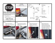
7) In cleared space, layout subframe tubes and<br />
support rails as shown in Figure #6. Position<br />
spacer tube over rectangular blocks on tubes<br />
already attached under support rail before<br />
attaching cross tubes. Remove 2 Hex Head<br />
capscrews 1/4-20 x 3/4” LG. 2 whiz flange nuts<br />
1/4-20 from Bag #1. Drop the capscrews through<br />
lower flange of support rails into short tube. Insert<br />
flange nut inside tube ends and finger tighten. Insert<br />
2 long drive rivets from Bag #1 through ends<br />
of corner braces into the support rail flanges and<br />
through flanges into long cross tube. Two short<br />
rivets for securing support rails to long cross tube.<br />
Make sure the head of the drive rivet is in contact<br />
with the face of corner brace or flange before<br />
hammering rivet pin. Shown in Figure # 7.<br />
8) Use a square for proper frame alignment and<br />
tighten four hex capscrews. Install 4 plastic end<br />
caps from Bag #3 into the open ended tubes.<br />
9) Find the rear hold down angle (3 x 2 x 46.5”)<br />
and place on bottom flanges of support rails near<br />
the first short tube. The two holes in the 2” flange<br />
of angle should line up with holes in support rails.<br />
From Bag #1, remove the two ring pins and insert<br />
them in the holes. See Figure #8.<br />
10) Assemble drawer frame to sub frame. This is<br />
a good time to get a little help from a friend. Grasp<br />
the drawer from both sides and line up the tracks<br />
with the roller bearings and slide into place. If tray is<br />
not running free then recheck the alignment.<br />
11) Remove two eccentric shaft roller bearings<br />
from Bag #3. Install in lower end side hole of<br />
each support rail as shown in Figure #9.<br />
Remember to remove bearings before removing<br />
drawer and always reinstall bearings after reinserting<br />
drawer in pickup.
NOTE: A 6” or More Length<br />
of Steel Rod May be Used<br />
with Hammer to Set Rivet<br />
Rear Hold-Down Angle<br />
Cross Tube<br />
Ring Pin, 1/4”Dia.<br />
Corner Brace<br />
Short Drive Rivet<br />
Long Cross Tube<br />
R.H. Support System<br />
Long Drive Rivet<br />
NOTE: The two Eccentric bearings are not installed until after the<br />
drawer is slid into the sub-frame. You will need a blade type screw driver<br />
and a 1/2” size wrench.<br />
With one hand, rotate bearings until it comes in contact with the bottom<br />
surface of drawer side. Use screwdrivers to hold that position while<br />
tightening the nut.<br />
Repeat procedure for other side.<br />
When these bearings are in place they act as a “safety stop” for<br />
drawer extension.<br />
Eccentric Shaft and<br />
Bearing<br />
R.H. Support Rail<br />
Figure # 7<br />
Figure # 8<br />
Figure # 9<br />
R.H. Support Rail<br />
Whiz Flange Nut<br />
5/16” UNC<br />
Long Cross Tube<br />
12) Remove drawer tray in preparation for installing<br />
drawer bottom. A piece of plywood 5/8” - 3/4” thick is<br />
commonly used. Cut to the size of your tray.<br />
Model No. F/C6548S 45 1/2” x 63”<br />
Model No. F/C7648 45 1/2/” x 74”<br />
Model No. F/C9548 45 1/2” x 93”<br />
Model No. D7348 45 1/2” x 71 1/2”<br />
Model No. D9148 45 1/2” x 89 1/2”<br />
You may get it cut to size at your favorite<br />
lumber yard or do it yourself.<br />
*NOTE: Jotto-Cargo Slides offer optional drawer<br />
bottom options of pre-cut carpet or rubberized mat<br />
to cover plywood. If your Jotto-Cargo Slide is overly<br />
exposed to the elements, we recommend a marine<br />
grade plywood or our optional aluminum interlocking<br />
plank system.<br />
13) After setting drawer bottom in place, remove from<br />
Bag #4 six 1/4 - 20 x 3/4” stainless steel Phillips<br />
Truss head screws and whiz flange nuts. Position<br />
both angle cleat bars at either end of drawer. When<br />
fastened to the front and rear drawer face they will<br />
lock carpet, mat and floor in place. See Figure #10.<br />
14) Slide drawer into support frame assembly. Then,<br />
with some help, set complete unit in the pickup bed.<br />
Center the unit on fore and aft centerline of bed. Push<br />
unit until it makes contact with the front vertical face of<br />
pickup bed. Check for squareness and proper<br />
alignment.<br />
15) Release drawer latch (by pulling “T” handle) and<br />
roll drawer out about 30” or more to provide<br />
comfortable work space when mounting the hold down<br />
angle to front of bed. Remove the six #10 tek screws<br />
(self tapping) and #10 lockwashers from Bag #1. If you<br />
use a power driver to set the screws, set the torque<br />
value to 1/2 or less (depending on type) to prevent<br />
stripping out of pickup sheet metal. 3/16” Dia. pop<br />
rivets are also supplied in case you prefer them<br />
instead of tek screws. To install with rivets, use a 3/16”<br />
Dia. drill bit to make six holes in the front vertical face<br />
of pickup bed. Use the designated holes in mount<br />
angle for your particular brand of pickup. Refer to Figure<br />
#11. In the unlikely event that stripping does occur,<br />
then use a #12 tek screw and lockwasher from your<br />
local hardware store.
3/4” Plywood or<br />
Aluminum Planking<br />
Flange Nut, 1/4-20UNC<br />
Carpet or Mat<br />
Cleat Bar Angle<br />
Figure # 10<br />
Fastener Hole Patterns<br />
Ford F-150/Dodge Ram<br />
Drawer Face/Pull<br />
Tuss Head Screw<br />
1/4-20UNC x 3/4”<br />
NOTE: The holes provided in a hold-down angle are 3/16” Dia. and will<br />
accommodate either pop rivets or #10 Tek screws<br />
R. H. Support Rail<br />
Long Cross Tube<br />
Drive Rivet,<br />
1/2” Long<br />
Chevy Silverado/Nissan<br />
Toyota<br />
Figure # 11<br />
Figure # 13<br />
Figure # 12<br />
Figure # 12<br />
Torque Plate<br />
Drive Rivet, 1/2” Long “Z” Bracket<br />
16) Once hold down angle is mounted, test drawer by<br />
sliding it out until it latches at about 65-70% extension.<br />
Make sure the latching bolts are simultaneously<br />
engaged in larger holes on both support rails. Check<br />
for interference and alignment before proceeding to<br />
next step.<br />
17) Install torque plates on both sides. Remove four<br />
drive rivets from Bag #3. Install per Figure # 12.<br />
18) Remove contents of Bag #4. The drawer and frame<br />
should be together and resting in the desired position<br />
in pickup bed. Place the two “Z” brackets over ends<br />
of long rectangular tube. See Figure # 13. Mark with<br />
pen or center punch the location of holes to be drilled<br />
through truck bed. Drill 4 holes with a 9/32” Dia. drill bit.<br />
* Optional “Z” Bracket location is behind long cross<br />
tube rather than on the end as shown.<br />
Depending on the bed configuration, “Z” brackets may<br />
be mounted on back side of long tube opposite the<br />
torque plates.<br />
NOTE: Always do visual check underneath bed before<br />
drilling. That way no wires or lines will be damaged.<br />
After drilling, bolt the “Z” brackets in place using the 1/4<br />
- 20” x 1” hex bolts. Drop bolts down from top side and<br />
use flatwashers and nylock nuts underneath. Screw in<br />
knobs on top of “z” brackets to secure base frame. *<br />
19) Remove black plastic bolt head covers from Bag #4<br />
and place over the exposed bolt heads on long<br />
rectangular tube and “Z” bracket bolts. These will pop<br />
onto bolt head with finger or thumb pressure.<br />
Congratulations!!!!<br />
You have just assembled and installed the<br />
Jotto-Cargo Slide. The best slide of it’s kind on the<br />
market today! Enjoy for many years!<br />
-------- WARNING -------<br />
SEE WEIGHT DISTRIBUTION DIAGRAM<br />
BEFORE LOADING AND USING TRAY<br />
NO<br />
YES<br />
For technical support call 1.877.455.6886 or e-mail us at<br />
jottoinfo@jottodesk.com<br />
Jotto Desk ®<br />
209 West Easy Street Rogers, Arkansas 72756<br />
Direct: 1.479.246.6472 Fax: 1.479.936.8620