Dodge Ram 2500 & 3500 - 2010-Newer Installation ... - RealTruck.com
Dodge Ram 2500 & 3500 - 2010-Newer Installation ... - RealTruck.com
Dodge Ram 2500 & 3500 - 2010-Newer Installation ... - RealTruck.com
- No tags were found...

Create successful ePaper yourself
Turn your PDF publications into a flip-book with our unique Google optimized e-Paper software.
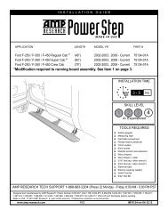
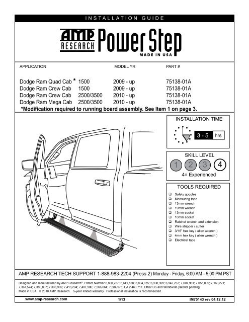
INSTALLATION GUIDEAPPLICATION MODEL YR PART #<strong>Dodge</strong> <strong>Ram</strong> Quad Cab * 1500 2009 - up 75138-01A<strong>Dodge</strong> <strong>Ram</strong> Crew Cab 1500 2009 - up 75138-01A<strong>Dodge</strong> <strong>Ram</strong> Crew Cab <strong>2500</strong>/<strong>3500</strong> <strong>2010</strong> - up 75138-01A<strong>Dodge</strong> <strong>Ram</strong> Mega Cab <strong>2500</strong>/<strong>3500</strong> <strong>2010</strong> - up 75138-01A*Modification required to running board assembly. See Item 1 on page 3.INSTALLATION TIME3 - 5 hrsSKILL LEVEL1 2 3 44= ExperiencedTOOLS REQUIRED Safety goggles Measuring tape 13mm wrench 19mm wrench 13mm socket 10mm socket Ratchet wrench and extension Wire stripper / cutter 3/16” hex key ( allen wrench ) 4mm hex key ( allen wrench ) Electrical tapeAMP RESEARCH TECH SUPPORT 1-888-983-2204 (Press 2) Monday - Friday, 6:00 AM - 5:00 PM PSTDesigned and manufactured by AMP Research ® . Patent Number 6,830,257; 6,641,158; 6,834,875; 6,938,909; 6,942,233; 7,007,961; 7,055,839; 7,163,221;7,367,574; 7,380,807; 7,398,985; 7,413,204; 7,487,986; 7,566,064; 7,584,975; CA 2,463,717. Other US and Worldwide patents pending.Made in USA © <strong>2010</strong> AMP Research 5-year limited warranty. Professional installation is re<strong>com</strong>mended.www.amp-research.<strong>com</strong> 1/13IM75143 rev 04.12.12
AMP RESEARCH POWER STEP – DODGE RAMPARTS LIST AND HARDWARE IDENTIFICATION419-03695-90LWire Harness519-03297-93Type-AController6 x819-03829-90Rivet Nut719-03205-90Rivet Nut Tool8 x1119-03326-90M8 Hex bolt9 x419-03732-90M6x30 Hex Bolt10 x419-03730-90Mounting Insert11 x916-03014-90Washer (SS)12 x819-02802-90Socket CapScrew13 x2019-02805-90Cable Tie (7”)14 x219-03339-90Cable Tie (11”)15 x419-03354-90Posi-Tap TMConnector16 x216-03733-90Support Bracket(not for Mega Cab)17 x217-02777-90Bracket Insert(not for Mega Cab)18 x219-03037-90M8 Flange Bolt(not for Mega Cab)19 x219-02389-90Large Washer(not for Mega Cab)20 x419-02640-90GrommetFOR QUAD CAB ONLY.21 x419-03302-90LED Lamp22 x819-02989-90Butt Connector23 x219-03729-90Roll Pin2419-02849-90Short Hex Bolt2519-02389-90Large Washer2610-00115-60Nylock Nut2716-03701-90Bracket28x416-03789-90Reinforcement Bracket29x419-02784-90Blind Rivetwww.amp-research.<strong>com</strong> 4/13IM75143 rev 04.12.12
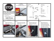
AMP RESEARCH POWER STEP – DODGE RAMNOTE: 1500 Quad Cab installations require additional steps and <strong>com</strong>e with therequired additional hardware. (These parts will not be available in Crew Cab kits.)Please read and carefully follow the instructions in Step 1 for your vehicle model.1500 QUAD CABFollow Steps 2-5 to relocate brake cable and thenproceed with the Power Step installation.1500 CREW CAB& ALL <strong>2500</strong>/<strong>3500</strong> MODELSSkip to Step 6 and proceed with the Power Stepinstallation. Relocation of the brake cable is notneccessary on Crew Cabs.1aWhile holding brake cable adjustment nut withwrench (located on driverside along frame, towardsthe rear), loosen brake cable to allow forslack. Mark position of nut before loosening.1bAfter gaining enough slack, detach brake cable asshown below. This detachment point is locatedjust to the rear of the adjustment nut.2Remove brake cable guide from frame by depressinglocking tabs and sliding guide outthrough hole. Unthread brake cable from framemount.13mm3Attach brake cable guide to supplied Brake CableBracket (23) and mount bracket with suppliedhardware. Reattach brake cable and readjustbrake cable adjustment nut to original position.272426254www.amp-research.<strong>com</strong> 5/13IM75143 rev 04.12.12513mm13mm
HARDWARE MOUNTINGOVERVIEW(passenger side shown)AMP RESEARCH POWER STEP – DODGE RAMLocate forward most andrearward most mountingprovisions on inner sill of truck.Remove tape from sill drain holeat both mounting points.FrontIdler Assembly16Driving AssemblySet Reinforcement Plate in place and locate withrivet nuts. Drill hole using an 1/8” drill bit.NOTE: Driving Linkage Assemblies(with motor) mount in the front; IdlerAssemblies mount in the rear.Once hole is drilled insert a piece of string or wirethrough hole in Reinforcement Plate. Set plate intoposition.28286627 38Set rivet nuts into place for alignment. Insert poprivet through hole in plate and secure in place. Oncepop rivet is installed remove string or wire fromReinforcement Plate. NOTE: Verify plate is pulledfl u sh to the body before securing pop rivet.Assemble Hex Bolt (lubricated with soapy water),Washer, Rivet Tool, and Rivet Nut together asshown and place into hex cutouts in sill. An extraHex Bolt and M8 Washer is supplied to install rivetnuts.782949 10 5www.amp-research.<strong>com</strong> 6/13IM75143 rev 04.12.126
AMP RESEARCH POWER STEP – DODGE RAMWith Rivet Nut Tool held in place with 19mm wrench,tighten Hex Bolt until Rivet Nut deforms and securesitself to the sheet metal (110 in-Lbs. or 4 turns).Remove Hex Bolt and Rivet Nut Tool. Repeat foreach of the four mentioned mounting locations.WARNING: RivetNuts not properlycollapsed will nothold securely tosheet metal.Once rivet nuts are in place use a screwdriver topush back tab in hole to avoid interference withlinkage mount. Next start M8 Hex Bolts and Washersinto installed Rivet Nuts, leaving about 1/2 inchof thread. Make sure washers remain flush to bolt8NOTE: Hold Rivet tool with10 11 wrench while loosening bolt.12 1019mm 13mmWith linkage assembly in hand, insert Hex Bolt and rotate as shown to orient Mounting Insert correctly.Make sure Insert remains in this orientation during next step.11102310913 10 10Linkage <strong>Installation</strong>. With Linkage tilted back asshown and Mounting Insert still oriented correctly,hook two mounting slots of Linkage onto thepre-mounted Hex Bolts.Idler Hex Bolt and Pin Location:Insert Pin into appropiate hole asindicated on label. The bolt will usethe corresponding hole (right, left, orcenter).Tilt Linkage forward, dropping Mounting Insert intosheetmetal slot, and tighten M6 Hex Bolt to 6 ft-lbs.Do not allow bolt to rotate counter-clockwise, as thismay disengage Mounting Insert. Then tighten lowerHex Bolts to 16 ft-lbs with 13mm wrench.9NOTE: Linkage needs to be partially10 14retracted to install.10 15www.amp-research.<strong>com</strong> 7/13IM75143 rev 04.12.1210mm13mm
AMP RESEARCH POWER STEP – DODGE RAMThe jogs in the lower part of the linkages point toward one another, as shown, Drive (motor) Linkagein the Front and Idler Linkage in the Rear. Note: Linkage position described in parts list on page 3.616Slide mounting T-Nut of board into position and attach to linkages. The end of board/end cap willallign fl ush with Rear Linkage.Torque to 10 ft-lbs.(13.5 Nm)712173/16”NOTE: Skip steps 18-22 on Mega Cab models. Mega Cabmodels do not take Support Bracket.9www.amp-research.<strong>com</strong> 8/13IM75143 rev 04.12.12
AMP RESEARCH POWER STEP – DODGE RAMRear Support. Preassemble Bracket Insert withHex Bolt and Washer and insert into body supportmember above Idler Linkage.Position Bracket Insert assembly with the longend of the insert pointing toward the center of thetruck (inboard) leaving enough threads for bracketinstallation.17171981918 SEE MEGA CAB NOTE ABOVE 19 12Position Support Bracket as shown below, restingagainst rear face of Idler Linkage and slotted endaround hanging bolt and washer from step 16.1988With Support Bracket flush to the sheet metal andupper Hex Bolt snug, shift bracket until slot lines upwith the threaded hole. Insert Flange Bolt.16161820 716721With bolts snug and bracket squarely mounted to trucksheet metal and Linkage Assembly, tighten both HexBolts to 16 ft-lbs with 13mm wrench or socket.22 9Torque to 16 ft-lbs.(22 Nm)www.amp-research.<strong>com</strong> 9/13IM75143 rev 04.12.1213mm13mm
On Passenger Side, run Wire Harness leg down andalong underside of the vehicle floor and frame to frontDrive Linkage. Connect harness to motor and secureharness with tie wraps. Route remainder of wire harnesstowards rear linkage assembly for LED lightsOn each side of the vehicle measure from the front edgeof door line on the pinch weld to the specifi ed lenghtsbelow. Measure at 22” for the front LED Light and 64-3/4”for the rear LED Light.35 36464-3/4”22”Drill a 9/32” hole through the pinch weld at markedlocations. Debur all holes.Insert grommet into drilled holes. Insert lamp wiresthrough the grommets. (Silicon lube will help wires slipthrough grommets.)191837 38Affix lamp to rocker panel surface. Make sure lampis affi xed to a flat, clean surface.Using supplied butt connectors, connect the lampwires. Red to Red, Black to Black2120222039 40www.amp-research.<strong>com</strong> 12/13IM75143 rev 04.12.12
AMP RESEARCH POWER STEP – DODGE RAMClose and wrap with conduit and electrical tape.Secure all loose wires with cable ties, with lampwires pulled upward to avoid any wire snagging.Reinstall fuse.41 28 42 29Check that all doors activate the Power Step and the LED Lights work when doors openand close. Reinstall any remaining trim panels.30FINAL SYSTEM CHECKCheck that all doors activate the PowerStep and the LED lights work when doors open and close.NORMAL OPERATION: When the doors open, PowerStep automatically deploys from under the vehicle.When the doors are closed, PowerStep will automatically return to the stowed/retracted position. Note thatthere is a 2-second delay before the PowerStep returns to the stowed/retracted position.CORRECT OPERATION OF LIGHTS: All four lamps will illuminate upon opening any door of vehicle. Lampswill stay on until restowing of both Power Steps or until 5 minutes has expired with the doors open. When thelights timeout after 5 minutes, they can be reillumintated by closing and opening any door of vehicle.32 33www.amp-research.<strong>com</strong> 13/13IM75143 rev 04.12.12
Congratulations on your purchase of thegenuine AMP Research PowerStep!Here’s what you should know...AMP Research PowerStep running boards automatically movewhen the doors are opened to assist entering and exiting the vehicle.Automatic power deploy:The running boards will extend down and out when the doors are opened.Automatic power stow:The running boards will return to the stowed position when the doors are closed. There will be a 2-seconddelay before the running boards move to the stowed position.Automatic stop:If an object is in the way of the moving running board, the running board will automatically stop.To reset, clear any obstruction, then simply open and close the door to resume normal operation.Manually set in the deployed (OUT) position for access to the roof:your foot while at the same time closing the door. To resume normal operation, open and close the door.Maintenance: In adverse conditions, debris such as mud, dirt, and salt may be<strong>com</strong>e trapped in the runningboard mechanism, possibly leading to unwanted noise. If this occurs, manually set the running boards toAvoid spraying the motors directly. After washing, apply silicone spray lubricant to the hinge pivot pins.Do not apply silicone, wax or protectants like Armor All® to the running board stepping surface.Caution! Keep hands away when the running board is in motion.5-YEAR LIMITED WARRANTYAMP RESEARCH warrants this product to be free from defects in material and workmanship for FIVE (5) YEARS FROMDATE OF PURCHASE, provided there has been normal use and proper maintenance. This warranty applies to the originalpurchaser only. All remedies under this warranty are limited to the repair replacement of the product itself, or the repairor replacement of any <strong>com</strong>ponent part thereof, found by the factory to be defective within the time period specified. Thedecision to repair or replace is wholly within the discretion of the manufacturer.for instructions. You must retain proof of purchase and submit a copy with any items returned for warranty work. Upon<strong>com</strong>pletion of warranty work, if any, we will return the repaired or replaced item or items to you freight prepaid. Damageto our products caused by accidents, fire, vandalism, negligence, misinstallation, misuse, Acts of God, or by defective partsnot manufactured by us, is not covered under this warranty.ANY IMPLIED WARRANTIES OF MERCHANTABILITY AND/OR FITNESS FOR A PARTICULAR PURPOSE CREATED HEREBY ARELIMITED IN DURATION TO THE SAME DURATION AND SCOPE AS THE EXPRESS WRITTEN WARRANTY. OUR COMPANY SHALLNOT BE LIABLE FOR ANY INCIDENTAL OR CONSEQUENTIAL DAMAGE.Some states do not allow limitations on how long an implied warranty lasts, or the exclusion or limitation of incidentalor consequential damages, so the above limitations or exclusions may not apply to you. This warranty gives you specificlegal rights, and you may also have other rights that vary from state to state.FOR WARRANTY ISSUES WITH THIS PRODUCT PLEASE CALL AMP RESEARCH CUSTOMER SERVICE 1-800-315-9697WARNINGBe sure to read and precisely follow the provided instructions when installing this product. Failure to do so could place the vehicleoccupants in a potentially dangerous situation. After installing or reinstalling, re-check to insure that the product is properly installed.