Installing The Heavy Duty Roll-Out Tray - Lista
Installing The Heavy Duty Roll-Out Tray - Lista
Installing The Heavy Duty Roll-Out Tray - Lista

Create successful ePaper yourself
Turn your PDF publications into a flip-book with our unique Google optimized e-Paper software.
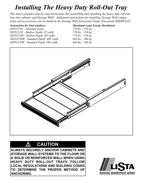
<strong>Installing</strong> <strong>The</strong> <strong>Heavy</strong> <strong>Duty</strong> <strong>Roll</strong>-<strong>Out</strong> <strong>Tray</strong><br />
This insert provides step-by-step instructions for assembling and installing the heavy duty roll-out<br />
tray into cabinets and Storage Wall ® . Additional instructions for installing Storage Wall components<br />
and accessories can be found in the Storage Wall Instruction Guide (Document #MD003A3).<br />
Instructions for Part numbers:<br />
HDTCF/SC - Standard Depth<br />
HDTCF/ST - Shallow Depth, ST width<br />
HDTCF/HS - Shallow Depth, HS width<br />
HDTCF/MW - Standard Depth, MW width<br />
HDTCF/DW - Standard Depth, DW width<br />
CAUTION<br />
ALWAYS SECURELY ANCHOR CABINETS AND<br />
STORAGE WALL SYSTEMS TO THE FLOOR OR<br />
A SOLID OR REINFORCED WALL WHEN USING<br />
HEAVY DUTY ROLL-OUT TRAYS. FOLLOW<br />
LOCAL REGULATIONS AND BUILDING CODES<br />
TO DETERMINE THE PROPER METHOD OF<br />
ANCHORING.<br />
Maximum Load, Evenly Distributed<br />
770 lbs. / 350 kg<br />
770 lbs. / 350 kg<br />
770 lbs. / 350 kg<br />
660 lbs. / 300 kg<br />
660 lbs. / 300 kg
SAFETY PRECAUTIONS<br />
CABINETS AND STORAGE WALL<br />
SECTIONS MUST BE SECURED<br />
TO FLOOR AND/OR WALL PRIOR<br />
TO INSTALLING HEAVY DUTY<br />
ROLL-OUT TRAY.<br />
CABINETS AND STORAGE WALL<br />
SECTIONS MUST BE ANCHORED<br />
IF THEY ARE LOCATED IN AN<br />
AREA THAT IS PRONE TO SEIS-<br />
MIC ACTIVITY.<br />
GLOVES MUST BE WORN DURING<br />
INSTALLATION OF THESE COM-<br />
PONENTS.<br />
DO NOT FULLY EXTEND ROLL-<br />
OUT TRAY UNTIL ALL ASSEMBLY<br />
STEPS ARE COMPLETE.<br />
THIS INSTALLATION MAY<br />
REQUIRE TWO PEOPLE TO<br />
INSTALL ROLL-OUT TRAYS INTO<br />
STORAGE WALL SECTIONS.<br />
Page 2<br />
Hardware Illustrations<br />
Assembly Instructions for <strong>Heavy</strong> <strong>Duty</strong> <strong>Roll</strong>-<strong>Out</strong> <strong>Tray</strong>s<br />
figure 1<br />
1/4–20 x 3/4” socket cap screw with<br />
galvanized retainer bracket<br />
figure 2<br />
5/16–18 x 1/2” socket cap screw<br />
with serrated washer<br />
Hardware included (per tray):<br />
• 2 - 1/4 -20 x 3/4" socket cap screws<br />
• 2 - retainer brackets, galvanized<br />
• 2 - 5/16-18 x 1/2" socket cap screws<br />
• 2 - 5/16 lock washers<br />
Tools and materials required:<br />
• gloves<br />
• mallet<br />
• 1/4”, 3/8” drive socket set or electric drill with 5/16” socket adapter<br />
• tape measure<br />
• 3/16" allen wrench<br />
• 1/4" allen wrench<br />
• 7/16" open end wrench<br />
Storage Wall sections<br />
• Follow instructions in the Storage Wall Instruction Manual to assemble<br />
the Storage Wall sections (if purchased new). Refer to Figure 1 to identify<br />
components and hardware for the heavy duty roll-out tray.<br />
• Install Storage Wall Vertical Side Frames and Universal Panels.<br />
Vertical Side Frames must be anchored to floor or wall<br />
before installing trays (see Storage Wall Instruction Manual)<br />
Gloves should be worn while installing support tracks.<br />
• Install the lowest right or left outside support track orno lower than<br />
2" (50mm) or 2 open slots up from the top edge of the bottom universal<br />
panel (see figure 4). Install support track by sliding the tongues at the rear<br />
of the support track into the slots in the rear vertical side frame. <strong>The</strong> front<br />
slots should then easily slide into the front slots. Be sure that support track<br />
is level. Use a mallet to tap the track into place. Repeat for the other outside<br />
support track.<br />
• Slide the rear bearing of the right or left extension track or through<br />
the cutout in the support track . <strong>The</strong> bearing has to point away from<br />
you (see figure 5).<br />
• Lift the front portion of the extension trackor over the front bearing<br />
of the outside support track or .<br />
• Repeat the last 2 steps for the other extension track.<br />
• Insert galvanized retainer bracket into the first slot in the front vertical<br />
side frame directly above the outside support bracket and push the top<br />
tab into the second slot. Hold the bracket in place with one hand and<br />
insert a 1/4-20 x 3/4” socket cap screw through the hole of the outside<br />
support bracket and secure with a 3/16” allen wrench into the retainer<br />
bracket.<br />
• Extend right and left extension tracks the same distance.<br />
• <strong>Lista</strong> recommends removing tray inserts from the tray before proceeding<br />
with the following steps. Removing tray inserts will make it easier<br />
to install the tray. Two people may be required to install the trays into<br />
the Storage Wall sections.
<strong>Roll</strong>-out <strong>Tray</strong> (1)<br />
Right <strong>Out</strong>side Support Track (1)<br />
Left <strong>Out</strong>side Support Track (1)<br />
Right Extension Track (1)<br />
Left Extension Track (1)<br />
Figure 4<br />
Vertical Side<br />
Frame<br />
<br />
<br />
<br />
Bottom Universal<br />
Panel<br />
Parts List (Quantities)<br />
<br />
<br />
min. distance<br />
from top edge of<br />
bottom universal<br />
panel 2” (50 mm)<br />
or two open slots<br />
<br />
<br />
Galvanized <strong>Tray</strong> Inserts (3 for shallow depth<br />
models or 4 standard models)<br />
1/4–20 x 3/4” socket head screw, retainer<br />
brackets (2 sets)<br />
5/16–18 x 1/2” socket head screw & washers (2)<br />
End cap and IDL (1 of each)<br />
Handle paper label and plastic cover (1 set)<br />
<br />
<br />
<br />
<br />
<br />
tongues<br />
Figure 3<br />
cut-out in outside support track Figure 5<br />
Page 3
(continued)<br />
IMPORTANT: Be sure to<br />
install socket cap screw<br />
before using roll-out tray.<br />
Vertical side<br />
frame<br />
Self drilling/self tapping<br />
hex head washer screw<br />
Figure 6<br />
IDLProfile<br />
Figure 7<br />
Figure 8<br />
• Grasp tray and slide rear left tray bearing behind front bearing of left<br />
extension track . Slide tray up as far as you can and push tray into left<br />
extension track approximately 3-5".<br />
• Align right extension track with the right side of tray bearing and slide<br />
tray upwards behind bearing as far as you can.<br />
• Push the tray assembly in until it is fully engaged.<br />
• <strong>Tray</strong> should roll smoothly in tracks.<br />
CAUTION<br />
<strong>Lista</strong> International Corporation<br />
106 Lowland Street<br />
Holliston, MA 01746<br />
Technical Support: (800) 722-3020, ext. 235 or 233.<br />
E-mail: sales@listaintl.com<br />
Part Number: HDTCF_INST, 04/2000<br />
Document Number: MD017A3, Rev 1<br />
© 2000 <strong>Lista</strong> International, all rights reserved<br />
Be careful not to fully extend the tray until all assembly steps are<br />
complete. <strong>The</strong> tray could disengage from the track and cause<br />
injuries.<br />
• Be sure that rear back panel of tray is pushed in past the hole in extension<br />
track with pem nut. Insert 5/16" socket cap screw and bowed serrated<br />
security washer into pem nut in left and right extension tracks <br />
and . Secure tightly with 1/4" allen wrench (See Figure 6).<br />
• Re-install galvanized tray inserts into tray .<br />
• Remove end cap from handle by carefully prying off with a small flat<br />
head screwdriver.<br />
• Install label and plastic cover into handle by sliding in from one end of<br />
handle.<br />
• Snap-in end cap into the end of the handle.<br />
• If the end cap is difficult to remove, the label and cover can be installed<br />
without removing the end cap. Hold label and cover together and insert<br />
both items under the bottom groove of the handle. Carefully place the top<br />
right corner of the label and cover under the top groove. Using a flat blade<br />
(small screwdriver or pocket knife) press lightly along the length of the<br />
label and cover until they fit snugly into the entire groove.<br />
Instructions for <strong>Installing</strong> Individual Drawer Latch (IDL)<br />
Vertical Profile (Storage Wall System Only)<br />
• To use the IDL option, an IDLvertical profile must be attached to the front<br />
of the vertical side frame (See Figure 7).<br />
• If holes in VSF post are not present, temporarily secure the IDL profile<br />
with vice grip - C-clamps to the VSF post so that holes in profile are centered<br />
to the VSF post. You can use self-drilling/self-tapping hex head<br />
washer screws #12 x 3/4” (i.e. tech screws) (See Figure 8).<br />
• If holes are present, attach the IDL profile to the vertical side frame with<br />
holes pre-punched along the front post. This should be on the same side<br />
that the IDL will be installed (See Figure 7).<br />
• Secure the IDLprofile with 1/4-20 x 5/8” hex head bolts and nuts. Tighten<br />
bolts tightly with ratchet or open end wrench.<br />
Page 4