A Crash Course in Radio Astronomy and Interferometry: 3 ... - NRAO
A Crash Course in Radio Astronomy and Interferometry: 3 ... - NRAO
A Crash Course in Radio Astronomy and Interferometry: 3 ... - NRAO

You also want an ePaper? Increase the reach of your titles
YUMPU automatically turns print PDFs into web optimized ePapers that Google loves.
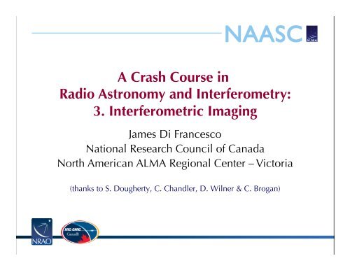
A <strong>Crash</strong> <strong>Course</strong> <strong>in</strong><br />
<strong>Radio</strong> <strong>Astronomy</strong> <strong>and</strong> <strong>Interferometry</strong>:<br />
3. Interferometric Imag<strong>in</strong>g<br />
James Di Francesco<br />
National Research Council of Canada<br />
North American ALMA Regional Center – Victoria<br />
(thanks to S. Dougherty, C. Ch<strong>and</strong>ler, D. Wilner & C. Brogan)
Aperture Synthesis<br />
Aperture Synthesis<br />
• sample V(u,v) at enough po<strong>in</strong>ts to synthesize the equivalent large<br />
aperture of size (u max ,v max )<br />
– 1 pair of telescopes → 1 (u,v) sample at a time<br />
– N telescopes → number of samples = N(N-1)/2<br />
– fill <strong>in</strong> (u,v) plane by mak<strong>in</strong>g use of Earth rotation: Sir<br />
Mart<strong>in</strong> Ryle, 1974 Nobel Prize <strong>in</strong> Physics<br />
– reconfigure physical layout of N telescopes for more<br />
Sir Mart<strong>in</strong> Ryle<br />
1918-1984<br />
2 configurations<br />
of 8 SMA antennas<br />
345 GHz<br />
Dec = -24 deg<br />
2
Imag<strong>in</strong>g<br />
(u,v) Plane Sampl<strong>in</strong>g<br />
• <strong>in</strong> aperture synthesis, V(u,v) samples are limited by number of<br />
telescopes, <strong>and</strong> Earth-sky geometry<br />
– high spatial frequencies:<br />
• maximum angular resolution<br />
– low spatial frequencies:<br />
• extended structures <strong>in</strong>visible<br />
(aka. only a max scale can be<br />
imaged; also ``zero-spac<strong>in</strong>g<br />
problem” = no large scales)<br />
– irregular with<strong>in</strong> high/low limits:<br />
• sampl<strong>in</strong>g theorem violated<br />
• still more <strong>in</strong>formation miss<strong>in</strong>g
Imag<strong>in</strong>g<br />
• sample Fourier doma<strong>in</strong> at discrete po<strong>in</strong>ts, i.e.,<br />
• so, the <strong>in</strong>verse Fourier transform of the ensemble of visibilities is:<br />
I<br />
Formal Description<br />
δ ij (u,v)<br />
• but the convolution theorem tells us:<br />
I I<br />
where (the po<strong>in</strong>t spread function)<br />
Fourier transform of sampled visibilities yields the true sky brightness<br />
convolved with the po<strong>in</strong>t spread function<br />
(the “dirty image” is the true image convolved with the “dirty beam”)
Imag<strong>in</strong>g<br />
b(x,y)<br />
(dirty<br />
beam)<br />
I(x,y)<br />
Dirty Beam <strong>and</strong> Dirty Image<br />
B(u,v)<br />
I D (x,y)<br />
(dirty<br />
image)
Imag<strong>in</strong>g<br />
Dirty Beam Shape <strong>and</strong> N Antennas<br />
2 Antennas
Imag<strong>in</strong>g<br />
Dirty Beam Shape <strong>and</strong> N Antennas<br />
3 Antennas
Imag<strong>in</strong>g<br />
Dirty Beam Shape <strong>and</strong> N Antennas<br />
4 Antennas
Imag<strong>in</strong>g<br />
Dirty Beam Shape <strong>and</strong> N Antennas<br />
5 Antennas
Imag<strong>in</strong>g<br />
Dirty Beam Shape <strong>and</strong> N Antennas<br />
6 Antennas
Imag<strong>in</strong>g<br />
Dirty Beam Shape <strong>and</strong> N Antennas<br />
7 Antennas
Imag<strong>in</strong>g<br />
Dirty Beam Shape <strong>and</strong> N Antennas<br />
8 Antennas
Imag<strong>in</strong>g<br />
Dirty Beam Shape <strong>and</strong> N Antennas<br />
8 Antennas x 6 Samples
Imag<strong>in</strong>g<br />
Dirty Beam Shape <strong>and</strong> N Antennas<br />
8 Antennas x 30 Samples
Imag<strong>in</strong>g<br />
Dirty Beam Shape <strong>and</strong> N Antennas<br />
8 Antennas x 60 Samples
Imag<strong>in</strong>g<br />
Dirty Beam Shape <strong>and</strong> N Antennas<br />
8 Antennas x 120 Samples
Imag<strong>in</strong>g<br />
Dirty Beam Shape <strong>and</strong> N Antennas<br />
8 Antennas x 240 Samples
Imag<strong>in</strong>g<br />
Dirty Beam Shape <strong>and</strong> N Antennas<br />
8 Antennas x 480 Samples
Imag<strong>in</strong>g<br />
How to analyze <strong>in</strong>terferometer data?<br />
• uv plane analysis<br />
– best for “simple” sources, e.g., po<strong>in</strong>t sources, disks<br />
• image plane analysis<br />
– Fourier transform V(u,v) samples to image plane, get I D (x,y)<br />
– but difficult to do science on dirty image<br />
– deconvolve b(x,y) from I D (x,y) to determ<strong>in</strong>e (model of) I(x,y)<br />
visibilities dirty image sky brightness
Imag<strong>in</strong>g<br />
Weight<strong>in</strong>g <strong>and</strong> Taper<strong>in</strong>g<br />
• Visibility Weight<strong>in</strong>g <strong>in</strong> the FT:<br />
– Includ<strong>in</strong>g weight<strong>in</strong>g function W to modify dirty beam sidelobes:<br />
– natural weight<strong>in</strong>g: density of uv-coverage = highest compact flux<br />
sensitivity<br />
– uniform weight<strong>in</strong>g: extent of uv-coverage = highest resolution<br />
– robust weight<strong>in</strong>g: compromise between natural <strong>and</strong> uniform<br />
– taper<strong>in</strong>g: downweights high spatial frequencies = higher<br />
extended flux sensitivity<br />
• imag<strong>in</strong>g parameters provide a lot of freedom<br />
• appropriate choice depends on science goals<br />
• recall that the primary beam FWHM is the “field-of-view” of a<br />
s<strong>in</strong>gle-po<strong>in</strong>t<strong>in</strong>g <strong>in</strong>terferometric image
Imag<strong>in</strong>g<br />
Natural<br />
0.77x0.62<br />
σ = 1.0<br />
Uniform<br />
0.39x0.31<br />
σ = 3.7<br />
Weight<strong>in</strong>g <strong>and</strong> Taper<strong>in</strong>g: Examples<br />
Robust 0<br />
0.41x0.36<br />
σ = 1.6<br />
Robust 0<br />
+ Taper<br />
0.77x0.62<br />
σ = 1.7
~4’<br />
Field of View: S<strong>in</strong>gle Po<strong>in</strong>t<strong>in</strong>g<br />
B68 ALMA s<strong>in</strong>gle po<strong>in</strong>t<strong>in</strong>g<br />
FOV [12 m]<br />
B<strong>and</strong> 3 (54”)<br />
B<strong>and</strong> 6 (27”)<br />
B<strong>and</strong> 7 (18”)<br />
B<strong>and</strong> 9 (9”)
~4’<br />
Field of View: Mosaics<br />
B68 ALMA B<strong>and</strong> 3 mosaic<br />
Nyquist Spac<strong>in</strong>g<br />
= 3 -1/2 (λ/D) rad.<br />
= 29.75” x<br />
(ν/100 GHz) -1<br />
= constant rms<br />
over <strong>in</strong>ner area<br />
Mosaics of up to<br />
50 po<strong>in</strong>t<strong>in</strong>gs OK<br />
for Early Science
Next: Deconvolution