DESIGN OF SLABS - VTU e-Learning
DESIGN OF SLABS - VTU e-Learning
DESIGN OF SLABS - VTU e-Learning

Create successful ePaper yourself
Turn your PDF publications into a flip-book with our unique Google optimized e-Paper software.
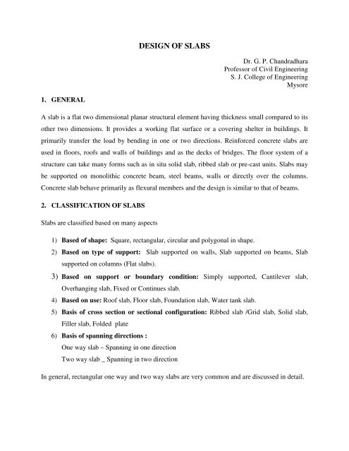
1. GENERAL<br />
<strong>DESIGN</strong> <strong>OF</strong> <strong>SLABS</strong><br />
Dr. G. P. Chandradhara<br />
Professor of Civil Engineering<br />
S. J. College of Engineering<br />
Mysore<br />
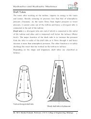
A slab is a flat two dimensional planar structural element having thickness small compared to its<br />
other two dimensions. It provides a working flat surface or a covering shelter in buildings. It<br />
primarily transfer the load by bending in one or two directions. Reinforced concrete slabs are<br />
used in floors, roofs and walls of buildings and as the decks of bridges. The floor system of a<br />
structure can take many forms such as in situ solid slab, ribbed slab or pre-cast units. Slabs may<br />
be supported on monolithic concrete beam, steel beams, walls or directly over the columns.<br />
Concrete slab behave primarily as flexural members and the design is similar to that of beams.<br />
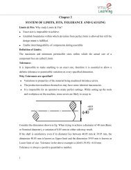
2. CLASSIFICATION <strong>OF</strong> <strong>SLABS</strong><br />
Slabs are classified based on many aspects<br />
1) Based of shape: Square, rectangular, circular and polygonal in shape.<br />
2) Based on type of support: Slab supported on walls, Slab supported on beams, Slab<br />
supported on columns (Flat slabs).<br />
3) Based on support or boundary condition: Simply supported, Cantilever slab,<br />
Overhanging slab, Fixed or Continues slab.<br />
4) Based on use: Roof slab, Floor slab, Foundation slab, Water tank slab.<br />
5) Basis of cross section or sectional configuration: Ribbed slab /Grid slab, Solid slab,<br />
Filler slab, Folded plate<br />
6) Basis of spanning directions :<br />
One way slab – Spanning in one direction<br />
Two way slab _ Spanning in two direction<br />
In general, rectangular one way and two way slabs are very common and are discussed in detail.
3. METHODS <strong>OF</strong> ANALYSIS<br />
The analysis of slabs is extremely complicated because of the influence of number of factors<br />
stated above. Thus the exact (close form) solutions are not easily available. The various methods<br />
are:<br />
a) Classical methods – Levy and Naviers solutions(Plate analysis)<br />
b) Yield line analysis – Used for ultimate /limit analysis<br />
c) Numerical techniques – Finite element and Finite difference method.<br />
d) Semi empirical – Prescribed by codes for practical design which uses coefficients.<br />
4. GENERAL GUIDELINES<br />
a. Effective span of slab :<br />
Effective span of slab shall be lesser of the two<br />
1. l = clear span + d (effective depth )<br />
2. l = Center to center distance between the support<br />
b. Depth of slab:<br />
The depth of slab depends on bending moment and deflection criterion. the trail depth<br />
can be obtained using:<br />
• Effective depth d= Span /((l/d)Basic x modification factor)<br />
• For obtaining modification factor, the percentage of steel for slab can be assumed<br />
from 0.2 to 0.5%<br />
• The effective depth d of two way slabs can also be assumed using cl.24.1,IS 456<br />
provided short span is ≤ 3.5m and loading class is < 3.5KN/m 2<br />
Type of support Fe-250 Fe-415<br />
Simply supported l/35 l/28<br />
continuous l/40 l/32
OR<br />
The following thumb rules can be used<br />
• One way slab d=(l/22) to (l/28).<br />
• Two way simply supported slab d=(l/20) to (l/30)<br />
• Two way restrained slab d=(l/30) to (l/32)<br />
c. Load on slab:<br />
The load on slab comprises of Dead load, floor finish and live load. The loads are calculated<br />
per unit area (load/m 2 ).<br />
Dead load = D x 25 kN/m 2 ( Where D is thickness of slab in m)<br />
Floor finish (Assumed as)= 1 to 2 kN/m 2<br />
Live load (Assumed as) = 3 to 5 kN/m 2 (depending on the occupancy of the building)<br />
5. DETAILING REQUIREMENTS AS PER IS 456 : 2000<br />
a. Nominal Cover :<br />
For Mild exposure – 20 mm<br />
For Moderate exposure – 30 mm<br />
However, if the diameter of bar do not exceed 12 mm, or cover may be reduced by 5 mm.<br />
Thus for main reinforcement up to 12 mm diameter bar and for mild exposure, the nominal<br />
cover is 15 mm<br />
b. Minimum reinforcement : The reinforcement in either direction in slab shall not be less<br />
than<br />
• 0.15% of the total cross sectional area for Fe-250 steel<br />
• 0.12% of the total cross sectional area for Fe-415 & Fe-500 steel.<br />
c. Spacing of bars : The maximum spacing of bars shall not exceed<br />
• Main Steel – 3d or 300 mm whichever is smaller
• Distribution steel –5d or 450 mm whichever is smaller<br />
Where, ‘d’ is the effective depth of slab.<br />
Note: The minimum clear spacing of bars is not kept less than 75 mm (Preferably 100 mm)<br />
though code do not recommend any value.<br />
d. Maximum diameter of bar: The maximum diameter of bar in slab, shall not exceed D/8,<br />
where D is the total thickness of slab.<br />
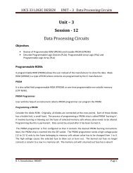
6. BEHAVIOR <strong>OF</strong> ONE WAY SLAB<br />
When a slab is supported only on two parallel apposite edges, it spans only in the direction<br />
perpendicular to two supporting edges. Such a slab is called one way slab. Also, if the slab is<br />
supported on all four edges and the ratio of longer span(ly) to shorter span (lx) i.e ly/lx > 2,<br />
practically the slab spans across the shorter span. Such a slabs are also designed as one way<br />
slabs. In this case, the main reinforcement is provided along the spanning direction to resist one<br />
way bending.<br />
Fig.1: Behavior of one way slab
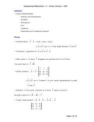
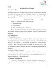
7. BEHAVIOR <strong>OF</strong> TWO WAY <strong>SLABS</strong><br />
A rectangular slab supported on four edge supports, which bends in two orthogonal directions<br />
and deflects in the form of dish or a saucer is called two way slabs. For a two way slab the ratio<br />
of ly/lx shall be ≤ 2.0 .<br />
Fig. 2: Behavior of Two way slab<br />
Since, the slab rest freely on all sides, due to transverse load the corners tend to curl up and lift<br />
up. The slab looses the contact over some region. This is known as lifting of corner. These slabs<br />
are called two way simply supported slabs. If the slabs are cast monolithic with the beams, the<br />
corners of the slab are restrained from lifting. These slabs are called restrained slabs. At corner,<br />
the rotation occurs in both the direction and causes the corners to lift. If the corners of slab are<br />
restrained from lifting, downward reaction results at corner & the end strips gets restrained<br />
against rotation. However, when the ends are restrained and the rotation of central strip still<br />
occurs and causing rotation at corner (slab is acting as unit) the end strip is subjected to torsion.
7.1 Types of Two Way Slab<br />
Two way slabs are classified into two types based on the support conditions:<br />
a) Simply supported slab<br />
b) Restrained slabs<br />
7.1.1 Two way simply supported slabs<br />
The bending moments Mx and My for a rectangular slabs simply supported on all four edges<br />
with corners free to lift or the slabs do not having adequate provisions to prevent lifting of<br />
corners are obtained using<br />
Mx = αx W l 2 x<br />
My = αy W l 2 x<br />
Where, αx and αy are coefficients given in Table 1 (Table 27,IS 456-2000)<br />
W- Total load /unit area<br />
lx & ly – lengths of shorter and longer span.<br />
Table 1 Bending Moment Coefficients for Slabs Spanning in Two Directions at<br />
Right Angles, Simply Supported on Four Sides (Table 27:IS 456-2000)<br />
ly/lx 1.0 1.1 1.2 1.3 1.4 1.5 1.75 2.0 2.5 3.0<br />
αx 0.062 0.074 0.084 0.093 0.099 0.104 0.113 0.118 0.122 0.124<br />
αy 0.062 0.061 0.059 0.055 0.05 1 0.046 0.037 0.029 0.020 0.014<br />
Note: 50% of the tension steel provided at mid span can be curtailed at 0.1lx or 0.1ly from<br />
support.<br />
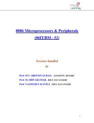
7.1.2 Two way Restrained slabs<br />
When the two way slabs are supported on beam or when the corners of the slabs are prevented<br />
from lifting the bending moment coefficients are obtained from Table 2 (Table 26, IS456-2000)<br />
depending on the type of panel shown in Fig. 3. These coefficients are obtained using yield line
theory. Since, the slabs are restrained; negative moment arises near the supports. The bending<br />
moments are obtained using;<br />
Mx (Negative)= αx (-) W l 2 x<br />
Mx (Positive)= αx (+) W l 2 x<br />
My (Negative)= αy (-) W l 2 x<br />
My (Positive)= αy (+) W l 2 x<br />
Fig. 3: Different Boundary conditions of Two way Restrained slabs
Table 2: Bending moment coefficients for two way restrained slabs ( Table 26, IS 456-2000)<br />
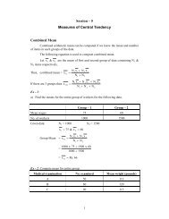
Detailing requirements as per IS 456-2000<br />
a. Slabs are considered as divided in each direction into middle and end strips as shown<br />
below<br />
b. The maximum moments obtained using equations are apply only to middle strip.<br />
c. 50% of the tension reinforcement provided at midspan in the middle strip shall extend in<br />
the lower part of the slab to within 0.25l of a continuous edge or 0.15l of a discontinuous<br />
edge and the remaining 50% shall extend into support.<br />
d. 50% of tension reinforcement at top of a continuous edge shall be extended for a distance<br />
of 0.15l on each side from the support and atleast 50% shall be provided for a distance of<br />
0.3l on each face from the support.
e. At discontinuous edge, negative moment may arise, in general 50% of mid span steel<br />
shall be extended into the span for a distance of 0.1l at top.<br />
f. Minimum steel can be provided in the edge strip<br />
g. Tension steel shall be provided at corner in the form of grid (in two directions) at top and<br />
bottom of slab where the slab is discontinuous at both the edges . This area of steel in<br />
each layer in each direction shall be equal to ¾ the area required (Ast) for maximum mid<br />
span moment. This steel shall extend from the edges for a distance of lx/5. The area of<br />
steel shall be reduced to half (3/8 Astx) at corners containing edges over only one edge is<br />
continuous and other is discontinuous.<br />
Fig. 4: Reinforcement details and strips in Two way restrained slabs
8. ONE WAY CONTINUOUS SLAB<br />
The slabs spanning in one direction and continuous over supports are called one way<br />
continuous slabs.These are idealised as continuous beam of unit width. For slabs of uniform<br />
section which support substantially UDL over three or more spans which do not differ by<br />
more than 15% of the longest, the B.M and S.F are obtained using the coefficients<br />
available in Table 12 and Table 13 of IS 456-2000. For moments at supports where two<br />
unequal spans meet or in case where the slabs are not equally loaded, the average of the two<br />
values for the negative moments at supports may be taken. Alternatively, the moments may<br />
be obtained by moment distribution or any other methods.<br />
Table 3: Bending moment and Shear force coefficients for continuous slabs<br />
( Table 12, Table 13, IS 456-200)
<strong>DESIGN</strong> EXAMPLES<br />
1. Design a simply supported one –way slab over a clear span of 3.5 m. It carries a live load of<br />
4 kN/m 2 and floor finish of 1.5 kN/m 2 . The width of supporting wall is 230 mm. Adopt M-<br />
20 concrete & Fe-415 steel.<br />
1) Trail depth and effective span<br />
Assume approximate depth d =L/26<br />
3500/26 = 134 mm<br />
Assume overall depth D=160 mm & clear cover 15mm for mild exposure<br />
d = 160-15 (cover) -10/2 (dia of Bar/2) =140 mm<br />
Effective span is lesser of the two<br />
i. l =3.5 + 0.23 (width of support) = 3.73 m<br />
ii. l= 3.5 + 0.14 (effective depth) =3.64 m<br />
2) Load on slab<br />
effective span = 3.64 m<br />
i. Self weight of slab = 0.16 x 25 = 4.00<br />
ii. Floor finish = 1.50<br />
iii. Live load = 4.00<br />
= 9.5 kN/m 2<br />
Ultimate load Wu = 9.5 x 1.5 = 14.25 kN/m 2<br />
3) Design bending moment and check for depth<br />
Mu = Wul 2 /8 = 23.60 kN/m<br />
Minimum depth required from BM consideration<br />
d= = = 92.4 > 140 (OK)<br />
4) Area of Reinforcement<br />
Area of steel is obtained using the following equation<br />
Mu=
23.60X10 6 =<br />
23.60X10 6 =50547Ast-749<br />
Ast =<br />
Spacing of 10mm SV=<br />
Solving Ast =504mm 2<br />
Ast=<br />
OR<br />
=505 mm 2<br />
SV= =154 mm<br />
Provide 10mm @ 150 C/C ( )<br />
Provided steel (Ast=524mm 2 ,Pt=0.37%)<br />
Distribution steel@ 0.12% of the Gross area.<br />
=192 mm 2<br />
(420 or 300 ) OK<br />
Spacing of 8 mm SV= =260 mm<br />
Provide 8 mm @260 mm C/C (
(< )<br />
Shear resisted by concrete (Table 19, IS 456-2000)<br />
However for solid slab design shear strength shall be<br />
=<br />
Where, K is obtained from Cl.40.2.1.1, IS 456 -2000<br />
6) Check for deflection<br />
k1- Modification factor for tension steel<br />
k2 – Modification factor for compression steel<br />
k3 – Modification factor for T-sections k4-Only<br />
if span exceeds 10 m (10/span)<br />
7) Check for Development length<br />
Development length<br />
OK<br />
(Fig. 4,cl.32.2.1)<br />
=20X1.38=27.6<br />
=3630/140=25.92<br />
Ld = (0.87x415x10) / (4x1.2x1.6) =470 mm<br />
(OK)
At simple support, where compressive reaction confines the bars, to limit the dia. of bar<br />
Since alternate bars are cranked M1=Mu/2 = 23.2/2 = 11.8 kN.m<br />
V1 = 5.93 kN., Providing 90o bend and 25 mm end cover<br />
Lo = 230/2 – 25 + 3(dia of bar) = 120<br />
470 < (1.3x11.8x106) / (25.9x10³) + 120 = 711 mm O. K.<br />
However, from the end anchorage requirement<br />
extend the bars for a length equal to ld/3 = 156 mm from inner face of support<br />
8) Check for cracking<br />
• Steel is more than 0.12% of the gross area.<br />
• Spacing of steel is < 3d<br />
• Diameter of bar used is < 160/8=20mm<br />
Check for cracking is satisfied.<br />
Reinforcement Detail of One way slab
2. Design a R.C Slab for a room measuring 6.5mX5m. The slab is cast monolithically over the<br />
beams with corners held down. The width of the supporting beam is 230 mm.The slab<br />
carries superimposed load of 4.5kN/m 2 . Use M-20 concrete and Fe-500 Steel.<br />
Since, the ratio of length to width of slab is less than 2.0 and slab is resting on beam, the slab is<br />
designed as two way restrained slab (case-9)<br />
1) Trail depth and effective span<br />
Assume approximate depth d=l/30=5000/30=166mm<br />
Assume D=180 mm & clear cover 15 mm for mild exposure<br />
d=180-15-10/2=160 mm.<br />
Effective span is lesser of the two<br />
i). ly=6.5+0.23=6.73 m , lx=5.0+0.23=5.23 m<br />
ii). ly=6.5+0.16=6.66 m, lx=5+0.16=5.16 m<br />
ly= 6.66 m lx= 5.16 m<br />
2) Load on slab<br />
i). Self weight of slab=0.18X25=4.50 kN/m 2<br />
ii). Super imposed load =4.50<br />
9.0 kN/m 2<br />
Ultimate load wu = 9X1.5=13.5 kN/m 2<br />
3) Design bending moment and check for depth<br />
The boundary condition of slab in all four edges discontinuous (case 9, Table 9.5.2)<br />
Mx = αx Wu l 2 x<br />
My = αy Wu l 2 x<br />
For ly/lx =1.3, αx=0.079<br />
αy=0.056<br />
Positive moment at mid span of short span =Mx= 0.079X13.5X5.16 2<br />
=28.40 kN.m
Positive moment at mid span of longer span =My=0.056X13.5X5.16 2<br />
Minimum depth required from Maximum BM consideration<br />
d= = =103 mm<br />
However, provide d=160 mm<br />
4) Area of Reinforcement<br />
Mu=<br />
Steel along shorter direction (Mx)<br />
28.17X10 6 =<br />
28.40X10 6 =69600Ast-10.875<br />
Solving x=438 mm 2<br />
Provide 10 mm@ 175 C/C (Pt =0.27%)<br />
Steel along longer direction (My)<br />
=20.13 kN.m<br />
Since long span bars are placed above short span bars d=160-10=150<br />
Spacing at 10 mm;<br />
20.13X10 6 =<br />
20.13X10 6 =65250Ast- 10.875<br />
Solving, =327 mm 2<br />
Provide 10 mm @ 240 mm c/c (
7) Check for cracking<br />
k1 =1.5 for pt=0.27% & fs=0.58xfy = 240<br />
( Fig.4, Cl 32.2.1, IS 456-200)<br />
=26X1.5=39<br />
=5.16/0.16=32<br />
Since steel is more than 0.12% of the gross area,<br />
Spacing of steel is
Reinforcement Detail of Two way Restrained slab
3. A hall in a building of clear dimension 14.10 mX9.7 m is to be provided a floor consisting of<br />
a continuous slab cast monolithically with 300 mm wide beams spaced at 3.6 m c/c and<br />
supported on 300 mm wall at ends. The floor is to support a live load of 3 kN/m 2 , Partition<br />
load of 1.0 kN/m 2 and finishes at 1.0 kN/m 2 . Design the continuous slab taking M-20 grade<br />
of concrete and Fe-415 steel.<br />
1) Trail depth and Effective span<br />
Consider 1 m width of slab and effective span shall be taken equal to c/c of beams<br />
Assume trail depth d = l /30 , 3600/30 =120 mm<br />
OR<br />
Assume Pt=0.3%, Modification factor K1 =1.2;<br />
Basic (L/d) ratio for continuous slab =26.<br />
Trail depth d=3600/(26X1.2) = 115 mm.<br />
However, Assume Total depth =150 mm, Dia of bar 10 mm and nominal cover 15 mm<br />
Effective depth d= 150-15-10/2 = 130 mm.<br />
2) Load on slab<br />
a) Total Dead load<br />
i). Self weight of slab= 0.15 x 25 = 3.75 kN/m 2<br />
ii). Floor Finish = 1.00<br />
iii). Partition load = 1.00<br />
Total = 5.75 kN/m 2<br />
Factored Dead load Wd=1.5 x5.75=8.625 kN/m 2<br />
b) Factored live load WL=1.5 x3.00=4.50 kN/m 2<br />
3) Design bending moment<br />
The bending moments and shear force are calculated at different sections using Bending<br />
moment coefficient given in Table 12 and Table 13 of IS 456-2000<br />
B.M at any section
i). B.M at middle of end span<br />
(1)= kN-m<br />
ii). B.M at middle of Interior span(3)=<br />
iii). B.M at support next to end support(2)=<br />
iv). B.M at other intermediate support(4)=<br />
Depth required from maximum B.M considerations<br />
4) Area of Reinforcement<br />
d= (for Fe 415 steel)<br />
d= = 80 mm > 130 mm OK.<br />
From practical consideration, Spacing cannot be varied at different locations. Hence steel is<br />
calculated only at middle of end span and at support next to end support.<br />
Ast at middle of end span<br />
Mu=<br />
15.15X10 6 =<br />
15.15X10 6 =46936Ast, p-7.49<br />
Ast, p =341 mm 2<br />
Spacing of 8 mm = 146 mm<br />
Provide 8 mm @ 145 c/c (349 mm 2 )<br />
Ast at support next to end support<br />
17.66X10 6 =
Solving, Ast, N =402 mm 2<br />
Provide 8 mm @ 280 c/c + 10 mm @ 280 c/c<br />
Area of steel provided= (OK)<br />
Distribution steel @ 0.12 % of gross area<br />
Spacing of 8 mm Sv = mm<br />
Provide 8 mm @ 275 c/c (
N/mm 2<br />
For solid slab shear strength = k.<br />
k = 1.3 (for thickness 150 mm & less )<br />
=1.3 x 0.4 =0.52 N/mm 2 > 0.22 N/mm 2 (OK)<br />
7) Check for cracking<br />
Since steel is more than 0.12% of the gross area,<br />
Spacing of steel is