Tiedown Handbook For Rail Movements - SDDCTEA - U.S. Army
Tiedown Handbook For Rail Movements - SDDCTEA - U.S. Army
Tiedown Handbook For Rail Movements - SDDCTEA - U.S. Army

Create successful ePaper yourself
Turn your PDF publications into a flip-book with our unique Google optimized e-Paper software.
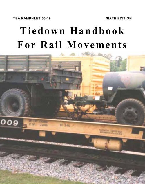
TEA PAMPHLET 55-19 SIXTH EDITION<br />
<strong>Tiedown</strong> <strong>Handbook</strong><br />
<strong>For</strong> <strong>Rail</strong> <strong>Movements</strong>
<strong>SDDCTEA</strong> PAMPHLET 55-19<br />
TIEDOWN HANDBOOK<br />
FOR<br />
RAIL MOVEMENTS<br />
SIXTH EDITION<br />
September 2003<br />
(Electronically Revised April 2010)<br />
John Miget<br />
Mr. Robert E. Kerr<br />
Mr. Philip Raiford<br />
Mr. John T. H. Germanos<br />
Mr. James McGee<br />
Ms. Jennifer L. Napiecek<br />
Mr. Terry Jenkins<br />
_____________________________________________________________________<br />
MILLITARY SURFACE DEPLYMENT AND DISTRIBUTION COMMAND<br />
TRANSPORTATION ENGINEERING AGENCY<br />
SCOTT AIR FORCE BASE, ILLINOIS
SIXTH EDITION <strong>SDDCTEA</strong> PAMPHLET 55-19<br />
The publications in this series are:<br />
Director<br />
Military Surface Deployment and Distribution Command<br />
Transportation Engineering Agency<br />
ATTN: <strong>SDDCTEA</strong> - DPE (J. Miget)<br />
Building 1990, 709 Ward Drive<br />
Scott AFB, IL 62225<br />
Telephone: DSN 770-5255, 618-220-5255, or 1-800-722-0727<br />
E-mail: john.miget@us.army.mil<br />
FAX: DSN 770-5551 or 618-220-5551<br />
TEA PAM 55-19, <strong>Tiedown</strong> <strong>Handbook</strong> for <strong>Rail</strong> Movement<br />
TEA PAM 55-20, <strong>Tiedown</strong> <strong>Handbook</strong> for Truck <strong>Movements</strong><br />
TEA PAM 55-21, Lifting and <strong>Tiedown</strong> of U.S. Military Helicopters<br />
TEA PAM 55-22, Lifting <strong>Handbook</strong> for Marine <strong>Movements</strong>/Lashing <strong>Handbook</strong> for<br />
Marine <strong>Movements</strong><br />
TEA PAM 55-23, Containerization of Military Vehicles<br />
TEA PAM 55-24, Vehicle Preparation <strong>Handbook</strong> for Fixed Wing Air <strong>Movements</strong><br />
TB-55-46-1, Standard Characteristics for Transportability of Military Equipment is<br />
available in compact disc and contains all of the 55-pamphlet series. It also includes<br />
the Ports for National Defense, TEA 70-1, 700-2, and 700-5.<br />
_____________________<br />
Local reproduction is authorized<br />
This and other Government publications are not copyrighted<br />
First edition published May 1989, with green camouflaged cover<br />
Second edition published June 1991, with side-bound brown camouflaged cover<br />
Second edition, 2nd printing, May 1992, with top-bound brown camouflaged cover<br />
Third edition, published March 1995, with light tan cover<br />
Fourth edition, published April 1997, with same light tan cover<br />
Fifth edition, published May 2000, with darker brown cover<br />
ii
SIXTH EDITION <strong>SDDCTEA</strong> PAMPHLET 55-19<br />
Preface<br />
This is the sixth edition of the pamphlet. It has been reorganized to improve<br />
utility, includes new information and figures, and eliminates wooden blocking methods<br />
of securement. However, do not destroy the earlier editions because they are still usable.<br />
This pamphlet will aid the soldier in meeting the Association of American <strong>Rail</strong>roads<br />
(AAR) rules thereby ensuring safe rail transport of equipment. It contains general<br />
information, procedures, and figures for the correct tiedown of military equipment on<br />
railcars.<br />
This pamphlet covers minimum standards; your local railroad may require additional<br />
securement based on the condition of the railcar or other factors that cannot be<br />
standardized. The pamphlet is not designed to cover every vehicle in the US <strong>Army</strong><br />
inventory. The vehicles covered in this pamphlet are those most commonly transported<br />
by rail. When in doubt, check the AAR Loading Rules or check with the mechanical<br />
department of the railroad transporting your equipment.<br />
In this edition, we have kept the chain-tiedown information from the earlier editions<br />
while eliminating the blocking sections. Blocking and wire rope (as a primary tiedown)<br />
methods of vehicle securement are rarely used for military vehicles anymore, since chainequipped<br />
flatcars have become widely available. Wire rope continues as a secondary<br />
tiedown material for items such as gun turrets and secondary loads. We will maintain the<br />
fifth edition on our web site for wire rope and blocking reference. On each tiedown<br />
figure, we have updated the pertinent figure and section numbers from the AAR loading<br />
rules for cross referencing.<br />
The earlier editions lack the above changes, but they may satisfy your other needs,<br />
since many of the chain tiedown methods are unchanged. You may want to compare<br />
the sixth edition with the earlier editions to annotate changes in your earlier pamphlets,<br />
but please note, the page numbers are radically different. Because of printing costs, we<br />
are printing only a limited supply of the sixth edition. Please feel free to make copies<br />
of the pamphlet at your own discretion.<br />
We invite users of this pamphlet to recommend changes and submit comments at<br />
http://www2.tea.army.mil/pubs/Feedback.asp. This and other publications available<br />
on the Internet at http:// www.tea.army.mil/ in Adobe Acrobat Reader (.pdf) format. The<br />
pamphlets are specifically at http://www.tea.army.mil/pubs/default.asp. Between<br />
printings, the most current information can always be found online.<br />
iii
SIXTH EDITION <strong>SDDCTEA</strong> PAMPHLET 55-19<br />
Contents<br />
Page<br />
Preface ............................................................................................................................. iii<br />
List of Illustrations ........................................................................................................ viii<br />
What is That Called? ....................................................................................................... ix<br />
Section I. Requirements for All Equipment ...................................................................... 1<br />
Section II. Wheeled Vehicles ......................................................................................... 11<br />
Section III. Tracked Vehicles ......................................................................................... 13<br />
Section IV. Tools for <strong>Rail</strong> Loading ................................................................................ 17<br />
Table 1. Suggested CONUS <strong>Rail</strong> Loading Toolkit ......................................................... 17<br />
Section V. Tips and Common Mistakes ......................................................................... 21<br />
Section VI. Comparison of the <strong>Rail</strong> Shock Environment ............................................... 25<br />
Section VII. Spanners ..................................................................................................... 27<br />
Section VIII. Loading Ramp ........................................................................................... 29<br />
Section IX. Flatcar Types ............................................................................................... 30<br />
Section X. Loading and <strong>Tiedown</strong> Checklist ................................................................... 34<br />
Section XI. Practical Tips ............................................................................................... 35<br />
Appendix A. Trucks and Trailers ................................................................................. A-1<br />
Trucks Weighing up to 80,000 Pounds .................................................................... A-2<br />
M1074/M1075 PLS and M1120 HEMTT LHS Truck ............................................. A-3<br />
M1076 Palletized Load System (PLS) Trailer ......................................................... A-4<br />
M1070 Tractor ......................................................................................................... A-5<br />
M1000 Trailer .......................................................................................................... A-6<br />
Logistics Vehicle System ......................................................................................... A-7<br />
Trailer Attached to Prime Mover ............................................................................. A-8<br />
Semitrailer Attached to Prime Mover ...................................................................... A-9<br />
Trailer on Flat Car (TOFC) ................................................................................... A-10<br />
Trailers, M872, Double Stacked ............................................................................ A-11<br />
M 129A4 and M 1063 Semitrailers ........................................................................ A-12<br />
iv
SIXTH EDITION <strong>SDDCTEA</strong> PAMPHLET 55-19<br />
(Contents Continued)<br />
Appendix B. Tracked and Wheeled Armored Vehicles ................................................ B-1<br />
Tracked Vehicles up to 30,000 lb ............................................................................ B-2<br />
M577 and M1068 Ramp Securement ...................................................................... B-3<br />
Tanks and Similar Units 30,000 to 60,000 lb ........................................................... B-4<br />
Tanks and Similar Units 60,000 to 100,000 lb ......................................................... B-5<br />
DODX 40000-Series Flatcar Checklist .................................................................... B-6<br />
Tracked Vehicles Over 100,000 lb ........................................................................... B-7<br />
M1 Tanks with Optional Link (Ring) and M88 ....................................................... B-8<br />
Tracked Vehicles Over 100,000 lb without the Link ............................................... B-9<br />
M1 with Mine Clearing Blade System ....................................................................B-10<br />
M728 Front .............................................................................................................B-11<br />
M60 Tanks, AVLB, and Rear of M728 ..................................................................B-11<br />
M109A6 Paladin Howitzer .....................................................................................B-12<br />
Stryker ....................................................................................................................B-13<br />
Appendix C. Materials Handling and Construction Equipment and<br />
Non-Vehicles ........................................................................................................... C-1<br />
Variable Reach <strong>For</strong>klift Truck ................................................................................. C-2<br />
Wheel-Mounted Crane (25- and 35-ton) .................................................................. C-3<br />
Tractors, <strong>For</strong>klifts, Loaders, and so forth ................................................................. C-4<br />
Motor Grader ........................................................................................................... C-5<br />
Scraper (Earthmover) ............................................................................................... C-6<br />
D-7 Caterpillar Dozer .............................................................................................. C-7<br />
CONEX or ISU Container on 5-Ton Trucks ............................................................ C-8<br />
Kalmar Rough Terrain Container Handler (RTCH) ................................................. C-9<br />
Improved Ribbon Bridge ........................................................................................C-10<br />
Index ....................................................................................................................... Index-1<br />
v<br />
Page
SIXTH EDITION <strong>SDDCTEA</strong> PAMPHLET 55-19<br />
List of Illustrations<br />
vi<br />
Page<br />
Figure 1. Brake wheel clearance ................................................................................. 2<br />
Figure 2. Angle of 45 degrees in the side view .......................................................... 4<br />
Figure 3. Inverted tiedown on the trailer .................................................................... 5<br />
Figure 4. Complete loop wire rope assembly ............................................................. 6<br />
Figure 5. Chain hoist and cable gripper ..................................................................... 6<br />
Figure 6. Proper securement of grabhook and chain link ........................................... 7<br />
Figure 7. Turnbuckle .................................................................................................. 7<br />
Figure 8. Chain anchor and chain anchor channel ...................................................... 7<br />
Figure 9. Turnbuckle locking sleeves ........................................................................ 9<br />
Figure 10. Grate/Lock Chock .................................................................................................................................... 12<br />
Figure 11. Slip hooks with the point down ............................................................................................................................. 1 5<br />
Figure 12. Correct position of chain anchor winch ................................................................................. 23<br />
Figure 13. Six -foot aluminum spanner ............................................................................................................ 27<br />
Figure 14. Ten -foot aluminum spanner ........................................................................................................... 28<br />
Figure 15. Steel end ramp for wheeled and heavy tracked vehicles ......................................... 29<br />
Figure 16. DODX 41000 -series 68 -foot flatcar ...................................................................................... 30<br />
Figure 17. DODX 42000-series 89 -foot flatcar ........................................................................................ 31<br />
Figure 18. DODX 40000 -series 68 -foot flatcar ...................................................................................... 31<br />
Figure 19. OTTX 60 -foot flatcar .......................................................................................................................... 32<br />
Figure 20. ITTX 89 -foot flatcar ............................................................................................................................ 32<br />
Figure 21. HTTX 60 -foot flatcar .......................................................................................................................... 33<br />
Figure 22. TTDX 89 -foot flatcar ............................................................................................................................. 33
SIXTH EDITION <strong>SDDCTEA</strong> PAMPHLET 55-19<br />
Round pin anchor shackle<br />
(not recommended for<br />
rail tiedown)<br />
What is That Called?<br />
Safety anchor shackle<br />
vii<br />
Screw pin anchor shackle<br />
Must have nut<br />
and cotter pin.<br />
[To meet<br />
MIL-STD-<br />
209, the nut<br />
must be<br />
welded on.]
SIXTH EDITION <strong>SDDCTEA</strong> PAMPHLET 55-19<br />
Notes<br />
viii
SIXTH EDITION <strong>SDDCTEA</strong> PAMPHLET 55-19<br />
Section I. Requirements for All Equipment<br />
A. This pamphlet provides users with the proper methods for securing wheeled and<br />
tracked vehicles on the chain-equipped flatcars that are now widely available to the military. It<br />
contains basic information from the Association of American <strong>Rail</strong>roads (AAR) 1 and from<br />
experience gained through monitoring many military rail loadouts during deployments.<br />
B. Remember, all equipment loaded onto flatcars must be firmly and properly secured to<br />
counteract longitudinal, lateral, and vertical forces. AAR General Rules require both the rail<br />
carrier (See footnote 1, Rule 1.2.2, Section No. 1) and the shipper (See footnote 1, Rule 1.2.3,<br />
Section No. 1) to comply with all applicable loading rules and observe the drawings and<br />
specifications of applicable figures. The AAR rules are divided into two categories: “General<br />
Rules” (Section No. 1) covering the approved materials and methods of load securement<br />
and “figures” (Section No. 2 through 7) covering specific commodities including items such<br />
as military vehicles and equipment. The AAR rules are mandatory for Government<br />
shippers. Flatcars loaded with your equipment will not move until the railroad inspects and<br />
accepts them as safe loads. The railroad inspector has the final word if a specific figure is not<br />
involved. This pamphlet was published in accordance with the AAR loading rules; however,<br />
follow the AAR loading rules if any conflict arises with this pamphlet. 2 If, in such a conflict,<br />
you feel you have followed all the rules and want a second opinion or some help resolving the<br />
issue, call the DODAAR Representative, Mr. John Miget at (618) 220-5255 or DSN 770-<br />
5255.<br />
C. The following general procedures apply to all types of flatcars.<br />
1. Gearshift Levers and Brakes<br />
Place gearshift levers of automatic or manual transmissions in neutral and secure with wire.<br />
________________________________<br />
1 AAR Open Top Loading Rules Manual (OTLRM), Section No. 1, General Rules for Loading<br />
All Commodities; Section No. 3, Rules for Loading Construction and Farm Machinery;<br />
Section No. 6, Rules for Loading Military Equipment and Materiel; and Section No. 7, Rules<br />
for Loading All Commodities on Open Top Trailers and Containers for <strong>Rail</strong> Transport. Toll<br />
free 877-999-8824 (Washington, DC: AAR, Revised Annually.) Reference is made<br />
throughout this pamphlet to the underlying provisions in the AAR OTLRM.<br />
2See footnote 1.<br />
9
SIXTH EDITION <strong>SDDCTEA</strong> PAMPHLET 55-19<br />
Set all parking brakes and then wire tie or block the hand levers. Setting the brakes is a<br />
precaution against the vehicle rolling inadvertently and not part of the securement. Generally,<br />
set the brakes after the chains are tightened, however, some vehicles require engine power<br />
to set the brakes, which may be set once the vehicle is spotted [Never set the test item<br />
brakes when performing the MIL-STD-810 rail impact test. This verifies that brakes are not<br />
part of the securement.]<br />
2. Brake Wheel<br />
Allow a 12-inch minimum clearance from the end of the car, 6 inches around and above<br />
the brake wheel, and 4 inches below the brake wheel (Fig 1). Note that side-mounted brake<br />
lever clearance need not be taken into account. (See footnote 1, Rule 2.1, Section No. 1)<br />
3. Vehicle Spacing<br />
Figure 1. Brake wheel clearance.<br />
The AAR rules state: “1.2.22 Separate piles or units loaded on one car may be secured<br />
to different specific figures or General Rules and located not closer than 2 feet to the adjacent<br />
pile or unit. Vehicles with spring suspensions secured to different figures or General Rules<br />
may be loaded closer than 2 feet but not less than 10 in. apart. 1.2.23 Cargo such as trailers<br />
and fork trucks may be loaded with the tongue or forks beneath the next vehicle, provided<br />
that points where the vehicles may touch are separated by a minimum horizontal distance of<br />
10 in. and the tongue or forks are secured against vertical displacement.”<br />
10
SIXTH EDITION <strong>SDDCTEA</strong> PAMPHLET 55-19<br />
4. Securing Movable Structure<br />
Equipment with rotating parts, such as tank turrets, and movable parts, such as crane<br />
outriggers and booms, must have those parts positively secured, usually with wire rope.<br />
(rules 6.1 to 6.3) This prevents the parts from moving out or up during shipment. Serious<br />
accidents can result from parts striking bridges, structures, or passing trains.<br />
5. <strong>For</strong>ty-Five Degree <strong>Tiedown</strong> Angle<br />
Place the vehicles on the flatcar so the tiedown wire rope or chain makes<br />
approximately a 45 degree angle with the flatcar's deck when viewed from the side.<br />
Measuring by eye is usually good enough. If you want to layout the correct angle with a<br />
tape measure, make the longitudinal distance from the point the tiedown attaches to the<br />
deck to the tiedown provision on the vehicle equal to the vertical distance from the deck to<br />
the provision (Fig 2). Do not cross the tiedowns.<br />
6. Inverted <strong>Tiedown</strong>s<br />
Inverted tiedowns are tiedown chains or wire ropes that are secured under the<br />
vehicle rather than out, away from the vehicle (Fig 3). Inverted tiedowns are only<br />
appropriate in cases in which the tiedown does not contact any part of the vehicle except the<br />
tiedown provision. Do not use inverted tiedowns if the tiedown bears on the bottom of the<br />
bumper or frame of the vehicle. <strong>For</strong> example, some trailers do have tiedown provisions that<br />
are mounted below the frame such that inverted tiedowns can be used. Another<br />
consideration is the vehicle ground clearance. To use inverted tiedowns, there must be<br />
enough space under the vehicle for a soldier to adequately secure the tiedowns.<br />
7. <strong>Tiedown</strong> Provisions<br />
The procedures in this pamphlet generally cover equipment that was manufactured<br />
to meet MIL-STD-209, Interface Standard for Lifting and <strong>Tiedown</strong> Provisions. MIL-STD-<br />
209 provides for adequate strength tiedown provisions for all modes of transport including<br />
rail. Some equipment requires specialized procedures, which will be described on a MIL-<br />
STD-209 data plate attached to the equipment. MIL-STD-209 is available at:<br />
http://www.tea.army.mil/pubs/nr/deploy/transinstruction/MIL-STD-209K22feb05.pdf<br />
11
SIXTH EDITION <strong>SDDCTEA</strong> PAMPHLET 55-19<br />
Figure 2. Angle of 45 degrees in the side view; the dimensions shown are all equal.<br />
12
SIXTH EDITION <strong>SDDCTEA</strong> PAMPHLET 55-19<br />
D. WIRE ROPE<br />
Figure 3. Inverted tiedown on the trailer.<br />
Wire rope is used to secure movable parts on equipment, such as the barrel and turret on<br />
the M 1 tank and the rear door (ramp) on the M577 tracked vehicle. Secure the wire rope using<br />
clamps. Apply the clamps, also called clips, fist distance apart, with the saddle against the<br />
tension-bearing side of the wire rope and the U-bolt against the dead end. The clamp must be<br />
the same size as the wire rope being used (fig4). Tension the wire rope by pulling tight by<br />
hand for movable parts mentioned above. <strong>For</strong> secondary loads, tension the wire rope using a<br />
hoist (chain or wire rope) with two cable grippers, as shown in figure 5. A properly tensioned<br />
tiedown will deflect no more than about an inch with the weight of a person standing on it. Be<br />
sure that at least 24 inches of wire rope overlap to allow proper application of cable clamps.<br />
Alternately tighten the nuts and torque cable clamps to the following guideline values:<br />
45 foot-pounds for 3/8-inch wire rope<br />
65 foot-pounds for 1/2-inch wire rope<br />
130 foot-pounds for 5/8-inch wire rope<br />
If the clamps break before reaching the above torques, use six instead of four clamps for a<br />
complete loop and torque to a value just below the breaking point.<br />
13
SIXTH EDITION <strong>SDDCTEA</strong> PAMPHLET 55-19<br />
Figure 4. Complete Loop Wire Rope Assembly.<br />
Figure 5. Chain Hoist and Cable Gripper.<br />
E. CHAIN TIEDOWN<br />
Most CONUS chain-equipped flatcars have either 3/8- or 1/2-inch steel alloy chains.<br />
Apply chain hooks over the vehicle tiedown shackles, rather than under. Wire (or secure by<br />
other suitable means such as nylon tie straps) the grabhook to the chain link, as shown in<br />
figure 6, to prevent disengagement. If turnbuckles (used to tighten chains) are not equipped<br />
with jamnuts (Fig 7) or a locking device, they must be wired to prevent them from<br />
loosening.<br />
Apply tiedown chains symmetrically around the vehicle with an angle from deck to chain<br />
of about 45 degrees. Do not cross the chains. Completely seat the chain anchors in the<br />
channels, as shown in figure 8. When attaching chains to the vehicle, secure the shortest<br />
chains first and the longest chains last. A properly tensioned tiedown will deflect no more than<br />
about an inch with the weight of a person standing on it.<br />
14
SIXTH EDITION <strong>SDDCTEA</strong> PAMPHLET 55-19<br />
Figure 8. Chain anchor and chain anchor channel.<br />
15
SIXTH EDITION <strong>SDDCTEA</strong> PAMPHLET 55-19<br />
The general guidelines for securing wheeled vehicles on chain-equipped cars by<br />
diameter of chains are given in the following table (See footnote 1, page 1, Figure 88-B,<br />
Section No. 6):<br />
Vehicle Weight<br />
Ranges (lb)<br />
16<br />
Alloy Steel Chain<br />
Dia Minimum Working<br />
(in.) Load Limit (lb)<br />
0-8,500 3/8 6,600 4<br />
8,500-16,000 3/8 9,000 4<br />
16,000-25,000 3/8 9,000 8<br />
16,000-25,000 1/2 11,250 4<br />
25,000-40,000 1/2 13,750 4<br />
40,000-55,000 1/2 13,750 8<br />
55,000-80,000 1/2 13,750 12<br />
Number of Chains<br />
Required Per Vehicle<br />
<strong>For</strong> vehicles not covered above, use the following formula to determine the number of<br />
chains required (See footnote 1, page 1, Rule 5.3, Section No. 1). The weight of <strong>Army</strong><br />
equipment is printed on bar-code labels applied to both the front and side of each item. The<br />
minimum breaking [force] strength of most alloy chain is about four times the working<br />
load limit (WLL), and the proof load is typically two times the WLL. Chain-equipped flatcars<br />
used to be stenciled with the proof [test] load of the chains and the AAR figures were often<br />
in terms of proof loads. If you have a known proof load for a chain, divide the proof load by<br />
two to get the WLL for that chain. The National Association of Chain Manufacturers<br />
(NACM) states that “The Proof Test and Minimum Breaking <strong>For</strong>ce shall not be used as<br />
criteria for service or design purposes.”<br />
<br />
<br />
2<br />
<br />
The tables provided with the figures in appendix A, B, or C are based on this formula<br />
or on specific figures. However, when using this formula in the field, the user must realize<br />
that it yields the least number of chains required. Most vehicles have four tiedown provisions,<br />
and each provision must have the same number of chains attached to it. Also, the number of<br />
chains restraining movement in one direction (either longitudinal or lateral) must equal the<br />
number in the opposite direction (this is called symmetry). This usually results in the number<br />
of chains required being a multiple of four, that is 4, 8, 12, 16, and so forth. If the resulting
SIXTH EDITION <strong>SDDCTEA</strong> PAMPHLET 55-19<br />
number of chains derived from the formula does not provide for a symmetrical configuration,<br />
add chains such that each tiedown has the same number and equal numbers oppose each<br />
other. <strong>For</strong> example, if the formula yields 9 chains required, use 12 chains to establish<br />
symmetry about the 4 tiedown provisions.<br />
The DODX 41000- and DODX 42000-series flatcars and repaired chains on some of the<br />
DODX 40000-series flatcars are equipped with turnbuckle locking sleeves as shown in figure<br />
9. The lock nut (if present) need not be used if the locking sleeve is properly applied.<br />
As you remove chains preparing to unload flatcars, place the chains into the anchor<br />
channels, so the chains cannot fall off the side of the car. Chains hanging off the side of the<br />
cars can cause injuries, cause derailments, and destroy railroad infrastructure.<br />
Unlocked. Notice that the Locked<br />
notches on the sleeve are<br />
resting on the ears and the turnbuckle is free to turn. To lock, slide the sleeve up, clear<br />
of the ears, and rotate it 1/4 turn, then slide the sleeve down into the locked position.<br />
Figure 9. Turnbuckle locking sleeves.<br />
17
SIXTH EDITION <strong>SDDCTEA</strong> PAMPHLET 55-19<br />
F. STEEL BANDING/STRAPPING<br />
Steel banding can be used to secure secondary loads and to prevent some items from<br />
extending out over the flatcar sides. <strong>For</strong> instance, expansible vans are often banded to prevent<br />
the sides from expanding during rail transport. Rule 17 in Section No. 1 (see footnote 1, page<br />
1) explains the requirements for banding. Anew part of the rule requires periodic testing of<br />
the sealing tools to make sure they continue to produce joints of adequate strength. The<br />
following excerpt gives some of the detailed requirements:<br />
“17.2.9.4 Tool and Joint Condition Testing"<br />
17.2.9.4.1 The compatibility and condition of the materials and joint-making tools for<br />
load securement bands must be verified. This is to be done by subjecting sample band joints<br />
to laboratory testing at periodic intervals to ensure that minimum joint strength is being<br />
consistently obtained.<br />
17.2.9.4.2 Testing is to be done on at least an annual basis, or after a maximum cycle<br />
time of 3,000 applications, whichever occurs first. Testing is to be conducted in accordance<br />
with Rule 17.4, except as noted here regarding the number of test samples and test-record<br />
handling. Testing is to be performed by either the banding or tool manufacturer, or other<br />
certified testing facility. The latter may include a user’s own test equipment, provided all<br />
required test functions can be achieved, and evidence of industry recognized certification<br />
of the test equipment can be readily produced upon request by the AAR or its designated<br />
representative.<br />
17.2.9.4.3 Users must maintain documentation of all test results for the most recent 2year<br />
period. Current test records of the results of each individually identified tool are to<br />
be maintained and made available for inspection upon request.<br />
17.2.9.4.4 Each joint-making tool is to be stamped or otherwise permanently marked with<br />
a distinctive and legible identification mark or serial number. A minimum of three band -<br />
joint samples, made with each tool used in the application of steel bands on loads for rail<br />
transport, must be subjected to testing. If a tool is used to make more than one type or size<br />
of joint, each type and size must be tested accordingly.<br />
17.2.9.4.5 All sample band joints must be made using AAR-approved banding. Each<br />
sample is to be at least 18 in. long with the joint centered between the ends of the sample.<br />
Each sample must be legibly marked with the identification of the equipment with which<br />
the joint was actually made. This information is to be verified and documented in the record<br />
of testing by the tester, and attested to by the tester signing the test report.”<br />
18
SIXTH EDITION <strong>SDDCTEA</strong> PAMPHLET 55-19<br />
Section II. Wheeled Vehicles<br />
All wheeled vehicles must have their tires fully inflated to highway pressure for rail<br />
transport. The tires must be capable of holding that pressure for at least the length of the<br />
trip. Tires are a part of the securement of the vehicle in that, if a tire goes flat, it will leave<br />
the tiedowns loose. Also, flat tires have started fires on moving trains by rubbing on the<br />
flatcar deck.<br />
A. TRAILERS AND SEMITRAILERS<br />
Most units prefer to transport trailers attached to their prime mover as shown in<br />
appendix A (pp. A-8 and A-9). This minimizes the loading and unloading time and<br />
generally simplifies the tiedown procedure by eliminating any blocking required to support<br />
the lunette or kingpin. Semitrailer landing legs cannot bear the shock of rail movement and<br />
must be raised at least 4 inches above the deck of the flatcar.<br />
Semitrailers that do not have dedicated prime movers can be shipped on specialized<br />
flatcars with retractable hitches or stanchions (p. A-10). The entire restraint is provided by<br />
the hitch being locked on the semitrailer kingpin. This method of loading is called traileron-flatcar<br />
(TOFC). The hitches can only accommodate 2-inch kingpins and semitrailer<br />
gross weights up to 65,000 pounds. Trailers shipped by TOFC must meet AAR<br />
specification M-931, “Highway Trailers, All Types, for TOFC Service.” Trailers meeting<br />
the latest version of M-931, 1 May 1999, will have a “certification plate” adjacent to the<br />
DOT certification label. Some semitrailers can exceed the weight limit and may have 3-1<br />
/2-inch kingpins, and thus, cannot be shipped by TOFC.<br />
The M969A2, M969A3, and the M967A2 are the only semitrailer tankers that are<br />
capable of rail transport loaded with fuel. Shipment of tankers by TOFC with fuel<br />
requires special permission from the Federal <strong>Rail</strong>road Administration (FRA) through<br />
MTMC Operations.<br />
B. VEHICLES ON BI-LEVEL FLATCARS<br />
Bi-level flatcars may be used for smaller vehicles. The tiedown procedure is the same<br />
as for single-deck chain-tiedown flatcars. The types of chain assemblies on bi-level flatcars<br />
vary widely. Your local railroad can provide details about the chain assemblies on and the<br />
dimensions of bi-level flatcars. Before using bi-level flatcars, check their dimensions to<br />
be sure sufficient clearance exists for the driver to get into or out of the vehicle after the<br />
vehicle is loaded on the flatcar. Also, make certain your destination has ramps to unload the<br />
cars you use. When you order bi-level flatcars make certain that the railroad knows they will<br />
19
SIXTH EDITION <strong>SDDCTEA</strong> PAMPHLET 55-19<br />
be used for military vehicles. Many bi-level cars are equipped with restraint devices such as<br />
frame tiedown T-hooks that are not suitable for most military vehicles. Make certain that the<br />
total load on each deck of the bi-level car does not exceed 40,000 pounds.<br />
C. GRATE/LOCK CHOCKING SYSTEM (GLCS) ON BI-LEVEL CARS<br />
The GLCS (Fig 10) has been tested and approved by the AAR for HMMW Vs without<br />
trailers. Use four chocks per HMMW V, carefully following the instructions posted inside the<br />
bi-level car. In addition to those instructions, the HMMWV brakes must be set hard, the<br />
engine must be in neutral, and the transfer case must be in four wheel drive, low range.<br />
Figure 10. Grate/Lock Chock.<br />
20
SIXTH EDITION <strong>SDDCTEA</strong> PAMPHLET 55-19<br />
A. SHACKLES<br />
Section III. Tracked Vehicles<br />
Most existing tracked vehicles do not have tiedown shackles as basic issue items (BII).<br />
The towing hooks are not suitable for rail securement. Pack the towing hooks and use the<br />
towing lugs for tiedown by equipping them with shackles. Select the largest and strongest<br />
shackles that will fit the towing lugs.<br />
TACOM has developed a special shackle suitable for light tracked vehicles. The<br />
national stock number (NSN) is 4030-01-369-7612, which will get you a 1-inch shackle,<br />
labeled WLL 12.5 T (25,000 pounds, working load limit (WLL)), on which the pin has been<br />
replaced with a 1-inch grade 8 bolt. The end of the bolt must be wired or secured by other<br />
suitable means to prevent the nut from vibrating off during rail transport.<br />
<strong>For</strong> medium-sized vehicles, use the shackles developed for the Bradley, NSN 4030-01-<br />
187-0964. These shackles have a 1-3/8-inch-diameter pin and are labeled WLL 21 T. The<br />
21 T shackle (210,000 lbs min breaking strength) is a 1-1/4 inch size safety anchor shackle<br />
with a 1-1/4-inch body, a 3-1/4-inch-diameter opening at the bow, and a 1-3/8-inch bolt pin.<br />
No wire tying is necessary on this shackle if the cotter pin is in place.<br />
Heavy vehicles require either the special unmarked military shackles developed for the<br />
DODX 40000-series flatcar or the 21 T shackles. Some vehicles may still need the link<br />
(ring) in the pintle as a tiedown provision. The unmarked military shackles have a 1-1/2inch<br />
body, a 4-inch-diameter opening at the bow, and a 1-3/8-inch-diameter screw-pin and<br />
were bought by part number which follows (by unmarked we mean no WLL,<br />
manufacturer, nor size marking; many are indeed marked "Japan"). Any tiedown point<br />
that requires three chains requires the 4-inch-diameter or larger opening shackle. <strong>For</strong><br />
tiedown points that require no more than two chains, the 21 T shackle may be used. The<br />
above numbers of chains allowed per shackle are based on DODX flatcars that have a slip<br />
hook at the free end of each chain assembly. On flatcars such as HTTX on which the chain<br />
assemblies have no slip hook, the chain is passed through the tiedown shackle and secured<br />
to itself with an adjustable double grabhook. Up to four 1/2-inch chains can be passed<br />
through the 21 T shackle. The unmarked military shackles are in the supply system, but<br />
21
SIXTH EDITION <strong>SDDCTEA</strong> PAMPHLET 55-19<br />
they are not stocked and cost $93.38 each (as of 1 May 2003) using NSN 4030-01-391-<br />
2790. These shackles have the following manufacturers’ part numbers:<br />
Shackle: MacLean-Fogg 61284 or Midland <strong>For</strong>ge MK0267<br />
Link or Ring: MacLean-Fogg 61283 (optional for M1)<br />
(While no longer essential for rail transport, the Air <strong>For</strong>ce very much wants the<br />
link (ring) for air transport)<br />
The manufacturer of the MK0267 shackle is Columbus McKinnon Corp., Midland <strong>For</strong>ge<br />
(319) 362-1111.<br />
The following suppliers can provide the MacLean-Fogg shackle and link:<br />
(MacLean-Fogg is no longer in this business, but the part numbers are recognized by the<br />
other suppliers.)<br />
Holland Company (708) 672-2300 extension 779<br />
John<br />
Sakash Company (630) 833-3940<br />
You may use lifting provisions for tiedown if they are located so the wire rope or chain<br />
does not bear on the body of the vehicle. Lifting provisions are often large enough for<br />
tiedown without using shackles. A good example of usable lift provisions is the rear lift<br />
provisions on the M 1 tank.<br />
B. TRACKED VEHICLE TURRET RESTRAINT AND SIDE OVERHANG<br />
Once the tracked vehicle is in place on the flatcar, tie the gearshift lever in the neutral<br />
position. Set the brakes if available. Wire the turret lock and elevating mechanisms in place,<br />
and engage any hull-mounted barrel lock. Ensure that two complete wire rope loops have<br />
been put around the barrel and secured one to each side of the hull (details given below).<br />
This procedure provides positive visible protection against the barrel elevating or the<br />
turret turning.<br />
Many tracked vehicles are wider than the flatcar. Therefore, when loading tracked<br />
vehicles onto flatcars, be sure to center the vehicle on the flatcar. The overhang of the<br />
vehicle on each side of the flatcar must be equal to avoid rail clearance difficulties.<br />
Measure the overhang on both sides from the car side to the edge of the vehicle's track.<br />
The allowable variation is when the two measurements, one subtracted from the other, have<br />
a difference of 1 inch or less. This results in the load's longitudinal centerline being no more<br />
than 1/2-inch away from the flatcar's longitudinal centerline.<br />
22
SIXTH EDITION <strong>SDDCTEA</strong> PAMPHLET 55-19<br />
If applicable, wrap cushioning material (waterproof paper, burlap, or plastic—to protect<br />
the paint) around the gun tube, and secure the gun tube with one complete loop of 3/8-inch<br />
wire rope, with two clamps, to a lifting eye on each side of the gun tube (a total of 2 complete<br />
loops). On the M1 tank, use the engine hatch cover lifting eyes as the hull attachment points<br />
for the wire rope loops. Hand tension the wire rope, but fully torque the clamps. This must be<br />
checked at the flatcar loading site, but will be easier to apply at the motor pool before<br />
loading begins.<br />
The bridge sections of tracked vehicles used as bridge launchers normally must be<br />
removed and shipped separately.<br />
<strong>For</strong> further guidance, check the vehicle data plate, operator's manual, and on older<br />
vehicles, the transportability guidance technical manual applicable to the vehicle being<br />
secured.<br />
C. TRACKED VEHICLES ON CHAIN-EQUIPPED FLATCARS<br />
The size and number of chains required will depend on the size and weight of the vehicle.<br />
Slip hooks as used on the DODX 40000-, 41000-, and 42000-series flatcars should be applied<br />
to tiedown provisions with the point down (Fig 11). If the hooks are placed horizontally,<br />
they can point either direction.<br />
Figure 11. Slip hooks with the point down.<br />
23
SIXTH EDITION <strong>SDDCTEA</strong> PAMPHLET 55-19<br />
NOTE<br />
Armored personnel carriers are shipped on a variety of commercial chainequipped<br />
cars; however, the M2/M3 Bradley can be easily shipped only on HTTX, DODX 41000series,<br />
and similar cars. The DODX 41000-series can carry one and only one M 1 tank. The<br />
recommended flatcar on which to ship the M1-series tanks is the DODX 40000-series<br />
flatcar. It has the ability to transport two M1 tanks, and it is equipped with thirty-six 1/2inch<br />
special alloy, 13,750-lb working load limit (WLL) chains. The DODX 40000-series<br />
flatcars are no longer equipped with shackles or links (rings), so any shackles or links<br />
used should be unloaded with the vehicles and, ideally, should be assigned to and kept<br />
with the vehicles. See also “Section IX. Flatcar Types” on page 29.<br />
24
SIXTH EDITION <strong>SDDCTEA</strong> PAMPHLET 55-19<br />
Section IV. Tools for <strong>Rail</strong> Loading<br />
Table 1 outlines the suggested rail loading toolkit needed by personnel conducting a<br />
rail outload in CONUS. Specific information on some items follows the table.<br />
Table 1. Suggested CONUS <strong>Rail</strong> Loading Toolkit<br />
Quantity Item Remarks National Stock Number<br />
1pr Pliers Side cutting or slip -joint (8-inch)<br />
2 Puller, hoist<br />
Cable puller (used with cable<br />
grips), 4000-pound capacity<br />
25<br />
5120-00-239- 8251<br />
5120-00-059-6711<br />
5120-01-337-6485<br />
2 Ratchet 1/2-inch square drive, reversible 5120-00-230-6385<br />
1<br />
Removable<br />
Turnbuckle<br />
Handle<br />
To rapidly tighten turnbuckles with<br />
turnbuckle gear<br />
Available from Portec<br />
<strong>Rail</strong> Products, Inc.<br />
Phone 630-573-4778<br />
1 Screwdriver Common, 8-inch 5120-00-596-9364<br />
2 Socket<br />
2 Socket<br />
2 Socket<br />
1/2-inch square drive, 3/4-inch (12point)<br />
1/2-inch square drive, 7/8-inch (12point)<br />
1/2-inch square drive, 15/16-inch<br />
(12-point)<br />
5120-00-189-7985<br />
5120-00-189-7934<br />
5120-00-189-7935<br />
2 Tape Measure Steel, 12-foot, recoil type 5210-00-182-4797<br />
1 Wire Cutter Steel wire cutter 5110-01-473-9293<br />
10pr Gloves, Work Leather or leather-palm NA<br />
1 Nail Puller If not on pliers 5120-00-542-4828
SIXTH EDITION <strong>SDDCTEA</strong> PAMPHLET 55-19<br />
Table 1- Continued<br />
Quantity Item Remarks National Stock Number<br />
1<br />
1<br />
Wire Rope<br />
Cutter<br />
Brace and Bit<br />
or Electric<br />
Drill<br />
Hydraulic, 1-1/8-inch cable<br />
capacity<br />
To predrill lumber for spikes, if<br />
needed<br />
26<br />
5110-00-224-7058<br />
5110-00-293-1958<br />
5130-00-935-7354<br />
1 Drill set, twist Sizes 1/16 to 1/2-inch by 16ths 5133-00-293-0982<br />
4 Cable grip<br />
1 Chain saw<br />
2<br />
1<br />
1<br />
1<br />
.162 to .552-inch capacity .5 to .75inch<br />
capacity<br />
Gasoline-engine-driven, 10-inch<br />
bar(requires chain lubricating oil<br />
and gas/oil fuel mixture for twocycle<br />
engines)<br />
5120-00-238-4436<br />
5120-00-224-2661<br />
NA<br />
Claw & Pinch<br />
30-inch length NA<br />
Bar<br />
Drift or Pin<br />
Punch<br />
1/8-inch point, .313 stock diameter,<br />
8-inch length<br />
Flex Handle 3/4-inch square drive, 20 inches<br />
(Breaker Bar) long<br />
Torque<br />
Wrench<br />
3 Hammers<br />
2<br />
2<br />
Marker<br />
Crayon<br />
Monkey<br />
Wrench<br />
1/2-inch square drive, for wire rope<br />
clips<br />
1-pound<br />
2-pound<br />
3-pound<br />
One black, one yellow (no stock<br />
info)<br />
Lightweight, 10.25 to 13.75 inches<br />
long, 2.125-inch capacity<br />
5120-00-240-8898<br />
5120-00-221-7959<br />
5120-00-640-6364<br />
5120-00-061-8543<br />
5120-00-061-8546<br />
5120-00-900-6111<br />
7510-00-285-1730<br />
5120-00-293-3009
SIXTH EDITION <strong>SDDCTEA</strong> PAMPHLET 55-19<br />
A. SOCKET<br />
Users must check socket sizes against actual hardware that will be used. The nut size<br />
used on wire rope clamps varies by manufacturer and by clamp size.<br />
B. FLEX HANDLE (COMMONLY CALLED “BREAKER BAR”)<br />
<strong>For</strong> tightening the chain and the anchor block of a chain-tiedown assembly, this tool is<br />
more effective than a 3/4-inch drive ratchet. It costs much less than a ratchet and is less likely<br />
to be pilfered. An even more cost-effective substitute would be a locally fabricated tool made<br />
of 3/4-inch square bar stock, cut into 20-inch lengths, and bent 90 degrees on the end (2 or<br />
1-1/2 inches) of each bar. This would form, in effect, a huge Allen wrench, and would be as<br />
effective as a more expensive tool since the chain winch usually requires only one-half to<br />
three quarters of a turn to tension the chain. Do not use a cheater bar or pipe extension handle<br />
on the wrenches, or you could over tension and break the chain assembly or break the<br />
wrench.<br />
C. MONKEY WRENCH<br />
Some chain tiedowns are tensioned by a turnbuckle (see Fig 6) with a tubular body in the<br />
chain assembly, rather than by a winch in the anchor block. Although the slack can be taken<br />
out of the chain by manually twisting the turnbuckle (which gives the tiedown the appearance<br />
of being tight), additional tension is necessary and can be applied with a wrench, since one end<br />
of the turnbuckle body has a 1-1/2-inch hexagonal section. A 15-inch adjustable wrench is the<br />
smallest that will open to 1-1/2 inches. But, a much smaller (11-inch), and less expensive,<br />
monkey wrench will open to 2-1/2 inches, for turning the turnbuckle and for other uses<br />
requiring a general-purpose wrench. Two wrenches are needed, one to hold the turnbuckle and<br />
one to set the jam nut.<br />
D. GLOVES<br />
Leather or leather-palm work gloves must be worn by persons loading flatcars. The<br />
gloves may be included in the toolkit or issued by the unit supply section. Regardless, gloves<br />
must be worn for safety reasons. Leather gloves must be locally purchased.<br />
27
SIXTH EDITION <strong>SDDCTEA</strong> PAMPHLET 55-19<br />
E. CHAIN SAW<br />
A small gasoline-engine-driven chain saw with a 10-inch cutter bar is useful for cutting<br />
lumber at the loading area. One saw with a qualified operator is sufficient at each loading<br />
site (not one saw per toolkit). With the use of blocking diminishing, the chain saw may not<br />
be needed at the loading site.<br />
Any lumber items needed should be delivered to the loading site in precut, usable lengths.<br />
This allows the chainsaw to be used only for cutting special blocking and bracing pieces for<br />
unusual equipment or for special cases. Handsaws are far too slow and are usually kinked<br />
by inexperienced “carpenters.”<br />
28
SIXTH EDITION <strong>SDDCTEA</strong> PAMPHLET 55-19<br />
Section V. Tips and Common Mistakes<br />
A. PREPARING VEHICLES PRIOR TO LOADING<br />
1. Be sure that all lifting and tiedown shackles are attached to the vehicle. Do not<br />
use bumperettes, axles, towing pintles, or towing hooks as points of attachment, except<br />
where specifically shown in a figure.<br />
2. Make sure fuel tanks are no more than three-quarters full. Jerry cans are either<br />
DOT 5 metal or POP (performance oriented packaging) certified plastic 5 gallon containers.<br />
The safest transport is empty and purged of fuel. The POP certified containers are less likely<br />
to leak than the metal ones and are, therefore, the preferred type if you must transport<br />
fuel.<br />
3. Remove or band canvas and bows to prevent wind damage.<br />
4. Protect windshields from thrown rocks (if needed; this is a local decision).<br />
Notched plywood banded in place works well. Remember, what you use will have to<br />
withstand sustained high wind in either direction on the moving train.<br />
5. Reduce vehicles to their lowest configuration (for shipping or if appropriate).<br />
6. Secure any materials or equipment loaded in the beds of trucks by banding or<br />
other means. Such loads are called nested or secondary loads. Bands (also called steel<br />
strapping) should be at least 3/4 by 0.020 inches and must be AAR approved. Bands must be<br />
applied with the AAR approval marking facing out. Make certain the band sealing tool<br />
inspection and testing records are up to date (see page 10). You may also use wire rope<br />
properly secured with clamps, see pages 5 and 6. Nylon straps are not AAR approved. Hemp,<br />
sisal, manila, and other natural and man-made fiber rope is not an approved tiedown for<br />
secondary loads. Polyester webbing is approved for vertical tiedown only; lateral and<br />
longitudinal restraint must be by other approved materials. Do not load secondary loads on<br />
noncargo areas of equipment such as van tops and vehicle sides.<br />
7. Make certain that hood latches are functional and secure (wind can tear hoods<br />
off). Vehicles may travel facing forward or backward or both on a particular rail journey.<br />
8. Inflate tires to highway pressure. Repair or replace leaking tires. As a last resort,<br />
block up the axle with solid blocking so no load rests on the flat tire. A flat tire on a truck<br />
loaded on a moving train can cause a fire due to the rubbing of the wheel on the pinched<br />
double layer of tire rubber against the deck.<br />
29
SIXTH EDITION <strong>SDDCTEA</strong> PAMPHLET 55-19<br />
9. When unloading flatcars, stow the chains in the chain anchor channels. <strong>For</strong> safety<br />
reasons, the chains must be stowed to prevent them from hanging through the deck or off<br />
the sides of the flatcars.<br />
10. Install the rail transport locking pins on all PLS and LHS flatracks loaded on the<br />
trucks and trailers on both sides (see pages A-3 and A-4).<br />
B. PREPARING FLATCARS FOR LOADING<br />
1. Inspect flatcars to verify deck suitability. Holes in decking, bad order safety<br />
appliances, and so forth, must be repaired by the railroad prior to loading, or the car must be<br />
rejected by the installation transportation officer (ITO) or his representative at a portor<br />
activity. On chainequipped cars, anchor channels should not be bent, and all chains and<br />
tightening devices should be operative. Loading teams should have a rust retardant oil<br />
available to free frozen locking devices.<br />
2. Chock flatcar wheels to prevent movement while loading.<br />
3. Store unused chains in the channels to prevent damage when loading vehicles.<br />
4. Clean debris from anchor channels on chain-equipped cars to allow locking devices<br />
to be moved the length of the channel. Remove any protruding nails from the deck of the<br />
car (they are a tripping hazard).<br />
C. LOADING VEHICLES<br />
1. Use flatcar and ground guides when loading vehicles. Guides should keep one<br />
flatcar distance between them and the vehicle being loaded. A guide should never walk<br />
backwards on a flatcar onto which a second vehicle is being loaded. Before directing the<br />
loading of a second vehicle, the flatcar guide should mount the previously loaded vehicle to<br />
avoid being crushed between the vehicles.<br />
2. When loading wheeled vehicles, use spanners strong enough to support the heaviest<br />
load anticipated and properly position them (seep27). When loading vehicles between<br />
flatcars of unequal deck heights, be sure to place dunnage under the spanner to prevent it from<br />
slipping. When driving on spanners, try to maintain a constant speed; avoid four-wheel drive,<br />
jamming on brakes, and reversing. <strong>For</strong> added safety, use nylon straps to secure spanners<br />
between flatcars.<br />
3. Be sure to leave at least 10 inches between vehicles to avoid damage in transit and<br />
to obtain a proper angle of tiedown.<br />
30
SIXTH EDITION <strong>SDDCTEA</strong> PAMPHLET 55-19<br />
4. When loading wheeled vehicles on multilevel flatcars, exercise care when going<br />
from one flatcar to another. Loading decks may be set at different heights, thereby causing<br />
the top of the vehicle to strike the upper deck. Load bottom decks first since the upper deck<br />
ramps may block the lower deck.<br />
5. Do not overload cars. Check the weight on each car against the load limit stenciled<br />
on the side of the car. Try to keep the loaded center of gravity on each carload below 98<br />
inches. This is not an issue with most military equipment, but can arise with heavy<br />
secondary loads. Speed restrictions apply if the combined center of gravity is above 98<br />
inches.<br />
D. SECURING VEHICLES<br />
1. Turn turntable-type winches in the proper direction so that the chain is taken up on the<br />
underside of the ratchet wheel (Fig 12).<br />
Compression unit<br />
Anchor channel<br />
Turntable winch<br />
Pawl<br />
Figure 12. Correct position of chain anchor winch.<br />
31<br />
Chain goes under winch<br />
(not over)<br />
Important! Winch pawl must be wire tied<br />
either around pawl and ratchet or through<br />
the hole provided on some winches. (The<br />
pawl is the part that keeps the ratchet wheel<br />
from unwinding.)
SIXTH EDITION <strong>SDDCTEA</strong> PAMPHLET 55-19<br />
2. Be sure proper tension of wire rope or chains exists. Tension wire rope to allow<br />
no more than 1-inch deflection when supporting the weight of a full grown man. Tension<br />
chains to achieve a moderate deflection of the vehicle’s suspension. After initially<br />
tensioning each chain, strike it sharply with a hammer or bar and retighten. Repeat this step<br />
if necessary. This helps the links seat in their longest length and helps prevent loose<br />
chains in transit.<br />
3. Stow excess chain in the anchor channel.<br />
4. On chain devices, secure open hooks (grab hooks) to the chain link with wire or<br />
nylon tie strap. (This does not apply to claw hooks or to slip hooks applied directly to a<br />
tiedown provision.)<br />
5. Lock chain-tightening devices with wire. Turnbuckles must have jamnuts<br />
tightened wrench-tight with two wrenches or must have locking sleeves, which must be<br />
lowered to eyebolt.<br />
32
SIXTH EDITION <strong>SDDCTEA</strong> PAMPHLET 55-19<br />
Section VI. Comparison of the <strong>Rail</strong> Shock Environment<br />
In North America, Europe, and Korea<br />
<strong>Rail</strong>cars in North America use automatic couplers, while in Europe, railcars are linked<br />
together manually. Automatic couplers tend to encourage impacts to ensure engagement of the<br />
coupler mechanism. The railroad companies admonish their employees not to impact cars<br />
faster than 4 mph, but higher impacts sometimes occur. The Association of American<br />
<strong>Rail</strong>roads (AAR) impact test, used to verify the safe loading procedures for most<br />
commodities, calls for impacts of 4, 6, and 8 mph and then 8 mph in the opposite direction.<br />
Military vehicles must pass the MIL-STD-810 version of the AAR test to receive<br />
transportability approval.<br />
The automatic couplers are attached to the car frame through a draft gear that may be<br />
standard or cushioned. The division between standard and cushioned is travel of less than 5<br />
inches for standard and greater than5 inches for cushioned. Standard draft gear travel is usually<br />
about 2 to 3.5 inches. Cushioned draft gear travel is usually about 9 to 15 inches. The draft<br />
gear provides shock mitigation in buff (compression), and if not extended, in draft(tension)<br />
but also adds slack to a train. Slack is the difference in length of a train between being<br />
bunched together and being stretched out.<br />
The European cars do not have automatic couplers. Instead, they are coupled by hand<br />
using a turnbuckle-like device that draws the cars together. European cars have buffers, one<br />
at each corner on the ends, which are pulled together and compressed by the coupling device.<br />
This arrangement limits the slack in European trains. The Korean railroad uses automatic<br />
couplers similar to those in North America, but the flatcars are typically loaded and unloaded<br />
as a unit train, so the cars are not as likely to be uncoupled and coupled as in North<br />
America.<br />
<strong>Rail</strong>roads in North America operate significantly longer trains than in Europe. The longer<br />
trains, combined with the major difference in coupling systems, lead to higher shocks in<br />
moving North American trains. As a train goes up and down hills, accelerates, and applies the<br />
brakes, the slack runs in and out, propagating shocks as the cars rapidly change velocity. In<br />
some areas of North America, trains are limited to 60 cushioned cars because of the severity<br />
of the shocks produced by the terrain and the slack. Cushioned cars are typically used for<br />
military moves. <strong>For</strong> other operational reasons, the railroads would run trains of over 100 cars.<br />
European trains usually consist of 20 to 40 cars. Korean trains are typically limited to 22<br />
cars due to the length of passing sidings, so in-train shocks due to slack would be<br />
significantly less than in North America.<br />
33
SIXTH EDITION <strong>SDDCTEA</strong> PAMPHLET 55-19<br />
Heavier loads are transported on trains in North America. Allowable railcar axle loads in<br />
North America are roughly 50 percent higher than those in Europe and Korea. That means<br />
that the mass (weight) of each car in North America may be significantly higher than in<br />
Europe or Korea, thereby contributing to higher shock levels. This is true of military trains,<br />
since a North American 89-foot car will hold more vehicles than a typically used European<br />
61-foot (18 500-mm) flatcar with the same number of axles. Korean cars are shorter than<br />
North American cars, also having the effect of lowering the total mass of a train.<br />
Hump operations can also cause severe shocks. A hump is a hill down which cars are<br />
allowed to roll into one of multiple tracks and is used to sort cars based on destination.<br />
Several humps do exist in Europe. The biggest difference between the humps in North<br />
America and Europe is that in North America the cars are expected to couple, while in<br />
Europe excess impact could cause the cars to bounce apart.<br />
The distances traveled by rail in North America are vastly greater than those in<br />
Europe and Korea, therefore, the cumulative effect of shocks is greater.<br />
Most of the flatcars that the military uses in North America are equipped with integral<br />
tiedown chains (and cushioned draft gear). Wire rope tiedown for vehicles in North America<br />
has virtually disappeared, leaving only the threat of use in the case of a general<br />
deployment, which may bring plain, non-chain-equipped flatcars back into military use. In<br />
Europe and Korea the shipper provides tiedown materials.<br />
<strong>For</strong>mer Soviet Union (FSU) railroads use a similar coupling system to the one used in<br />
North America, so the shock environment will fall somewhere between that in North<br />
America and in Korea depending on the length and speed of the trains (see pg 37).<br />
<strong>Rail</strong> tiedown in North America requires the highest level of restraint of all modes of<br />
transport. The procedures in this pamphlet are suitable for North American and possibly FSU<br />
rail transportation but will be excessive for rail transportation in other countries.<br />
34
SIXTH EDITION <strong>SDDCTEA</strong> PAMPHLET 55-19<br />
Section VII. Spanners<br />
Spanners are bridge plates that allow wheeled vehicles to roll from one flatcar to the next.<br />
The military has never standardized nor officially recognized the need for spanners, so they<br />
continue to be a locally produced or purchased item. Spanners can be wooden, steel, or<br />
aluminum, and there are many opinions about the relative advantages of one type over another.<br />
We have looked in some detail at an aluminum spanner design and it is presented here as one<br />
option (figs 13 and 14). The choice of design remains with the local unit. Most spanners<br />
will be the 6-foot size, but most installations will also need some 10-foot size spanners.<br />
Figure 13. Six-foot aluminum spanner.<br />
35
SIXTH EDITION <strong>SDDCTEA</strong> PAMPHLET 55-19<br />
The 10-foot spanners are needed to accommodate flatcars with sliding cushioned center sills.<br />
The spanners shown here are good for vehicle loads up to and including the palletized load<br />
system (PLS), that is, axle weights up to 20,000 pounds.<br />
__________<br />
Figure 14. Ten-foot Aluminum Spanner<br />
36
SIXTH EDITION <strong>SDDCTEA</strong> PAMPHLET 55-19<br />
Section VIII. Loading Ramp<br />
The military often uses an end ramp for circus-loading flatcars. Below (Fig 15) is a<br />
steel ramp that can be locally fabricated to provide some flexibility in the choice of loading<br />
sites. A Pro-E drawing can be found on our web site: www.tea.army.mil specifically at<br />
[https:// www.tea.army.mil/res/3d/3dmodels.asp?type=1].<br />
Figure 15. Steel end ramp for wheeled and heavy tracked vehicles.<br />
37
SIXTH EDITION <strong>SDDCTEA</strong> PAMPHLET 55-19<br />
Section IX. Flatcar Types<br />
A relatively few types of chain-equipped flatcars serve the bulk of the military's needs.<br />
Flatcar lengths fall into two main categories: 60 to 68 feet and 89 feet. The shorter cars are<br />
typically about 10 to 10-1/2 feet wide and the 89-foot cars are 9 to 9-1/2 feet wide. Most of the<br />
commercial flatcars are nominally 70-ton capacity cars, while the DOD-owned cars (DODX)<br />
are 100-ton cars for the DODX 41000- and 42000-series (Figs 16 and 17) and 140-ton cars for<br />
the DODX 40000-series (Fig 18). The weight each flatcar can actually carry, and which you<br />
must not exceed, is stenciled on the side as the load limit (LD LMT). Additional<br />
information is published in MIL-STD-1366 available at:<br />
http://www.tea.army.mil/pubs/nr/deploy/transinstruction/MILSTD1366E.pdf starting on<br />
page 17.<br />
Figure 16. DODX 41000-series 68-foot flatcar.<br />
38
SIXTH EDITION <strong>SDDCTEA</strong> PAMPHLET 55-19<br />
Figure 17. DODX 42000-series 89 -foot flatcar.<br />
Figure 18. DODX 40000-series 68 -foot flatcar.<br />
39
SIXTH EDITION <strong>SDDCTEA</strong> PAMPHLET 55-19<br />
Among the commercial flatcars, the majority are owned by TTX Company with the<br />
others being owned by the various railroads. The OTTX (Fig 19), most ITTX (Fig 20), and<br />
similar flatcars are equipped with 3/8-inch chains, which are suitable for the generally lighter<br />
military vehicles. The HTTX (Fig 21), TTDX (Fig 22), and some ITTX cars are equipped with<br />
1/2-inch chains suitable for all military vehicles that will fit on each car type. These TTX cars<br />
will reach the end of their 50-year life and will be scrapped around 2015.<br />
40
SIXTH EDITION <strong>SDDCTEA</strong> PAMPHLET 55-19<br />
41
SIXTH EDITION <strong>SDDCTEA</strong> PAMPHLET 55-19<br />
Figure 22. TTDX 89 -foot flatcar; the deck layout is similar to the ITTX flatcar.<br />
42
SIXTH EDITION <strong>SDDCTEA</strong> PAMPHLET 55-19<br />
Section X. Loading and <strong>Tiedown</strong> Checklist<br />
<strong>For</strong> Vehicles on Chain <strong>Tiedown</strong> Flatcars<br />
NOTE: Copies of this page should be distributed to loading teams.<br />
Make certain all hood latches are secured (to avoid wind damage).<br />
Leave at least 10 inches between vehicles.<br />
Check for proper brake wheel clearance (see Fig 1, p. 2).<br />
Do not cross the chains.<br />
Use symmetrical tiedown patterns (multiples of 4).<br />
Secure tiedowns at approximately 45° angles.<br />
Seat and lock chain anchor or winch.<br />
Secure shackle in tiedown provision with wire tie or cotter pin.<br />
Pull chain tight and attach hook above the compression unit.<br />
Tighten chain.<br />
Use appropriate tools.<br />
Make sure chain is not kinked or binding.<br />
Secure hooks with wire or nylon tie straps.<br />
Make sure turnbuckles are wired or locked.<br />
Tighten jamnuts with two wrenches. Lower locking sleeves.<br />
Do not secure chains to axles or springs unless figure shows to.<br />
Make certain turrets and guns, radiator doors, side skirts, outriggers,<br />
crane booms, expansible van bodies, movable parts, and secondary<br />
loads are secured from extending up or out over the side of the flatcar<br />
during transport.<br />
43
SIXTH EDITION <strong>SDDCTEA</strong> PAMPHLET 55-19<br />
Section XI. Practical Tips<br />
<strong>For</strong> Units Deploying by <strong>Rail</strong><br />
By George G. Gounley, Chief, <strong>Rail</strong> Fleet Branch ATTN: AMSSD-SBD-RF<br />
Surface Deployment & Distribution Command<br />
661 Sheppard Place, <strong>For</strong>t Eustis, VA 23604-1644<br />
george.gounley@us.army.mil 757-878-7473 DSN 826-<br />
A. INSTALLATION TRANSPORTATION OFFICE (ITO)<br />
1. Keep your ITO up to date on changes in quantities/types of equipment being<br />
shipped.<br />
2. Surface Deployment & Distribution Command (SDDC) and your ITO are<br />
accustomed to dealing with each other; ask your ITO to pass on to you any information they<br />
receive from SDDC about your movement.<br />
B. FLATCAR SUPPLY<br />
1. You will likely encounter both DODX and non-DODX flatcars.<br />
2. DODX 40000-series flatcars (6-axle, 68’) can carry two heavy tracked vehicles<br />
and DODX 41000-series flatcars (4-axle, 68’) can carry one; these are the only flatcars<br />
authorized to carry heavy tracked vehicles. Their 68-foot length also makes them useful to<br />
carry tractor trailer combinations such as the HET and the Patriot.<br />
3. DODX 40000-, 41000-, and 42000-series (4-axle, 89’) flatcars all have 1/2-inch<br />
chain tiedown assemblies for vehicles and container attachment points for 20-foot ISO<br />
containers. DODX 48000-series flatcars (4-axle, 89’) have only container attachment<br />
points.<br />
4. Most non-DODX chain tiedown flatcars have the following reporting marks:<br />
OTTX (60’, 3/8" chains), HTTX (60’, ½” chains), ITTX (89’, 3/8" chains), and TTDX<br />
(89’, ½” chains).<br />
C. EMPTY FLATCAR DELIVERY<br />
1. The railroads have the right to make substitutions if the flatcars ordered are not<br />
available; for example, if you order ten 89-foot flatcars you may get fifteen 60-foot flatcars<br />
instead. If this would cause problems based on what you are loading, make sure the ITO<br />
knows this before he orders flatcars.<br />
44
SIXTH EDITION <strong>SDDCTEA</strong> PAMPHLET 55-19<br />
2. Keep in touch with the ITO, so as not to be surprised by delivery of flatcars earlier<br />
or later than expected.<br />
D. RAMP SPOTTING GUIDELINES FOR LOADING<br />
1. Flatcars for heavy tracked vehicle loading should be next to the ramp, so that the<br />
vehicles are not run over cars that can't take their weight.<br />
2. Shorter flatcars are wider than longer flatcars; loading will go faster if the shorter<br />
flatcars are next to the ramp.<br />
3. Some commercial flatcars have side sills, handholds, and so forth, that project<br />
above the deck. These hinder loading and may prevent loading these flatcars with central<br />
tire inflation system (CTIS) vehicles. Flatcars without projections above the deck should be<br />
placed next to the ramp, so that CTIS vehicles can be loaded on them without being<br />
damaged.<br />
4. The above guidelines can be ignored and loading simplified significantly if you<br />
have enough ramps available to place different flatcar types at different ramps.<br />
E. TIEDOWN<br />
1. Get copies of this pamphlet for all of your tiedown supervisors. See http://<br />
www.tea.army.mil/pubs/pubs_order.htm to order additional copies.<br />
2. Make sure you have sufficient spanners (see pg 27) on hand and that they are<br />
sturdy enough for what you have to load.<br />
3. <strong>Tiedown</strong> provisions on military vehicles are strong enough to be used for loading<br />
all vehicles, except most heavy tracked vehicles have no tie down provisions and require<br />
shackles attached to the towing lugs. The ITO should have a supply of shackles for such<br />
vehicles.<br />
4. If desired, most railroads will arrange for a subcontractor experienced with<br />
military loadings to help you to tiedown loads correctly. Let your ITO know before he<br />
requests a rate if you want this service. The additional cost will be built into the<br />
transportation charge.<br />
5. <strong>Rail</strong>road inspectors must approve your tiedown work before the railroad will move<br />
the flatcars. If the inspector requires additional work beyond the book, do it so you can<br />
proceed with the deployment. If the inspector says that you do not have to do work<br />
required by the pamphlet, complete the work anyway; otherwise you will have mistrained<br />
45
SIXTH EDITION <strong>SDDCTEA</strong> PAMPHLET 55-19<br />
your tiedown crews and your trains may be delayed en route, especially if the trains are<br />
interchanged to another railroad that does follow the rules.<br />
F. TRACKING<br />
1. In transit visibility is based on a flatcar’s reporting marks, that is, DODX, ITTX,<br />
and so forth, and number.<br />
2. Record at least the reporting marks and number of all flatcars carrying critical<br />
equipment (equipment you need unloaded first, and so forth). If you do not track all flatcars<br />
en route, at least track these.<br />
G. UNLOADING<br />
1. The first train to leave may not be the first train to arrive. The flatcars on the front<br />
of the train when it leaves maybe on the rear when it arrives. If you need to give the<br />
railroad special instructions for unloading, specify the reporting marks and numbers of the<br />
flatcars involved.<br />
2. If you are traveling to the National Training Center (NTC) or Joint Reserve<br />
Training Center (JRTC), you may have to integrate your arrival with another unit’s<br />
departure, or vice versa. If a train must be held short of the destination because it would<br />
otherwise congest the railhead, it will lose its crew and possibly its power to other<br />
assignments. Try to schedule (along with your ITO) departures to prevent this from<br />
happening; if it does, take into account that the railroad will have to get power and crew back<br />
out to the train when calculating how much lead time you need to give when ordering the<br />
train into the railhead.<br />
3. The flatcars that brought your equipment out may not be the same flatcars that take<br />
it back. Do not take tiedown assemblies, and so forth, off the flatcars during unloading. On<br />
the other hand, do not leave shackles, and so forth, on the flatcars expecting that they will be<br />
there when you get back.<br />
H. DOWN THE (RAIL)ROAD<br />
1. Future deployments may involve using railroads of the former Soviet Union (FSU).<br />
2. FSU railroads use a similar coupling system to the one used in North America, so in<br />
the absence of detailed instructions from the local railroads, use the tiedown instructions in<br />
this pamphlet.<br />
46
SIXTH EDITION <strong>SDDCTEA</strong> PAMPHLET 55-19<br />
I. CONSIDER THE FOLLOWING IN SEQUENCE<br />
1. Internal and secondary (nested) Loads<br />
2. Hazardous Materials Markings and Documents.<br />
3. Vehicle Preparation<br />
4. Tools<br />
5. Safety Brief<br />
6. Flatcar Preparation<br />
7. Loading the Flatcars and Securing the Vehicles<br />
8. Final Inspection<br />
47
SIXTH EDITION <strong>SDDCTEA</strong> PAMPHLET 55-19<br />
Appendix A. Trucks and Trailers<br />
Trucks Weighing up to 80,000 Pounds ........................................... A-2<br />
M1074/M1075 PLS and M1120 HEMTT LHS Truck .................... A-3<br />
M 1076 Palletized Load System (PLS) Trailer ................................ A-4<br />
M1070 Tractor ............................................................................... A-5<br />
M1000 Trailer ............................................................................... A-6<br />
Logistics Vehicle System ............................................................... A-7<br />
Trailer Attached to Prime Mover ................................................... A- 8<br />
Semitrailer Attached to Prime Mover .............................................. A-9<br />
Trailer on Flat Car (TOFC) .......................................................... A-10<br />
Trailers, M872, Double Stacked ................................................... A-11<br />
M129A4 and M1063 Semitrailers ................................................ A-12<br />
A-1
SIXTH EDITION <strong>SDDCTEA</strong> PAMPHLET 55-19<br />
Trucks Weighing up to 80,000 Pounds<br />
Vehicle Weight<br />
Ranges (lb)<br />
Dia (in.)<br />
A-2<br />
Alloy Steel Chain<br />
Steel chain (see below<br />
for number required)<br />
Minimum Working Number of Chains<br />
Load Limit (lb) Required Per Vehicle<br />
0 - 8,500 3/8 6,600 4<br />
8,500 - 16,000 3/8 9,000 4<br />
16,000 - 25,000 3/8 9,000 8<br />
16,000 - 25,000 1/2 11,250 4<br />
25,000 - 40,000 1/2 13,750 4<br />
40,000 - 55,000 1/2 13,750 8<br />
55,000 - 80,000 1/2 13,750 12<br />
Notes:<br />
1. From figure 88-B, Section No. 6.<br />
2. The HEMTT wrecker must have the locking pins secured in the outriggers to prevent them from settling down<br />
and out. Outriggers extending past the side of the car can cause serious accidents.<br />
3. The secondary load must be secured to 3 gs longitudinally (fore and aft) and 2 gs laterally and vertically.
SIXTH EDITION <strong>SDDCTEA</strong> PAMPHLET 55-19<br />
M1074/M1075 PLS and M1120 HEMTT LHS Truck<br />
PLS = Palletized Load System, LHS = Load Handling System<br />
Vehicle Weight<br />
Ranges (lb)<br />
Dia (in.)<br />
A-3<br />
Alloy Steel Chain<br />
Minimum Working Number of Chains<br />
Load Limit (lb) Required Per Vehicle<br />
49,500 - 82,000 1/2 13,750 12<br />
82,000 - 88,000 1/2 13,750 16<br />
Notes:<br />
1. The majority of the chains should go to the center tiedown channels. 2. From Figure 88-C Section No. 6.<br />
3. The secondary load must be secured to 3 gs longitudinally (fore and aft) and 2 gs laterally and vertically.
SIXTH EDITION <strong>SDDCTEA</strong> PAMPHLET 55-19<br />
M1076 Palletized Load System (PLS) Trailer<br />
Vehicle Weight<br />
Ranges (lb)<br />
Dia (in.)<br />
A-4<br />
Alloy Steel Chain<br />
Minimum Working Load<br />
Limit (lb)<br />
Number of Chains<br />
Required Per Vehicle<br />
16,000 - 25,000 1/2 11,250 4<br />
25,000 - 40,000 1/2 13,750 4<br />
Notes:<br />
1. The secondary load must be secured to 3 gs longitudinally (fore to aft) and 2 g2 laterally and vertically.<br />
2. From Figure 88-C Section No. 6
SIXTH EDITION <strong>SDDCTEA</strong> PAMPHLET 55-19<br />
M 1070 Tractor<br />
Notes:<br />
1. 1/2" steel chain (27,500 lb minimum proof test value (WLL 13,750)), 8 required.<br />
2. BII shackles, NSN: 4030-0 1-408-2774, WLL 17T, 1-3/8" screw pin anchor shackle with cotter pin.<br />
3. From figure 88-B, Section No. 6.<br />
A-5
SIXTH EDITION <strong>SDDCTEA</strong> PAMPHLET 55-19<br />
M 1000 Trailer<br />
Lower trailer frame onto 7-1/2" to 8"<br />
high blocks (about 16"x 8" wide)<br />
located at center line of railcar. One<br />
block req'd at each end; toenail (if<br />
possible) to railcar deck before<br />
loading trailer.<br />
Notes:<br />
1. Use OTTX (or equal) Chain <strong>Tiedown</strong> <strong>Rail</strong>car: 16 chains (8 at each end) 3/8" chain for empty (unloaded) M1000.<br />
2. HTTX (and other) railcars equipped with 1/2" chain: 8 chains (4 at each end) may be used for empty M1000; 16<br />
chains (8 at each end) must be used for the loaded M1000 (50,500 lb. max payload).<br />
3. Onboard chains.<br />
4. From General Rules, Section No. 1.<br />
A-6
SIXTH EDITION <strong>SDDCTEA</strong> PAMPHLET 55-19<br />
Logistics Vehicle System<br />
Notes:<br />
1. Install and secure the lockout strut to prevent articulation.<br />
2. From General Rules, Section No. 1.<br />
3. This figure (requiring more than 4 tiedown provisions for the vehicle) is a<br />
procedural fix for a vehicle with inadequate transportability. Do not use this<br />
figure as a basis of design for new or rebuy vehicles.<br />
A-7<br />
1/2" steel chain (22,500 lb<br />
minimum proof test value<br />
(WLL 11,250)), 16 required
SIXTH EDITION <strong>SDDCTEA</strong> PAMPHLET 55-19<br />
Notes:<br />
1. Tie down trailer as shown. Refer to table below for chain requirements.<br />
2. The prime mover will be chained as if it were being loaded alone. Check the specific diagram in the wheeled<br />
vehicles part of the appendix.<br />
3. Treat each vehicle as if it was being tied down separately, except omit the front support and towing ring<br />
tiedowns on the trailer. Each vehicle must have at least 4 tiedowns with equal numbers pulling fore and aft.<br />
4. From General Rules, Section No. 1, using the chain formula.<br />
THIS TABLE IS FOR THE TRAILER ONLY<br />
Vehicle Weight<br />
Ranges (lb)<br />
Trailer Attached to Prime Mover<br />
Pintles must have pintle lock secured<br />
with a cotter pin or wire<br />
Dia (in.)<br />
A-8<br />
Alloy Steel Chain<br />
Minimum<br />
Working Load<br />
Limit (lb)<br />
Number of<br />
Chains<br />
Required Per<br />
Vehicle<br />
0 - 13,200 3/8 6,600 4<br />
0 - 18,000 3/8 9,000 4<br />
18,000 - 36,000 3/8 9,000 8<br />
0 - 27,500 1/2 11,250 4<br />
27,500 - 55,000 1/2 13,750 8<br />
55,000 - 82,500 1/2 13,750 12<br />
82,500 - 110,000 1/2 13,750 16
SIXTH EDITION <strong>SDDCTEA</strong> PAMPHLET 55-19<br />
Notes:<br />
1. Secure the semitrailer as shown using the table below to determine the chain requirements.<br />
2. Chain the prime mover as if it were alone, using the appropriate figure from this appendix.<br />
3. From General Rules, Section No. 1, using the chain formula.<br />
THIS TABLE IS FOR THE TRAILER ONLY<br />
Vehicle Weight<br />
Ranges (lb)<br />
Dia (in.)<br />
A-9<br />
Alloy Steel Chain<br />
Minimum<br />
Working Load<br />
Limit (lb)<br />
Number of<br />
Chains<br />
Required Per<br />
Vehicle<br />
0 - 13,200 3/8 6,600 4<br />
0 - 18,000 3/8 9,000 4<br />
18,000 - 36,000 3/8 9,000 8<br />
0 - 27,500 1/2 11,250 4<br />
27,500 - 55,000 1/2 13,750 8<br />
55,000 - 82,500 1/2 13,750 12<br />
82,500 - 110,000 1/2 13,750 16
SIXTH EDITION <strong>SDDCTEA</strong> PAMPHLET 55-19<br />
Trailer on Flat Car (TOFC)<br />
Semitrailers on Flatcars with Stanchions<br />
Notes:<br />
1. Be sure hitch is securely locked in "UP" position.<br />
2. Be sure trailer kingpin is locked in place on the hitch.<br />
3. Applies to vehicles up to 65,000 lb as long as kingpin height is between 47 inches minimum and 52 inches<br />
maximum.<br />
4. The hitches will only fit 2-inch kingpins.<br />
5. From figure 202, Section No. 6.<br />
A-10
SIXTH EDITION <strong>SDDCTEA</strong> PAMPHLET 55-19<br />
Trailers, M872, Double Stacked<br />
Two Separate Methods<br />
Notes:<br />
1. From Figure 432, Section No. 7.<br />
2. Tie bottom trailer same as single trailer, trailer attached to prime mover, or as trailer on flatcar with<br />
retractable stanchion.<br />
3. Some trailers have partial steel decking preventing the direct nailing of blocking. On these trailers the<br />
blocking must be secured to side stakes or fastened by other means.<br />
A-11
SIXTH EDITION <strong>SDDCTEA</strong> PAMPHLET 55-19<br />
M 129A4 and M 1063 Semitrailers<br />
(If trailer on flat car service (TOFC) Is Not Available)<br />
Tie down tractor as<br />
if it is by itself, see<br />
page A-2.<br />
Semitrailer 16,000 lb Empty to 41,000 lb Fully loaded<br />
Secure semitrailer with 16<br />
chains, as shown, regardless of<br />
chain size. Use 3/8-inch or<br />
larger chain.<br />
Notes:<br />
1. From General Rules, Section No. 1.<br />
2. This may also be used for all semitrailers with bar tiedown provisions built into the semitrailer underframe.<br />
3. This semitrailer figure (requiring more than 4 tiedown chains for the semitrailer) is a procedural fix for a vehicle<br />
with inadequate transportability. Do not use this figure as a basis of design for new or rebuy vehicles.<br />
A-12
SIXTH EDITION <strong>SDDCTEA</strong> PAMPHLET 55-19<br />
Appendix B. Tracked and Wheeled Armored Vehicles<br />
Tracked Vehicles up to 30,000 lb .................................................... B-2<br />
M577 and M1068 Ramp Securement .............................................. B-3<br />
Tanks and Similar Units 30,000 to 60,000 lb .................................... B-4<br />
Tanks and Similar Units 60,000 to 100,000 lb .................................. B-5<br />
DODX 40000-Series Flatcar Checklist ............................................ B-6<br />
Tracked Vehicles Over 100,000 lb ................................................... B-7<br />
M1 Tanks with Optional Link (Ring) and M88 ................................ B-8<br />
Tracked Vehicles Over 100,000 lb without the Link ......................... B-9<br />
M1 with Mine Clearing Blade System ........................................... B-10<br />
M728 Front .................................................................................. B-11<br />
M60 Tanks, AVLB, and Rear of M728 ......................................... B-11<br />
M109A6 Paladin Howitzer ............................................................ B-12<br />
Stryker .......................................................................................... B-13<br />
B-1
SIXTH EDITION <strong>SDDCTEA</strong> PAMPHLET 55-19<br />
Tracked Vehicles up to 30,000 lb<br />
Vehicle Weight<br />
Ranges (lb)<br />
Dia<br />
(in.)<br />
B-2<br />
Alloy Steel Chain<br />
Minimum<br />
Working<br />
Number of Chains<br />
Required Per Vehicle<br />
0 - 16,000 3/8 9,000 4<br />
16,000 - 25,000 3/8 9,000 8<br />
16,000 - 25,000 1/2 11,250 4<br />
25,000 - 30,000 1/2 13,750 4<br />
Notes:<br />
1. Use the WLL 12.5 ton special shackle NSN 4030-01-369-7612 for tiedown. Wire-tie the nut on the bolt or drill the<br />
bolt and install a cotter pin. The railroad does not provide shackles.<br />
2. The M577 and the M1068 (all series) must have an X pattern of 1/2" wire rope to secure the ramp (see p. B-3).<br />
3. From figure 87-B, Section No. 6.
SIXTH EDITION <strong>SDDCTEA</strong> PAMPHLET 55-19<br />
M577 and M1068 Ramp<br />
Lifting provisions, 2 places.<br />
Securement<br />
M577/M1068 REAR VIEW<br />
Notes:<br />
1. This applies to all series of M577 and M1068 vehicles on which the tiedown provisions used to secure the<br />
vehicle are mounted on the ramp. The wire rope is not required on vehicles that have the rear tiedown provisions<br />
mounted on the hull used for securement rather than those on the ramp.<br />
2. Fully engage ramp latches.<br />
Ramp-mounted<br />
tiedown provision<br />
Two complete loops 1/2" wire<br />
rope, each with 4 clamps.<br />
Location of hull-mounted<br />
tiedown provision<br />
3. The wire rope must be crossed as shown. The wire ropes are routed from the lifting provision to the<br />
tiedown shackle. The point where the two wire rope loops touch must be protected from chafing. Scrap rubber<br />
hose or sheet metal fastened in place will meet this requirement.<br />
4. This (laced wire rope) is a procedural fix for vehicles with inadequate transportability. Do not use this<br />
figure as a basis of design for new or rebuy vehicles.<br />
5. From AAR circular letter c-7824 (M577), 20 April 92, and figures 87, 87-A, and 87-B, Section No. 6.<br />
B-3
SIXTH EDITION <strong>SDDCTEA</strong> PAMPHLET 55-19<br />
Tanks and Similar Units 30,000 to 60,000 lb<br />
Vehicle Weight<br />
Ranges (lb)<br />
Dia (in.)<br />
B-4<br />
Alloy Steel Chain<br />
Minimum<br />
Working Load<br />
Limit (lb)<br />
Number of<br />
Chains<br />
Required Per<br />
Vehicle<br />
30,000 - 40,000 1/2 13,750 8<br />
40,000 - 55,000 1/2 13,750 12<br />
55,000 - 60,000 1/2 13,750 16<br />
Notes:<br />
1. Shackle - use the 21-ton, 1-1/4-inch (1-3/8-inch pin), bolt-pin safety anchor shackle, NSN 4030-01-187-<br />
0964. The railroad does not provide shackles.<br />
2. If the gun barrel is installed or if the rotating turret can extend beyond the side of the vehicle, the turret<br />
must be secured from rotation with two complete loops of 3/8" wire rope each with 2 clamps, one to each side<br />
from the gun or turret to the hull.<br />
3. From figure 78-B, Section No. 6.
SIXTH EDITION <strong>SDDCTEA</strong> PAMPHLET 55-19<br />
Tanks and Similar Units 60,000 to 100,000 lb<br />
Notes:<br />
1. Shackle - for most vehicles, use the 21-ton, 1-1/4-inch (1-3/8-inch pin), bolt-pin safety anchor shackle,<br />
NSN 4030-01-187-0964. If a towing lug requires more than two chains, put two chains in the first shackle and<br />
add another shackle for up to two more chains. Add a third shackle if a fifth chain is required. Another approach, if<br />
the tiedown provisions are not too high, is to feed the slip hook and chain through the shackle in the towing lug<br />
and hook the chain into the claw hook on the same chain assembly. One slip hook and four chains will fit in the<br />
21-ton shackle. Put the hook in last, but tension it first to make certain it is seated properly on the shackle. The<br />
railroad does not provide shackles. The AAAV has four of its own shackles, each of which will accept 4<br />
chains.<br />
2. From figure 78-B, Section No. 6.<br />
Vehicle Weight<br />
Ranges (lb)<br />
Dia (in.)<br />
B-5<br />
Alloy Steel Chain<br />
Minimum<br />
Working Load<br />
Limit (lb)<br />
Number of<br />
Chains<br />
Required Per<br />
Vehicle<br />
60,000 - 82,000 1/2 13,750 12<br />
82,000 - 100,000 1/2 13,750 16
SIXTH EDITION <strong>SDDCTEA</strong> PAMPHLET 55-19<br />
DODX 40000-Series Flatcar Checklist<br />
Note: Copies of this page should be distributed to loading teams.<br />
Locate chain anchors as indicated.<br />
Extend turnbuckles.<br />
Position tanks on flatcar.<br />
Install shackles (and links (rings), if required, on tanks).<br />
Pull chain tight and attach claw hook.<br />
Tighten until 1/8 inch of rubber shows at compression unit.<br />
Ensure anchor locking tabs are down in recess.<br />
Wire tie shackle screw pins (or secure by other suitable means).<br />
Secure pintle lock with cotter pin, if the pintle is used.<br />
Two-wrench tighten jamnuts or properly apply locking device.<br />
Make certain turret and gun, radiator door, side skirts, and so forth,<br />
are secured from extending over the side of the flatcar.<br />
Lock turret and secure the handle.<br />
B-6
SIXTH EDITION <strong>SDDCTEA</strong> PAMPHLET 55-19<br />
Note: From figure 83, Section No. 6.<br />
Tracked Vehicles Over 100,000 lb<br />
DODX 40000-Series Flatcar<br />
B-7
SIXTH EDITION <strong>SDDCTEA</strong> PAMPHLET 55-19<br />
M1 Tanks with Optional Link (Ring) and M88<br />
(See the next page (B-9) for procedure without link (ring))<br />
Notes:<br />
1. Sixteen (16) Chains required per tank; use 1/2" dia extra strength special alloy chain, working load limit<br />
(WLL) 13,750 lb. Use 200,000-lb minimum breaking strength links (rings). See page 13 and 14 for approved<br />
shackles and shackle and link sources.<br />
2. <strong>For</strong> the center front of the M88 use an alloy, 1-3/4-inch, 40-ton safety anchor shackle, NSN 4030-00-369-<br />
2955.<br />
3. If the pear-shaped link (NSN 4010-00-133-6517) is not available on the M88, you may use the MacLean-<br />
Fogg part number 61283 ring (link) or any other master link having a minimum breaking strength of 200,000<br />
pounds, a maximum nominal bar size of 1-3/4 inches, and a clear opening of about 5 inches to accommodate<br />
four chain assembly slip hooks.<br />
4. From figure 83, Section No. 6.<br />
B-8
SIXTH EDITION <strong>SDDCTEA</strong> PAMPHLET 55-19<br />
Tracked Vehicles Over 100,000 lb without the Link<br />
Unmarked military shackle, see page 13 and B-7.<br />
This procedure is approved as an option in Section No. 6, figure<br />
number 83.<br />
Use the same anchor locations on the flatcar as shown on page B-8<br />
and reroute the chains as shown to the left.<br />
B-9
SIXTH EDITION <strong>SDDCTEA</strong> PAMPHLET 55-19<br />
Warning!<br />
Do not allow anyone under the mine plow<br />
until both safety chains are secure.<br />
1. Apply the safety chain with the plow in the raised position forming a complete loop through the two eyes.<br />
Fasten the chain to itself with a grabhook (secured with wire or other suitable means) or a double clevis chain link.<br />
2. The chains that attach to the pipe structure at the bottom of the mine plow are routed under the pipe, over and down<br />
in front of the pipe, and the hooks attached to the chains as chokers which must be pulled tight and wire tied.<br />
3. If the skids and/or roller are removed, they must be securely chained down or loaded securely as secondary loads in<br />
a cargo vehicle.<br />
Note: From figure 83, Section No. 6.<br />
M 1 with Mine Clearing Blade System<br />
(Mine Plow)<br />
B-10
SIXTH EDITION <strong>SDDCTEA</strong> PAMPHLET 55-19<br />
M60 Tanks, AVLB, and Rear of M728<br />
Notes:<br />
1. The rear of the M728 is the same as the M60, but the M728 has its own master link that may be used in the<br />
pintle.<br />
2. On the M728, wire tie the blade latches to ensure the blade is secured in the raised position, and don't forget<br />
to lock the turret lock and wire rope tie the boom and turret to prevent rotation.<br />
3. Sixteen (16) Chains required per tank; use 1/2" dia extra strength special alloy chain, working load limit (WLL)<br />
13,750 lb. Use 200,000-lb minimum breaking strength links (rings). See page 13 and 14 for approved shackles<br />
and shackle and link sources.<br />
4. From figure 83, Section No. 6.<br />
B-11
SIXTH EDITION <strong>SDDCTEA</strong> PAMPHLET 55-19<br />
Note: From figure 78-B, Section No. 6.<br />
M 109A6 Paladin Howitzer<br />
56,800 TO 82,000 LB<br />
Barrel brace must be fully secured. If brace is<br />
not functional, secure barrel with two complete<br />
loops of 3/8" wire rope, each with two clamps.<br />
16 chains required per howitzer; 2 chains to each of the eight<br />
tiedown provisions: use 1/2" special alloy chain with a minimum<br />
working load limit (WLL) of 13,750 lb. (The eight provisions each<br />
require a shackle such as for the Bradley, NSN 4030-01-187-0964.)<br />
B-12
SIXTH EDITION <strong>SDDCTEA</strong> PAMPHLET 55-19<br />
Chains: Eight 1/2" chains working<br />
load limit (WLL) 13,750 pounds or<br />
Twelve 3/8" chains WLL 9,000<br />
pounds required per vehicle. Do not<br />
Notes:<br />
attach to shackles.<br />
1. From General Rules, Section No. 1. Figure pending. Section No. 6, Figure No. (when Published) __________<br />
2. Use the fixed, solid tiedown provisions for tiedown rather than the shackles, which may be present.<br />
3. If equipped, the remote weapon station and TOW missile launcher should be reduced for rail transport.<br />
4. After driving the vehicle onto the flatcar, the vehicle suspension must be reduced to the transport position<br />
(i.e. on the suspension bump-stops) using the vehicle’s integral height management system. This reduces<br />
vehicle transport height and lateral/vertical movement. When the vehicle is on the bump stops, there is about<br />
one inch distance between the top of each tire and the bottom of the overhanging hull.<br />
5. Following rail shipment and chain removal, restore the vehicle suspension to the highway setting using the<br />
vehicle’s integral height management system.<br />
6. Stryker vehicles can be loaded or unloaded without spanners provided the space between the flatcars or<br />
between flatcar and ramp is limited to a maximum of 39 inches (34 inches is better). Use all-wheel drive, and the<br />
height management system can be in transport (lowered) or nominal (highway) position. Other wheeled and band<br />
tracked vehicles require spanners.<br />
B-13
SIXTH EDITION <strong>SDDCTEA</strong> PAMPHLET 55-19<br />
Notes<br />
B-14
SIXTH EDITION <strong>SDDCTEA</strong> PAMPHLET 55-19<br />
Appendix C. Materials Handling and Construction<br />
Equipment and Non-Vehicles<br />
Variable Reach <strong>For</strong>klift Truck ......................................................... C-2<br />
Wheel-Mounted Crane (25- and 35-ton) .......................................... C-3<br />
Tractors, <strong>For</strong>klifts, Loaders, and so forth .......................................... C-4<br />
Motor Grader .................................................................................. C-5<br />
Scraper (Earthmover) ...................................................................... C-6<br />
D-7 Caterpillar Dozer ...................................................................... C-7<br />
CONEX or ISU Container on 5-Ton Trucks .................................... C-8<br />
Kalmar Rough Terrain Container Handler (RTCH) .......................... C-9<br />
Improved Ribbon Bridge ............................................................... C-10<br />
C-1
SIXTH EDITION <strong>SDDCTEA</strong> PAMPHLET 55-19<br />
Vehicle Weight<br />
Ranges (lb)<br />
Variable Reach <strong>For</strong>klift Truck<br />
30,000 lb and Under<br />
Dia (in.)<br />
C-2<br />
Alloy Steel Chain<br />
Minimum<br />
Working Load<br />
Limit (lb)<br />
Number of<br />
Chains<br />
Required Per<br />
Vehicle<br />
0 - 30,000 3/8 9,000 12<br />
0 - 15,000 1/2 13,750 4<br />
15,000 - 30,000 1/2 13,750 8<br />
Notes:<br />
1. Use flatcars with raised side sills, if possible. Locate suitable protective material such as waterproof paper or<br />
burlap, and so forth, between each tire and side sill to extend 2 in. above sill.<br />
2. From figure 54-A, Section No. 6.
SIXTH EDITION <strong>SDDCTEA</strong> PAMPHLET 55-19<br />
Wheel-Mounted Crane (25- and 35-ton)<br />
Under 72,000 lb<br />
Note: From General Rules, Section No. 1.<br />
C-3
SIXTH EDITION <strong>SDDCTEA</strong> PAMPHLET 55-19<br />
Tractors, <strong>For</strong>klifts, Loaders, and so forth<br />
(Rough Terrain <strong>For</strong>klift Truck, and so forth)<br />
Vehicle Weight<br />
Ranges (lb)<br />
Dia<br />
(in.)<br />
C-4<br />
Alloy Steel Chain<br />
Minimum Working Number of Chains<br />
Load Limit (lb) Required Per Vehicle<br />
0 - 15,000 1/2 13,750 4<br />
15,000 - 30,000 1/2 13,750 8<br />
30,000 - 45,000 1/2 13,750 12<br />
45,000 - 60,000 1/2 13,750 16<br />
60,000 - 75,000 1/2 13,750 20
SIXTH EDITION <strong>SDDCTEA</strong> PAMPHLET 55-19<br />
Vehicle Weight<br />
Ranges (lb)<br />
Dia<br />
(in.)<br />
Motor Grader<br />
C-5<br />
Alloy Steel Chain<br />
Minimum Working<br />
Load Limit (lb)<br />
Number of Chains<br />
Required Per Vehicle<br />
0 - 15,000 1/2 13,750 4<br />
15,000 - 30,000 1/2 13,750 8<br />
Note: From Figure 110, Section No. 3.
SIXTH EDITION <strong>SDDCTEA</strong> PAMPHLET 55-19<br />
Vehicle Weight Ranges (lb)<br />
Scraper (Earthmover)<br />
Dia<br />
(in.)<br />
C-6<br />
Alloy Steel Chain<br />
Minimum Working<br />
Load Limit (lb)<br />
Number of Chains<br />
Required Per Vehicle<br />
0 - 15,000 1/2 13,750 4<br />
15,000 - 30,000 1/2 13,750 8<br />
30,000 - 45,000 1/2 13,750 12<br />
45,000 - 60,000 1/2 13,750 16<br />
60,000 - 75,000 1/2 13,750 20<br />
Note: From Figure 48-D, Section No. 6.
SIXTH EDITION <strong>SDDCTEA</strong> PAMPHLET 55-19<br />
Note: From General Rules, Section No. 1.<br />
D-7 Caterpillar Dozer<br />
up to 82,000 lb<br />
C-7
SIXTH EDITION <strong>SDDCTEA</strong> PAMPHLET 55-19<br />
CONEX or ISU Container on 5-Ton Trucks<br />
C-8
SIXTH EDITION <strong>SDDCTEA</strong> PAMPHLET 55-19<br />
Kalmar Rough Terrain Container Handler (RTCH)<br />
Notes:<br />
1. From Section No. 6, Figure 54-b (to be published in 2004).<br />
2. When ordering flatcars, shippers should specify HTTX-type cars, DODX 40,000- or 41,000-series cars, or<br />
similar equipped with tie-down devices in the quantity and strength shown above.<br />
3. To correctly distribute the weight on the flatcar, the top handler must be retracted to within approximately 20<br />
in. of the front tires (96.5 in. on the vehicle’s ECS display screen), and the far end located within 1 ft of the car<br />
end sill. The RTCH weighs about 120,000 pounds.<br />
4. On DODX flatcars, the pair of tie downs in the outboard channels are to be relocated to the inboard<br />
channels.<br />
5. Shackles are not needed, nor should they be used on the vehicle tie downs.<br />
6. See TM 10-3930-675-10 ROUGH TERRAIN CONTAINER HANDLER (RTCH); RT 240; 53,000 LB<br />
CAPACITY; 4X4 (NSN 3930-01-473-3998) starting on page 0007 00-1 for preparation for shipment.<br />
C-9
SIXTH EDITION <strong>SDDCTEA</strong> PAMPHLET 55-19<br />
Improved Ribbon Bridge<br />
Common Bridge Transporter (CBT) M15 Bridge Adapter Pallet (BAP) and<br />
Standard and Improved Ribbon Bridge (IRB) Bays<br />
Figure 1. BAP and Bridge Bay (Side and Top View)<br />
<strong>Tiedown</strong> Instructions: The procedure for securing and transporting the standard ribbon<br />
bridge bays and the improved ribbon bridge bays is identical. The BAP should be secured<br />
to the bridge bay (ramp or interior) by 5/8” wire rope. The wire rope should run from the<br />
lifting provisions on the “legs” of the BAP to the interior lifting eyes on the top of the<br />
bridge bay for a total of four tiedowns (Fig1). The bridge bay is then secured to the railcar<br />
with four 5/8” wire rope loops connected to chains from the railcar deck (Figs 1 and 2).<br />
They should be run from the outside lifting eyes on the top of the bridge bay (Fig 3). Chains<br />
from the outside stake pockets of the railcar are then secured to the wire rope loops (Fig<br />
4). <strong>For</strong> extra lateral restraint, four more chains should run from the tiedown provisions on<br />
the BAP to the outside stake pockets of the railcar. These chains should cross each other<br />
(Fig 5).<br />
C-10
SIXTH EDITION <strong>SDDCTEA</strong> PAMPHLET 55-19<br />
Improved Ribbon Bridge (cont)<br />
CBT BAP and Standard and IRB Bays (cont)<br />
Figure 3. Close Up of the Top Lifting Eyes<br />
of the Bridge Bay Used for <strong>Tiedown</strong>s.<br />
C-11
SIXTH EDITION <strong>SDDCTEA</strong> PAMPHLET 55-19<br />
Improved Ribbon Bridge (cont)<br />
CBT BAP and Standard and IRB Bays (cont)<br />
Figure 4. Side View of <strong>Tiedown</strong>s from Actual RIT.<br />
Figure 5. Side View of Cross Lateral Restraint <strong>Tiedown</strong>s.<br />
C-12
SIXTH EDITION <strong>SDDCTEA</strong> PAMPHLET 55-19<br />
Improved Ribbon Bridge (cont)<br />
Common Bridge Transporter (CBT) M14 Improved Boat Cradle (IBC) and Bridge<br />
Erection Boat<br />
Figure 6. IBC and Boat from Actual RIT.<br />
<strong>Tiedown</strong> Instructions: The IB C is secured to the railcar (Fig 6) by attaching chains<br />
from the outside stake pockets to the four tiedown provisions on the IBC, two in the front<br />
and two in the back (Figs 7 – 9). Additionally, the Bridge Erection Boat is secured to the<br />
railcar with chains attached to 5/8” wire rope loops (similar to those used in the BAP bridge<br />
bay). The wire rope loops are attached to the Bridge Erection Boat on the front lifting<br />
provisions (Figs 9 and 10). The keel pin located at the bottom of the IBC is not to be used<br />
to secure the Bridge Erection Boat to the IBC for rail transport. Damage could result to<br />
the boat if the keel pin is used.<br />
Figure 7. Chain <strong>Tiedown</strong>s on the Front of the IBC.<br />
C-13
SIXTH EDITION <strong>SDDCTEA</strong> PAMPHLET 55-19<br />
Improved Ribbon Bridge (cont)<br />
CBT IBC and Bridge Erection Boat (cont)<br />
Figure 8. Chain <strong>Tiedown</strong>s on the Rear of<br />
the IBC and the Front of the Boat.<br />
Figure 9. Chain <strong>Tiedown</strong>s on the Rear of<br />
the IBC and the Front of the Boat.<br />
C-14
SIXTH EDITION <strong>SDDCTEA</strong> PAMPHLET 55-19<br />
Improved Ribbon Bridge (cont)<br />
CBT IBC and Bridge Erection Boat (cont)<br />
Figure 10. Chain <strong>Tiedown</strong>s on the<br />
Front of the IBC.<br />
C-15
SIXTH EDITION <strong>SDDCTEA</strong> PAMPHLET 55-19<br />
Notes<br />
C-16
SIXTH EDITION <strong>SDDCTEA</strong> PAMPHLET 55-19<br />
A<br />
Index<br />
AAR .................................................................................................................... 1<br />
Angle of 45 degrees in the side view .................................................................... 4<br />
Association of American <strong>Rail</strong>roads (AAR) .......................................................... 1<br />
AVLB ............................................................................................................. B-11<br />
B<br />
Banding ........................................................................................................ 10, 21<br />
Bi-level Flatcars ................................................................................................. 11<br />
Brake Wheel ........................................................................................................ 2<br />
Brake wheel clearance ......................................................................................... 2<br />
Bridge plates ...................................................................................................... 27<br />
C<br />
Cable clamps ....................................................................................................... 5<br />
Caterpillar D-7 .................................................................................................. C-7<br />
Chain anchor and chain anchor channel ........................................................ viii, 7<br />
Chain hoist and cable gripper ........................................................................ viii, 6<br />
Checklist, DODX-40000-Series Flatcars .......................................................... B-6<br />
Checklist for Vehicles on Chain <strong>Tiedown</strong> Flatcars ............................................. 34<br />
Clamps ................................................................................................................ 5<br />
Clips .................................................................................................................... 5<br />
Common Mistakes ............................................................................................. 21<br />
Comparison of the <strong>Rail</strong> Shock Environment ...................................................... 25<br />
Complete loop wire rope assembly ............................................................... viii, 6<br />
CONEX ............................................................................................................ C-8<br />
Construction Equipment ................................................................................... C-1<br />
Correct position of chain anchor winch ....................................................... viii, 23<br />
Crane ................................................................................................................ C-3<br />
Index-1
SIXTH EDITION <strong>SDDCTEA</strong> PAMPHLET 55-19<br />
D<br />
D-7 Caterpillar Dozer ....................................................................................... C-7<br />
DODX .......................................................................................................... 30, 35<br />
DODX 40000-series 68-foot flatcar ............................................................ viii, 31<br />
DODX 40000-Series Flatcar Checklist ............................................................. B-6<br />
DODX 41000-series 68-foot flatcar ............................................................ viii, 30<br />
DODX 42000-series 89-foot flatcar; the deck layout .................................. viii, 31<br />
Dozer, D-7 ........................................................................................................ C-7<br />
E<br />
Earthmover ....................................................................................................... C-6<br />
End ramp .................................................................................................... viii, 29<br />
F<br />
<strong>For</strong>klifts ............................................................................................................ C-4<br />
<strong>For</strong>mer Soviet Union .................................................................................... 26, 37<br />
FSU .............................................................................................................. 26, 37<br />
G<br />
Grader .............................................................................................................. C-5<br />
GRATE/LOCK CHOCKING SYSTEM (GLCS) .............................................. 12<br />
H<br />
HEMTT LHS .................................................................................................. A-3<br />
Howitzer, M109A6 ......................................................................................... B-12<br />
HTTX ........................................................................................................... 32, 35<br />
HTTX 60-foot flatcar .................................................................................... viii, 33<br />
Hump .................................................................................................................. 26<br />
I<br />
Index-2
SIXTH EDITION <strong>SDDCTEA</strong> PAMPHLET 55-19<br />
Improved Ribbon Bridge ................................................................................. C-10<br />
Inverted tiedown on the trailer ......................................................................... viii, 5<br />
ISU Container ................................................................................................... C-8<br />
ITO ..................................................................................................................... 35<br />
ITTX ............................................................................................................. 32, 35<br />
ITTX 89-foot flatcar ..................................................................................... viii, 32<br />
K<br />
Kalmar Rough Terrain Container Handler .......................................................... C-9<br />
L<br />
LHS, HEMTT .................................................................................................. A-3<br />
Loaders ............................................................................................................. C-4<br />
Loading Ramp ..................................................................................................... 29<br />
Logistics Vehicle System .................................................................................. A-7<br />
M<br />
M1 Tanks with Optional Link ............................................................................ B-8<br />
M1000 Trailer .................................................................................................. A-6<br />
M1063 Semitrailers ......................................................................................... A-12<br />
M1068 Ramp Securement ................................................................................. B-3<br />
M1070 Tractor ................................................................................................. A-5<br />
M1074 ............................................................................................................. A-3<br />
M1075 ............................................................................................................. A-3<br />
M1076 ............................................................................................................. A-4<br />
M109A6 Paladin Howitzer ............................................................................. B-12<br />
M1120 ............................................................................................................. A-3<br />
M129A4 and M1063 Semitrailers .................................................................. A-12<br />
M577 and M1068 Ramp Securement ................................................................ B-3<br />
M60 Tanks, AVLB, and Rear of M728 ........................................................... B-11<br />
M728 .............................................................................................................. B-11<br />
Materials Handling Equipment ......................................................................... C-1<br />
Index-3
SIXTH EDITION <strong>SDDCTEA</strong> PAMPHLET 55-19<br />
Mine Clearing Blade System .......................................................................... B-10<br />
Minimum breaking strength ................................................................................. 8<br />
Motor Grader .................................................................................................... C-5<br />
O<br />
OTTX ........................................................................................................... 32, 35<br />
OTTX 60-foot flatcar .................................................................................. viii, 32<br />
P<br />
Paladin ............................................................................................................ B-12<br />
PLS .................................................................................................................. A-4<br />
Practical Tips ..................................................................................................... 35<br />
Preparing Vehicles Prior to Loading .................................................................. 21<br />
Proof load ............................................................................................................ 8<br />
Proper securement of grabhook and chain link .............................................. viii, 7<br />
R<br />
<strong>Rail</strong> Shock Environment .................................................................................... 25<br />
Ramp ................................................................................................................. 29<br />
Rough Terrain <strong>For</strong>klift Truck ............................................................................ C-4<br />
RTCH ............................................................................................................... C-9<br />
S<br />
Scraper (Earthmover) ........................................................................................ C-6<br />
Semitrailer Attached to Prime Mover ............................................................... A-9<br />
Semitrailers ........................................................................................................ 11<br />
Shackles ............................................................................................................ 13<br />
Six-foot aluminum spanner ......................................................................... viii, 27<br />
Slip hooks with the point down ................................................................... viii, 15<br />
Spanners ............................................................................................................ 27<br />
Steel end ramp for wheeled and heavy tracked vehicle ............................... viii, 29<br />
Strapping ........................................................................................................... 10<br />
Index-4
SIXTH EDITION <strong>SDDCTEA</strong> PAMPHLET 55-19<br />
Stryker ............................................................................................................ B-13<br />
T<br />
Tanks and Similar Units 30,000 to 60,000 lb .................................................... B-4<br />
Tanks and Similar Units 60,000 to 100,000 lb .................................................. B-5<br />
Ten-foot aluminum spanner ........................................................................ viii, 28<br />
Tips and Common Mistakes .............................................................................. 21<br />
Tips, Practical .................................................................................................... 35<br />
Tires .................................................................................................................. 22<br />
TOFC ....................................................................................................... 11, A-10<br />
Tools for <strong>Rail</strong> Loading ....................................................................................... 17<br />
Tracked Vehicles ............................................................................................... 13<br />
Tracked Vehicles Over 100,000 lb .................................................................... B-7<br />
Tracked Vehicles Over 100,000 lb without the Link ......................................... B-9<br />
Tracked Vehicles up to 30,000 lb ...................................................................... B-2<br />
Tractors ............................................................................................................ C-4<br />
Trailer Attached to Prime Mover ..................................................................... A-8<br />
Trailer on Flat Car (TOFC) ....................................................................... 11, A-10<br />
Trailers .............................................................................................................. 11<br />
Trailers, M872, Double Stacked .................................................................... A-11<br />
Trucks Weighing up to 80,000 Pounds ............................................................ A-2<br />
TTDX ........................................................................................................... 32, 35<br />
TTDX 89-foot flatcar; the deck layout is similar ......................................... viii, 33<br />
Turnbuckle ................................................................................................... viii, 7<br />
Turnbuckle locking sleeves ........................................................................... viii, 9<br />
V<br />
Variable Reach <strong>For</strong>klift Truck .......................................................................... C-2<br />
W<br />
Wheel-Mounted Crane ...................................................................................... C-3<br />
Wheeled Vehicles .............................................................................................. 11<br />
Wire rope ................................................................................................. 5<br />
Index-5
SIXTH EDITION <strong>SDDCTEA</strong> PAMPHLET 55-19<br />
WLL ........................................................................................................ 8<br />
Working load limit (WLL) ....................................................................... 8<br />
Index-6