

MK2000(C)(P) Series - Bender
MK2000(C)(P) Series - Bender
MK2000(C)(P) Series - Bender

Create successful ePaper yourself
Turn your PDF publications into a flip-book with our unique Google optimized e-Paper software.
T M<br />
This document is intended as a reference guide to installing and setting a <strong>MK2000</strong> series remote indicator.<br />
This document includes installation instructions and typical front plate display indications of<br />
the device. For complete details, including installation, setup, settings, and troubleshooting, refer to<br />
document NAE2025010, “LIM2010 User Manual.”<br />
Only qualified maintenance personnel shall operate or service this equipment. These instructions<br />
should not be viewed as sufficient for those who are not otherwise qualified to operate or service<br />
this equipment. This document is intended to provide accurate information only. No responsibility<br />
is assumed by BENDER for any consequences arising from use of this document. This device series is<br />
intended for use only with the BENDER LIM2010 Line Isolation Monitor.<br />
Applicable Devices<br />
This document applies to the following remote indicators:<br />
• <strong>MK2000</strong> ( - G1 / G2) Mute<br />
• <strong>MK2000</strong>P (- G1 / G2) Mute, test<br />
• <strong>MK2000</strong>C (- G1 / G2) Mute, overload<br />
• <strong>MK2000</strong>CP ( - G1 / G2) Mute, test, overload<br />
For <strong>MK2000</strong>CBM remote indicators, refer to document NAE2028450 for installation instructions.<br />
For all other remote types, refer to the respective user manual for installation instructions.<br />
Installation<br />
Mounting<br />
Single-gang plates provide two holes at the top and bottom for screw mounting. Two-gang<br />
plates provide four holes (Two at the top, two at the bottom) for screw mounting. Use the provided<br />
screws for mounting. <strong>MK2000</strong> series remotes utilize standard size gang plates. Refer to<br />
Figure 1 for single-gang plates, and Figure 2 for two-gang plates.<br />
4.55“ (115.6)<br />
4.55“ (115.6)<br />
2.8“ (71.1) 1.6“ (40.6)<br />
Figure 1 - Single-gang wall plate dimensions in inches (mm)<br />
4.6“ (116.8)<br />
Figure 2 - Two-gang wall plate dimensions in inches (mm)<br />
<strong>Bender</strong> Inc. • USA: 800.356.4266 / 610.383.9200 / medical@bender.org • Canada: 800.243.2438 / 905.602.9990 / info@bender-ca.com • www.bender.org<br />
Wiring<br />
<strong>MK2000</strong> series remotes connect to a connector plate assembly,<br />
which is connected to the LIM2010 Line Isolation<br />
Monitor. Ensure that the LIM2010 and corresponding<br />
connector plate have already been installed.<br />
Locate the wiring diagram for the correct <strong>MK2000</strong><br />
series remote on the reverse side of this document.<br />
For more information on the connector plate and installation,<br />
refer to the LIM2010 User Manual, document<br />
NAE2025010.<br />
<strong>MK2000</strong>(C)(P) <strong>Series</strong><br />
Installation Bulletin / Reference Guide<br />
Table 1 - Terminal connections for remote muting<br />
LIM2010<br />
Terminal<br />
RI2<br />
<strong>MK2000</strong>(C)(P)<br />
Terminal 7 Terminal 8<br />
Effect<br />
-- -- -- Only the local device will be muted.<br />
X X -- The LIM2010 mute button will mute both devices.<br />
X -- X The <strong>MK2000</strong> mute button will mute both devices.<br />
X X X Both mute buttons will mute both devices.<br />
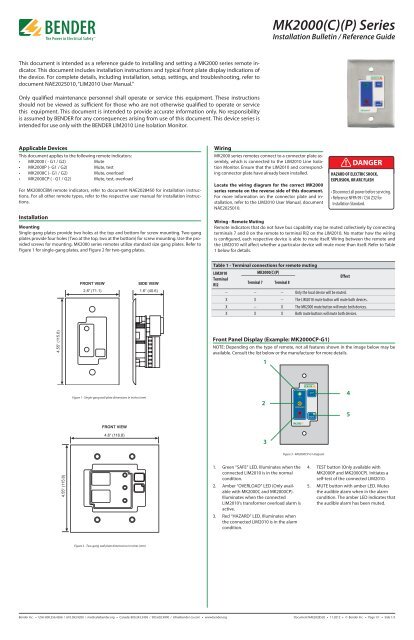
Front Panel Display (Example: <strong>MK2000</strong>CP-G1)<br />
NOTE: Depending on the type of remote, not all features shown in the image below may be<br />
available. Consult the list below or the manufacturer for more details.<br />
1<br />
1. Green “SAFE” LED. Illuminates when the<br />
connected LIM2010 is in the normal<br />
condition.<br />
2. Amber “OVERLOAD” LED (Only available<br />
with <strong>MK2000</strong>C and <strong>MK2000</strong>CP).<br />
Illuminates when the connected<br />
LIM2010’s transformer overload alarm is<br />
active.<br />
3. Red “HAZARD” LED. Illuminates when<br />
the connected LIM2010 is in the alarm<br />
condition.<br />
2<br />
3<br />
P<br />
Figure 3 - <strong>MK2000</strong>CP-G1 diagram<br />
! DANGER<br />
HAZARD OF ELECTRIC SHOCK,<br />
EXPLOSION, OR ARC FLASH<br />
• Disconnect all power before servicing.<br />
• Reference NFPA 99 / CSA Z32 for<br />
Installation Standard.<br />
Wiring - Remote Muting<br />
Remote indicators that do not have bus capability may be muted collectively by connecting<br />
terminals 7 and 8 on the remote to terminal RI2 on the LIM2010. No matter how the wiring<br />
is configured, each respective device is able to mute itself. Wiring between the remote and<br />
the LIM2010 will affect whether a particular device will mute more than itself. Refer to Table<br />
1 below for details.<br />
4. TEST button (Only available with<br />
<strong>MK2000</strong>P and <strong>MK2000</strong>CP). Initiates a<br />
self-test of the connected LIM2010.<br />
5. MUTE button with amber LED. Mutes<br />
the audible alarm when in the alarm<br />
condition. The amber LED indicates that<br />
the audible alarm has been muted.<br />
Document NAE2028520 • 11.2012 • © <strong>Bender</strong> Inc. • Page 1/1 • Side 1/2<br />
4<br />
5
Figure 4 - Wiring, <strong>MK2000</strong><br />
L1<br />
L2<br />
12VDC CM<br />
A<br />
B<br />
RI1<br />
K1/NC<br />
K1/COM<br />
K1/NO<br />
SAFE<br />
HAZARD<br />
RI2<br />
GND2<br />
LIMGND<br />
TEST<br />
1S1<br />
Z1/M+<br />
1S2<br />
Z2/M-<br />
K2/COM<br />
K2/NC<br />
K2/NO<br />
CP-LIM2010<br />
Connector Plate<br />
Figure 5 - Wiring, <strong>MK2000</strong>C<br />
L1<br />
L2<br />
12VDC CM<br />
A<br />
B<br />
RI1<br />
K1/NC<br />
K1/COM<br />
K1/NO<br />
SAFE<br />
HAZARD<br />
RI2<br />
GND2<br />
LIMGND<br />
TEST<br />
1S1<br />
Z1/M+<br />
1S2<br />
Z2/M-<br />
K2/COM<br />
K2/NC<br />
K2/NO<br />
CP-LIM2010<br />
Connector Plate<br />
L1 to<br />
load center<br />
Figure 6 - Wiring, <strong>MK2000</strong>P<br />
L1<br />
L2<br />
12VDC CM<br />
A<br />
B<br />
RI1<br />
K1/NC<br />
K1/COM<br />
K1/NO<br />
SAFE<br />
HAZARD<br />
RI2<br />
GND2<br />
LIMGND<br />
TEST<br />
1S1<br />
Z1/M+<br />
1S2<br />
Z2/M-<br />
K2/COM<br />
K2/NC<br />
K2/NO<br />
CP-LIM2010<br />
Connector Plate<br />
T M<br />
STW3 / STW4<br />
SAFE<br />
HAZARD<br />
To<br />
load center<br />
SAFE<br />
HAZARD<br />
To<br />
load center<br />
SAFE<br />
HAZARD<br />
L1 from<br />
transformer<br />
secondary<br />
To<br />
load center<br />
<strong>Bender</strong> Inc. • USA: 800.356.4266 / 610.383.9200 / medical@bender.org • Canada: 800.243.2438 / 905.602.9990 / info@bender-ca.com • www.bender.org<br />
MUTE<br />
TEST<br />
RESET<br />
MENU<br />
To panel<br />
ground bus<br />
ESC<br />
LIM2010<br />
MUTE<br />
TEST<br />
RESET<br />
MENU<br />
To panel<br />
ground bus<br />
ESC<br />
LIM2010<br />
MUTE<br />
TEST<br />
RESET<br />
MENU<br />
To panel<br />
ground bus<br />
ESC<br />
LIM2010<br />
<strong>MK2000</strong><br />
<strong>MK2000</strong>C<br />
<strong>MK2000</strong>P<br />
Figure 7 - Wiring, <strong>MK2000</strong>CP<br />
L1<br />
L2<br />
12VDC CM<br />
A<br />
B<br />
RI1<br />
K1/NC<br />
K1/COM<br />
K1/NO<br />
SAFE<br />
HAZARD<br />
RI2<br />
GND2<br />
LIMGND<br />
TEST<br />
1S1<br />
Z1/M+<br />
1S2<br />
Z2/M-<br />
K2/COM<br />
K2/NC<br />
K2/NO<br />
CP-LIM2010<br />
Connector Plate<br />
L1 to<br />
load center<br />
<strong>MK2000</strong>(C)(P) <strong>Series</strong><br />
Installation Bulletin / Reference Guide<br />
STW3 / STW4<br />
SAFE<br />
HAZARD<br />
To<br />
load center<br />
L1 from<br />
transformer<br />
secondary<br />
Technical Data<br />
Operating voltage 12V DC or 12V AC<br />
Max. current 50 mA<br />
(<strong>MK2000</strong>CBM 100 mA)<br />
Operation class<br />
Ambient temperature<br />
continuous operation<br />
when operating +32º F to +122º F<br />
0º C to +50º<br />
when stored -13º F to +158º F<br />
-25º C to +70º C<br />
Connection screw terminal block<br />
Conductor size AWG 30…12<br />
Tightening torque 5…7 lb-in.<br />
Mounting<br />
Weight<br />
by screws<br />
<strong>MK2000</strong>-G1 / <strong>MK2000</strong>P-G1 / <strong>MK2000</strong>C-G1 / <strong>MK2000</strong>CP-G1 0.25 lb<br />
<strong>MK2000</strong>-G2 / <strong>MK2000</strong>CBM 0.32 lb<br />
MUTE<br />
TEST<br />
RESET<br />
MENU<br />
To panel<br />
ground bus<br />
ESC<br />
LIM2010<br />
<strong>MK2000</strong>CP<br />
Figure 8 - Wiring, <strong>MK2000</strong>CBM<br />
Refer to <strong>MK2000</strong>CBM installation bulletin, document NAE2028450 for instructions and wiring<br />
diagram for installing an <strong>MK2000</strong>CBM remote indicator.<br />
Document NAE2028520 • 11.2012 • © <strong>Bender</strong> Inc. • Page 1/1 • Side 2/2


