Designing 100kHz, flyback transformers for input ... - Rale Engineering
Designing 100kHz, flyback transformers for input ... - Rale Engineering
Designing 100kHz, flyback transformers for input ... - Rale Engineering

You also want an ePaper? Increase the reach of your titles
YUMPU automatically turns print PDFs into web optimized ePapers that Google loves.
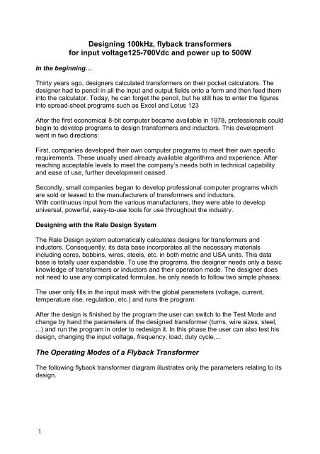
In the beginning…<br />
1<br />
<strong>Designing</strong> <strong>100kHz</strong>, <strong>flyback</strong> <strong>trans<strong>for</strong>mers</strong><br />
<strong>for</strong> <strong>input</strong> voltage125-700Vdc and power up to 500W<br />
Thirty years ago, designers calculated <strong>trans<strong>for</strong>mers</strong> on their pocket calculators. The<br />
designer had to pencil in all the <strong>input</strong> and output fields onto a <strong>for</strong>m and then feed them<br />
into the calculator. Today, he can <strong>for</strong>get the pencil, but he still has to enter the figures<br />
into spread-sheet programs such as Excel and Lotus 123<br />
After the first economical 8-bit computer became available in 1978, professionals could<br />
begin to develop programs to design <strong>trans<strong>for</strong>mers</strong> and inductors. This development<br />
went in two directions:<br />
First, companies developed their own computer programs to meet their own specific<br />
requirements. These usually used already available algorithms and experience. After<br />
reaching acceptable levels to meet the company’s needs both in technical capability<br />
and ease of use, further development ceased.<br />
Secondly, small companies began to develop professional computer programs which<br />
are sold or leased to the manufacturers of <strong>trans<strong>for</strong>mers</strong> and inductors.<br />
With continuous <strong>input</strong> from the various manufacturers, they were able to develop<br />
universal, powerful, easy-to-use tools <strong>for</strong> use throughout the industry.<br />
<strong>Designing</strong> with the <strong>Rale</strong> Design System<br />
The <strong>Rale</strong> Design system automatically calculates designs <strong>for</strong> <strong>trans<strong>for</strong>mers</strong> and<br />
inductors. Consequently, its data base incorporates all the necessary materials<br />
including cores, bobbins, wires, steels, etc. in both metric and USA units. This data<br />
base is totally user expandable. To use the programs, the designer needs only a basic<br />
knowledge of <strong>trans<strong>for</strong>mers</strong> or inductors and their operation mode. The designer does<br />
not need to use any complicated <strong>for</strong>mulas, he only needs to follow two simple phases:<br />
The user only fills in the <strong>input</strong> mask with the global parameters (voltage, current,<br />
temperature rise, regulation, etc.) and runs the program.<br />
After the design is finished by the program the user can switch to the Test Mode and<br />
change by hand the parameters of the designed trans<strong>for</strong>mer (turns, wire sizes, steel,<br />
...) and run the program in order to redesign it. In this phase the user can also test his<br />
design, changing the <strong>input</strong> voltage, frequency, load, duty cycle,...<br />
The Operating Modes of a Flyback Trans<strong>for</strong>mer<br />
The following <strong>flyback</strong> trans<strong>for</strong>mer diagram illustrates only the parameters relating to its<br />
design.
With a <strong>flyback</strong> trans<strong>for</strong>mer, the distinction is drawn between two modes of operation:<br />
Mode with continuous secondary current ( Fig. 1, t3=0).<br />
Mode with intermittent DC secondary current (Fig. 2, t3>0).<br />
Continuous mode (Fig.1)<br />
In this mode, secondary current ripple is less than 100%:<br />
3<br />
Ripple = 100* (Ismax-Ismin)/(Ismax+Ismin) =(Bmax-Bmin)/(Bmax+Bmin) < 100<br />
In the <strong>flyback</strong> trans<strong>for</strong>mer’s continuous mode, the output voltage is "impressed" <strong>for</strong><br />
practical purposes, and is not greatly dependent upon load. Because the variation of<br />
the duty cycle is not directly proportional to the variation of the <strong>input</strong> voltage, this mode<br />
is preferred <strong>for</strong> a wide range of the <strong>input</strong> voltages (min. 3:1). Secondly, the <strong>flyback</strong><br />
trans<strong>for</strong>mer is larger with less ripple in the primary current. For that reason, the choice<br />
of ripple (10% to 100%) of the secondary current has to be harmonized between the<br />
trans<strong>for</strong>mer manufacturer and the electronics engineer.<br />
Intermittent mode (Fig.2)<br />
If the range of the <strong>input</strong> is not too wide (max. 3:1) then this is the most common<br />
operation mode because the <strong>flyback</strong> trans<strong>for</strong>mer is smaller than in the continuous<br />
operation mode:<br />
t1=t2 at minimal <strong>input</strong> voltage<br />
Ripple => 100%.<br />
Input only relevant to the design of a <strong>flyback</strong><br />
Criterion <strong>for</strong> design<br />
Normally, high-frequency <strong>trans<strong>for</strong>mers</strong> have very low regulation and are designed<br />
according to the prescribed temperature rise. Since these <strong>trans<strong>for</strong>mers</strong> are<br />
manufactured almost exclusively using ferrite, the optimum operating temperature is<br />
around 100°C.<br />
Bobbin<br />
In order to protect the transistors, high-frequency <strong>trans<strong>for</strong>mers</strong> should be manufactured<br />
<strong>for</strong> low leaking reactance , with single-section bobbin units. For this reason, they often<br />
require bifilar or interleaved windings.<br />
Ferrite, Induction and Temperature rise<br />
Since the optimum operating temperature of ferrite <strong>for</strong> high-frequency <strong>trans<strong>for</strong>mers</strong> is<br />
around 100°C and their ambient temperature is 40°C , our design assumption must be<br />
<strong>for</strong> a temperature rise of 60°K. The program calculates both the active and the reactive<br />
core losses by hypothesizing the ferrite type, the frequency, the <strong>for</strong>m of <strong>input</strong> voltage,<br />
induction and core temperature. The induction should be selected so that the<br />
trans<strong>for</strong>mer does not saturate at minimum <strong>input</strong> voltage, maximum duty cycle and<br />
maximum core temperature. If the core losses in relation to temperature rise are not<br />
economically acceptable, then the computer program will optimize or reduce the AC-
component (the ripple of the <strong>input</strong> current) of the induction automatically. But this<br />
indicates that the selected ferrite quality is not optimal.<br />
Copper additional losses<br />
With a high-frequency trans<strong>for</strong>mer, the distinctions are drawn between the following<br />
additional losses in a winding, over and above the dc-current losses:<br />
1. Eddy current losses<br />
2. Skin effect losses<br />
3. Proximity effect losses<br />
4. Losses due to circulating currents through the parallel-connected wires.<br />
Proximity losses are smaller in the case of a winding that takes up only 30-60% of the<br />
available winding space. For that reason, one should always set the <strong>input</strong> <strong>for</strong> the<br />
Space between 0.3 and 0.6 <strong>for</strong> purposes of automatic core selection by the program.<br />
The <strong>input</strong> <strong>for</strong> Rac/Rdc will limit the extent of additional losses. The computer program<br />
selects a high enough number of parallel-connected wires <strong>for</strong> the eddy current losses<br />
and skin effect losses to fall short of the prescribed value <strong>for</strong> Rac/Rdc. For that reason,<br />
the <strong>input</strong> <strong>for</strong> Rac/Rdc is also used <strong>for</strong> monitoring parallel-connected wires. The value is<br />
normally set between 1.25 and 3.<br />
Losses of circulating currents through the parallel-connected wires are not calculated.<br />
It is assumed that these additional losses have been eliminated by suitable design<br />
precautions. In particular, it should be ensured, <strong>for</strong> a given litz, that the twisting <strong>for</strong> the<br />
winding maintains the same position at the <strong>input</strong> and at the output of the winding <strong>for</strong><br />
any given winding.<br />
Duty cycle at minimal <strong>input</strong> voltage<br />
4
The duty cycle q is defined as follows:<br />
A <strong>flyback</strong> trans<strong>for</strong>mer with an automatic controller of output voltage and current ripple<br />
less than 100% is normally designed with the following parameters:<br />
"Nominal" <strong>input</strong> voltage Upnom= (Upmin*Upmax)1/2 = (125*700) 1/2= 296V. At this <strong>input</strong><br />
voltage the duty cycle qnom will be 0.5.<br />
This <strong>flyback</strong> trans<strong>for</strong>mer has to be designed at the <strong>input</strong> voltage Upmin = 125V. At this<br />
<strong>input</strong> voltage the duty cycle will be:<br />
qmax = Unom/(Umin + Unom) = 296/(125+296) = 0.7.<br />
Th duty cycle at the <strong>input</strong> voltage Upmax = 700V will be:<br />
qmin = Upnom/(Upmax+Upnom) = 296/(700+296) = 0.3<br />
Ripple of the <strong>input</strong> current at the minimal <strong>input</strong> voltage = 17%<br />
In order to have the ripple smaller than 100% at the maximal <strong>input</strong> voltage, you have to<br />
prescribe the ripple at the minimal <strong>input</strong> voltage as follows:<br />
Ripplemin = Ripplemax *(Upmin*qmax/Upmax/qmin)^2 = 100*(0.7*125/750/0.3)^2 < 17%<br />
5
Procedure to design a 200W <strong>flyback</strong> trans<strong>for</strong>mer<br />
Normally the user loads the standard <strong>input</strong> file <strong>for</strong> the <strong>flyback</strong> trans<strong>for</strong>mer and fills in<br />
the <strong>input</strong> mask in accordance with the discussion above. Note that all other parameters<br />
(such as chassis, insulation, case, impregnation,…) are generally relevant to the<br />
trans<strong>for</strong>mer design and will not be discussed:<br />
Input voltage : U(V) = 125V<br />
Duty cycle : Formfactor = 0.7<br />
Ripple of the primary current (induction) : dI/Io = 17%<br />
Output DC-voltage : Voltage = 2 x 24V<br />
Output DC-current ; Current = 2 x 4A<br />
Ambient temperature : Amb. Temp. = 40°C<br />
Temperature rise : Temp. rise = 60°K<br />
Induction = 0.275T<br />
6
Single-section bobbin with the primary between 2 secondary : Bobbin = 11<br />
Max. Build 50%: Space = 0.5<br />
Factor <strong>for</strong> additional Cu-losses : Rac/Rdc = 3<br />
If the core size is not prescribed by the user the <strong>input</strong> field Selection is set at 0. This<br />
means that the program should search <strong>for</strong> a suitable core <strong>for</strong> this application from your<br />
selected core family. In the system <strong>for</strong> automatic selection of the core from your<br />
prescribed core family, the program will offer you an adequately sized core <strong>for</strong> your<br />
application.<br />
On completion of the design work, the following design data will be available, which<br />
7
can be saved and/or printed on 3 pages:<br />
8
Checking the design<br />
However, there are two parameters, which relate exclusively to the <strong>flyback</strong> trans<strong>for</strong>mer:<br />
primary winding inductance (1.12 mH) and the gap (2x0.014") <strong>for</strong> calibration of the<br />
primary winding inductance at the nominal frequency.<br />
The winding filling factor :44%
The maximum temperature of the windings is 40°C+57°K = 97°C < 115°C.<br />
The number of parallel-connected wires (litz) <strong>for</strong> the secondary only is<br />
30 x WG 29. A copper foil can replace this litz. The foil thickness should correspond to<br />
the wire diameter of the litz (11.3 mill or less). The foil width should be matched to the<br />
width of the bobbin. The number of foils connected in parallel is determined in<br />
accordance with the following illustration.<br />
Using the Test Mode<br />
If the design data is not satisfactory, then you can access the test mode, modify the<br />
designed trans<strong>for</strong>mer manually (turns, wire size, steel, <strong>input</strong> voltage, load, duty<br />
cycle,…) and redesign the trans<strong>for</strong>mer by that means. The following output mask in the<br />
test mode shows the results by checking the output voltage <strong>for</strong> the maximal <strong>input</strong><br />
voltage of 700V and the duty cycle of 0.3: Uin = 700/125 = 5.6.<br />
11
The following table shows the summary of the most important parameters, calculated<br />
by the program in the test mode. Note that the duty cycle (q) was changed in order to<br />
get the nominal <strong>input</strong> voltage that a voltage controller would give.<br />
12<br />
Ui<br />
V<br />
Iprms<br />
A<br />
2xIsrms<br />
A<br />
2xUodc<br />
V<br />
2xIodc<br />
A<br />
Pcu<br />
W<br />
Pfe<br />
W<br />
Q Ripple<br />
%<br />
DTcu<br />
°K<br />
125 1.87 7.22 23.6 3.93 4.62 0.55 0.7 17.7 57.4<br />
296 1.01 5.98 24.1 4.03 2.50 1.7 0.5 47.4 46.5<br />
700 0.62 5.58 24.5 4.11 1.28 3.53 0.3 93 49.4<br />
In order to get the constant total losses in the whole range of the <strong>input</strong> voltage, select<br />
the ferrite and the operation frequency at the nominal <strong>input</strong> voltage so that you get<br />
approximately Pfe = Pcu<br />
Technical specification common <strong>for</strong> all designs<br />
All <strong>flyback</strong> <strong>trans<strong>for</strong>mers</strong> in the following table were calculated under the same<br />
conditions:<br />
Input voltage : 125Vdc - 700Vdc<br />
Output voltages : 2 x 24Vdc<br />
Frequency : <strong>100kHz</strong><br />
Duty cycle : 0.7 at the <strong>input</strong> voltage 125V<br />
Ripple of the induction : 17% at the <strong>input</strong> voltage 125Vdc<br />
Peak induction : 0.25-0.28T<br />
Build of the windings : approx. 50%
Ambient temperature : 40°C<br />
Temperature rise : 60°K<br />
Core family and ferrite : ETD, N27 or better<br />
Order of the windings : Primary between both secondary<br />
The parameters of the designs are core size, output power and eddy current losses<br />
(Rac/Rdc)<br />
13<br />
/ Primary Secondary<br />
Core Rac/Rdc Power<br />
W<br />
ETD<br />
19<br />
Inductance<br />
mH<br />
Turns<br />
Parallel<br />
x Wire<br />
Gauge<br />
Turns<br />
Parallel<br />
x Wire<br />
Gauge<br />
1.3 23 8.8 242 1x37 2x5 1x29<br />
ETD24 2 38 5.54 185 1x33 2x16 1x25<br />
1.20 48 4.47 1x33 10x34<br />
ETD29 2.9 60 3.34 142 1x30 2x12 1x22<br />
1.9 75 2.8 1x29 9x30<br />
1.20 85 2.43 2x32 40x36<br />
ETD34 1.65 95 2.26 117 1x28 2x10 30x32<br />
1.25 110 1.91 3x33 65x36<br />
ETD39 2,75 125 1.73 94 1x25 2x8 22x29<br />
1.90 145 1.46 2x29 50x32<br />
1.25 177 1.19 6x33 140x33<br />
ETD44 1.80 230 0.89 71 5x29 2x6 90x33<br />
1.25 280 0.75 15x34 300x38<br />
ETD49 2.00 330 0.65 59 10x30 2x5 200x34<br />
1.20 423 0.50 40x36 750x40
About <strong>Designing</strong> of Flyback Trans<strong>for</strong>mers<br />
About <strong>Rale</strong> Input<br />
In order to design a <strong>flyback</strong> trans<strong>for</strong>mer with the <strong>Rale</strong> Design Software you need the following <strong>input</strong>s:<br />
14<br />
1. Min. <strong>input</strong> voltage and the duty cycle at this voltage<br />
2. Dc-output voltages and dc-output currents<br />
3. The ripple of the <strong>input</strong> current (induction)<br />
4. Frequency<br />
In the following Figure are 2 typical operation modes:<br />
• Continuous mod Bmin>0<br />
• Discontinuous mode Bmin=0
User Input<br />
Some of customers use other <strong>input</strong>s <strong>for</strong> designing of a <strong>flyback</strong>. Here are some typical cases<br />
Inductance of the primary winding<br />
You know:<br />
15<br />
1. Min. <strong>input</strong> voltage and the duty cycle at this voltage<br />
2. DC-output voltages and dc-output currents (output power)<br />
3. Inductance of the primary winding<br />
4. Frequency<br />
Then you need to calculate the ripple of the primary<br />
Pout = L x (Imax^2-Imin^2) x f / 2 = L x (Imax+Imin) x (Imax-Imin) x f /2<br />
Where:<br />
Using:<br />
• Pout Output power in W<br />
• L Inductance in H<br />
• F Frequency in Hz<br />
• Imax Max. primary current (peak)<br />
• Imin Min. primary current<br />
Ripple%= 100 x (Imax-Imin)/(Imax+Imin)<br />
Iav = (Imax+Imin)/2<br />
Pout = Uin x Iav x q<br />
We can calculate:<br />
Pout = 2 x L x Iav^2 x (Ripple%/100) x f<br />
or<br />
Ripple% = 100 x Uin^2 x q^2 / L / Pout / f / 2 (
16<br />
Ration of the primary and secondary turns in continuous operation mode<br />
You know:<br />
1. Min. <strong>input</strong> voltage<br />
2. DC-output voltages and dc-output currents (output power)<br />
3. Inductance of the primary winding<br />
4. Frequency<br />
5. Ratio of the primary and secondary turns (T1/T2)<br />
6. Continuous operation mode (s=p, Bmin>0, see Figure)<br />
Now you need to calculate the duty cycle (Formfactor) and the <strong>input</strong> dIo/I:<br />
(Uin x q) / (Uout x s) = (T1/T2)<br />
s= p = 1 - q<br />
q = A/(1+A)<br />
and<br />
Formfactor = 1 / 2 / q<br />
Ripple% = 100 x Uin^2 x q^2 / L / Pout / f / 2 (
dIo/I = 100 x (1- q) / s<br />
Formfactor = 1 / 2 / q<br />
Home<br />
17