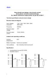
non-inherently short-circuit proof safety transformer for halogen ...
non-inherently short-circuit proof safety transformer for halogen ...
non-inherently short-circuit proof safety transformer for halogen ...

You also want an ePaper? Increase the reach of your titles
YUMPU automatically turns print PDFs into web optimized ePapers that Google loves.
1<br />
How do we design<br />
a 60VA - <strong>non</strong>-<strong>inherently</strong> <strong>short</strong>-<strong>circuit</strong> <strong>proof</strong> <strong>safety</strong><br />
<strong>trans<strong>for</strong>mer</strong><br />
<strong>for</strong> <strong>halogen</strong> lamps in accordance with IEC 61558,<br />
protected by a thermal cutout ?<br />
Technical specification relevant only to design<br />
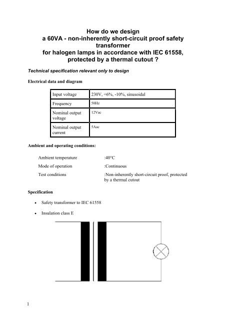
Electrical data and diagram<br />
Input voltage 230V, +6%, -10%, sinusoidal<br />
Frequency<br />
Nominal output<br />
voltage<br />
Nominal output<br />
current<br />
50Hz<br />
12Vac<br />
5Aac<br />
Ambient and operating conditions:<br />
Ambient temperature :40°C<br />
Mode of operation :Continuous<br />
Test conditions :Non-<strong>inherently</strong> <strong>short</strong>-<strong>circuit</strong> <strong>proof</strong>, protected<br />
by a thermal cutout<br />
Specification<br />
• Safety <strong>trans<strong>for</strong>mer</strong> to IEC 61558<br />
• Insulation class E
Design criteria<br />
IEC 6155<br />
A <strong>non</strong>-<strong>inherently</strong> <strong>short</strong>-<strong>circuit</strong> <strong>proof</strong> <strong>trans<strong>for</strong>mer</strong> as per IEC 61558 is equipped with a cutout<br />
to protect against <strong>short</strong>-<strong>circuit</strong> and overload. In this case, the <strong>trans<strong>for</strong>mer</strong> should be equipped<br />
with a thermal cutout:<br />
The procedure <strong>for</strong> testing is prescribed as per paragraphs 14.2, 15.3.1 and 15.3.5 as follows:<br />
2<br />
1. Firstly, the <strong>trans<strong>for</strong>mer</strong> as per paragraph 14.2 is loaded with nominal resistance and at<br />
1.06 x the nominal input voltage until permanent operating temperature is achieved.<br />
In this context, the temperature of the windings must not exceed the value of θ<br />
nominal.<br />
2. Next, all output windings are <strong>short</strong>-<strong>circuit</strong>ed. At 1.06 x the nominal input voltage, the<br />
integral thermal cutout should actuate, be<strong>for</strong>e the temperature reaches the level of θ<br />
max as per the following table.<br />
3. Finally, the <strong>trans<strong>for</strong>mer</strong> is loaded at 0.95 x the value of the lowest current, which<br />
causes actuation of the thermal cutout, until attainment of continuous operating<br />
temperature. In this context, the thermal cutout should not actuate and the<br />
temperature should not exceed the value of θ max.<br />
Insulation class A E B F H<br />
Max. winding<br />
temperature in test θ<br />
max (° C)<br />
Max. case temperature<br />
in test (° C)<br />
Max. winding<br />
temperature in nominal<br />
operation mode θ<br />
nominal (° C)<br />
Max. case temperature<br />
in nominal operation<br />
mode (° C)<br />
200 215 225 240 260<br />
105 105 105 105 105<br />
100 115 120 140 165<br />
80 80 80 80 80<br />
Insulation class<br />
Maximal winding temperature in nominal operation mode = 115°C<br />
Maximal winding temperature in test mode = 215°C<br />
Insulation class E is prescribed.<br />
Thermal cutout<br />
The thermal cutout (temperature-operated cutout, PTC, ..) is located in the primary windings.<br />
We choose an actuation temperature of between θ nominal and θ max. In the case of a<br />
<strong>trans<strong>for</strong>mer</strong> in a mobile installation, in which context the surface temperature of the case<br />
must not exceed 80°C, the insulation class of the <strong>trans<strong>for</strong>mer</strong> A and the actuation<br />
temperature of the thermal cutout are selected lower than θ nominal.
Let’s choose a thermal cutout actuation temperature of between θ nominal and θ max.<br />
Sheet quality, core <strong>for</strong>m and winding technology<br />
For pricing reasons, <strong>trans<strong>for</strong>mer</strong>s <strong>for</strong> <strong>halogen</strong> lamps are equipped with core quality 5.3W/kg<br />
and 1.5T, and 50Hz. The distinction is drawn between two basic specifications:<br />
3<br />
• With a bobbin which has a cover or is potted in the case.<br />
• Without a bobbin, "dry" pressed, with a cover.<br />
In this specification, we use small cut <strong>for</strong>ms with high coating thickness. Windings<br />
are enveloped in a "hose" and pressed into the winding space of the <strong>trans<strong>for</strong>mer</strong>.<br />
The core construction looks like that of a choke or of a welded <strong>trans<strong>for</strong>mer</strong>. The<br />
result is a gap which is suitable <strong>for</strong> operation with a dimmer which is envisaged <strong>for</strong><br />
the brightness control.<br />
Let’s choose the <strong>non</strong>-annealed, cold-rolled core quality of 5.3W/kg <strong>for</strong> 1.5T, 50Hz, 0.5mm<br />
thick, sheet <strong>for</strong>m EI 42/125, without holes in the corners, with pressed windings.<br />
Impregnation<br />
Normally, a double-chamber bobbin unit is made with a cover such that the <strong>trans<strong>for</strong>mer</strong> can<br />
be manufactured "dry".<br />
Our <strong>trans<strong>for</strong>mer</strong> is manufactured without impregnation.<br />
Induction<br />
These <strong>trans<strong>for</strong>mer</strong>s are designed with an induction of between 1.3T and 1.5T in nominal<br />
operating mode.<br />
Nominal output voltage<br />
Normally, the nominal output voltage of <strong>trans<strong>for</strong>mer</strong>s <strong>for</strong> <strong>halogen</strong> lamps is 5% lower than<br />
the lamps' nominal voltage.<br />
Let’s calculate our design with 11.5 V nominal output voltage.<br />
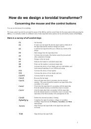
Procedure <strong>for</strong> design<br />
1. If you are not yet familiar with the Rale Design Software, then you should read the<br />
text: "How do I design a small <strong>trans<strong>for</strong>mer</strong>?". You should keep a copy of this text<br />
within your reach whenever per<strong>for</strong>ming design operations.<br />
2. Fill in the input mask as follows. If you need any help, press function key F1. There<br />
is extensive description <strong>for</strong> each input field.
4<br />
3.<br />
4. Select the core family of core <strong>for</strong>m EI 42. Copy any EI 42 onto the clipboard.<br />
5.<br />
6. Change the name and the coating thickness. You also have to set up the "bobbin unit"<br />
<strong>for</strong> windings which are enveloped by a "hose".<br />
7.<br />
8. Click on OK.<br />
9. Save your input data file. In this design example, the input data has been saved in<br />
input data file CAL0004E.TK1. This input data file was supplied together with this<br />
document. Copy it into the directory where the RALE Demo program is installed.<br />
10. Make a connection with your Rale design server.<br />
11. Load up your input data file and start designing.<br />
12. After completion of your design work, the following design data is available, that can<br />
be printed on three pages:
5<br />
13.
9<br />
14. This is followed by monitoring of the design data.<br />
• We start by checking the max winding temperature in nominal operation mode =<br />
ambient temperature + dTprim in nominal operation mode= 40+72 =112 < 115°C<br />
• Next, we check the winding data and the filling factor (73%
10<br />
1. After completing our design work, we can print out the design data on-line, or save it<br />
on the local PC and print it out off-line. The output data file from this design example<br />
CAL0004E.TK2 is supplied together with this document. Copy it into the directory in<br />
which the Rale demo program is installed.<br />
Tips & Tricks<br />
The <strong>trans<strong>for</strong>mer</strong> is too full<br />
This is often the case if we select our own core. Suppose we want to use the core <strong>for</strong> 100VA,<br />
<strong>for</strong> example.<br />
• Increase the overtemperature to the permitted value.<br />
• Increase the induction. Ensure that the idling temperature does not exceed the<br />
permitted value <strong>for</strong> the insulation class.<br />
The <strong>trans<strong>for</strong>mer</strong> is relatively empty<br />
This is often the case if we select our own core. Suppose we want to use the core <strong>for</strong> 100VA,<br />
f or example.<br />
or<br />
• Select a smaller core<br />
• Reduce the temperature rise<br />
• or<br />
• Reduce the induction.<br />
The bobbin unit chambers are filled asymmetrically, e.g. 70% : 90%.
Manually change the wire thickness in the test program:<br />
11<br />
• Select the next higher wire thickness in the chamber which is less full.<br />
• Select the next lower wire thickness in the chamber, which is more full.<br />
• Correct the number of windings of the secondary, in order to arrive at the desired<br />
output voltage.<br />
Nominal operating data<br />
This <strong>trans<strong>for</strong>mer</strong> was designed <strong>for</strong> 6% over-voltage. In order to arrive at the nominal data <strong>for</strong><br />
this <strong>trans<strong>for</strong>mer</strong> design, test the designed <strong>trans<strong>for</strong>mer</strong> with the nominal input voltage in the<br />
test program. (Uin = 1 ).<br />
Temperature in nominal operation mode is too high<br />
• Reduce the temperature rise and increase the induction.<br />
• Set a better core quality.<br />
• Increase the cooling surface area. Choose a larger case. The color of the case should<br />
be dark.<br />
Is the idling current too high?<br />
The idling current is not a criterion <strong>for</strong> design. The idling temperature must not exceed the<br />
permitted limit.<br />
The combined fuse<br />
In the event of poor thermal connection between the thermal cutout and the protected<br />
winding, a further fine fuse is employed to prevent <strong>short</strong>-<strong>circuit</strong>. With this combined fuse,<br />
the thermal cutout provides protection against overload and the fine fuse provides protection<br />
against <strong>short</strong>-<strong>circuit</strong>.<br />
Home