How should one design a 50kHz, 1200VA transformer as per IEC ...
How should one design a 50kHz, 1200VA transformer as per IEC ...
How should one design a 50kHz, 1200VA transformer as per IEC ...

You also want an ePaper? Increase the reach of your titles
YUMPU automatically turns print PDFs into web optimized ePapers that Google loves.
1<br />
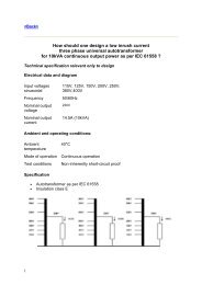
<strong>How</strong> <strong>should</strong> <strong>one</strong> <strong>design</strong> a <strong>50kHz</strong>, <strong>1200VA</strong> <strong>transformer</strong><br />
<strong>as</strong> <strong>per</strong> <strong>IEC</strong> 61558 ?<br />
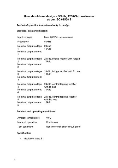
Technical specification relevant only to <strong>design</strong><br />
Electrical data and diagram<br />
Input voltages Max. 280Vac, square-wave<br />
Frequency <strong>50kHz</strong><br />
Nominal output voltage<br />
1<br />
Nominal output current<br />
1<br />
Nominal output voltage<br />
2<br />
Nominal output current<br />
2<br />
Nominal output voltage<br />
3<br />
Nominal output current<br />
3<br />
Nominal output voltage<br />
4<br />
Nominal output current<br />
4<br />
Nominal output voltage<br />
5<br />
Nominal output current<br />
5<br />
24Vac<br />
10Aac<br />
Ambient and o<strong>per</strong>ating conditions:<br />
Ambient tem<strong>per</strong>ature 40°C<br />
Mode of o<strong>per</strong>ation Continuous<br />
24Vdc, bridge rectifier with R load<br />
10Adc<br />
24Vdc, bridge rectifier with RL load<br />
10Adc<br />
24Vdc, central tapping rectifier<br />
with R load<br />
10Adc<br />
24Vdc, central tapping rectifier<br />
with RL load<br />
10Adc<br />
Test conditions Non inherently short-circuit proof<br />
Specification<br />
• Insulation cl<strong>as</strong>s E
2<br />
Criteria for <strong>design</strong><br />
<strong>IEC</strong> 61558<br />
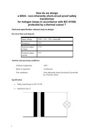
A high-frequency <strong>transformer</strong> with non inherently short-circuit proof <strong>as</strong> <strong>per</strong> <strong>IEC</strong><br />
61558 is equipped with a safety. Very often we arrive at a combined protection<br />
solution consisting of a thermal cutout in the <strong>transformer</strong> and cut-out electronics<br />
in the cycled mains power unit to protect against overload and short-circuit. For<br />
this re<strong>as</strong>on, short-circuit and overload are not <strong>design</strong> criteria. The criterion for<br />
<strong>design</strong> with regard to <strong>IEC</strong> 61558 is only tem<strong>per</strong>ature θ nominal.<br />
Insulation cl<strong>as</strong>s A E B F H<br />
Max winding<br />
tem<strong>per</strong>ature in test θ<br />
max (° C)<br />
Max winding<br />
tem<strong>per</strong>ature in<br />
nominal o<strong>per</strong>ating<br />
mode θ nominal (°<br />
C)<br />
200 215 225 240 260<br />
100 115 120 140 165<br />
Insulation cl<strong>as</strong>s<br />
Max winding tem<strong>per</strong>ature in nominal o<strong>per</strong>ating mode = 115°C<br />
Max winding tem<strong>per</strong>ature in test mode = 215°C
3<br />
Insulation cl<strong>as</strong>s E is prescribed.<br />
Criterion for <strong>design</strong><br />
Normally, high-frequency <strong>transformer</strong>s have very low regulation and are<br />
<strong>design</strong>ed according to the prescribed tem<strong>per</strong>ature rise.<br />
Since these <strong>transformer</strong>s are manufactured almost exclusively using ferrite, the<br />
optimum o<strong>per</strong>ating tem<strong>per</strong>ature is around 100°C.<br />
Bobbin unit<br />
In order to protect the transistors, high-frequency <strong>transformer</strong>s <strong>should</strong> be<br />
manufactured for low scatter, with single-chamber bobbin units. For this re<strong>as</strong>on,<br />
we very often arrive at dual-wire or interleaved windings.<br />
Ferrite quality<br />
Since the optimum o<strong>per</strong>ating tem<strong>per</strong>ature of ferrite for high-frequency<br />
<strong>transformer</strong>s over 100VA is around 100°C and their ambient tem<strong>per</strong>ature is<br />
between 40°C and 70°C, our <strong>design</strong> <strong>as</strong>sumption must be for an tem<strong>per</strong>ature rise<br />
of between 30°K and 60°K. If the core losses in relation to tem<strong>per</strong>ature rise are<br />
not economically acceptable, then the computer program will optimise or reduce<br />
induction automatically. But this does indicate that the selected ferrite quality is<br />
not optimized.<br />
Induction and ferrite quality<br />
High-frequency <strong>transformer</strong>s are equipped almost exclusively with ferrite. The<br />
program calculates both the active and the reactive core losses by<br />
hypothesizing the ferrite type, the frequency, the form of input voltage, induction<br />
and core tem<strong>per</strong>ature. The induction <strong>should</strong> be selected such that the<br />
<strong>transformer</strong> does not saturate at maximum input voltage and maximum core<br />
tem<strong>per</strong>ature.<br />
Cop<strong>per</strong> additional losses<br />
With a high-frequency <strong>transformer</strong>, the distinctions are drawn between the<br />
following additional losses in a winding, over and above the dc-current losses:<br />
• Eddy current losses<br />
• Displacement losses<br />
• Proximity effect losses<br />
• Losses due to circulating currents through the parallel-connected wires.<br />
Additional losses are smaller in the c<strong>as</strong>e of a winding that takes up only 30-60%<br />
of the available winding space. For that re<strong>as</strong>on, <strong>one</strong> <strong>should</strong> always set the input<br />
for the filling factor between 0.3 and 0.6 for purposes of automatic core<br />
selection.<br />
The input for Rac/Rdc will limit the extent of additional losses (eddy current<br />
losses and displacement losses). The computer program selects a high enough<br />
number of parallel-connected wires for the eddy current losses and<br />
displacement losses to fall short of the prescribed value for Rac/Rdc. For that<br />
re<strong>as</strong>on, the input for Rac/Rdc is also used for monitoring of parallel-connected<br />
wires. The value is normally set between 1.5 and 5.<br />
Proximity effects can be reduced by means of the Spread input. Another option<br />
for reducing proximity effects is to select wires with thicker insulation.
4<br />
Losses of circulating currents through the parallel-connected wires are not<br />
calculated. It is <strong>as</strong>sumed that these additional losses have been eliminated by<br />
suitable <strong>design</strong> precautions. In particular, it <strong>should</strong> be ensured, for a given litz,<br />
that the twisting for the winding is d<strong>one</strong> such that a given wire h<strong>as</strong> the same<br />
position at the input and at the output of the winding.<br />
Procedure for <strong>design</strong><br />
1. If you are not yet acquainted with Rale <strong>design</strong> software, ple<strong>as</strong>e read the<br />
text "<strong>How</strong> <strong>should</strong> I <strong>design</strong> a small <strong>transformer</strong>?". Keep a copy of this<br />
text within convenient reach whenever <strong>per</strong>forming <strong>design</strong> work.<br />
2. Fill in the <strong>design</strong> input m<strong>as</strong>k <strong>as</strong> follows. If you need any help, press<br />
function key F1. There is extensive description for each input field.<br />
3. The Selection input field is set at 0. This means that the program <strong>should</strong><br />
search on-line for a suitable core for this application, from your selected<br />
core family.<br />
4. Save your input data file. In this specimen <strong>design</strong> calculation, we saved<br />
the input data in input data file CAL0009E.TK1. This input data file w<strong>as</strong>
5<br />
supplied together with this document. Copy it into the directory in which<br />
your Rale demo program is installed.<br />
5. Connect up to the Rale <strong>design</strong> server.<br />
6. Load up your input data file.<br />
7. Now select the core family and the core for automatic search by the<br />
computer program.<br />
8. Click on OK.<br />
9. Start your <strong>design</strong> work. In the system for automatic selection of the core<br />
from your prescribed core family, the program will offer you an adequately<br />
sized core for your application. Click on OK in order to accept the core.<br />
On completion of the <strong>design</strong> work, the following <strong>design</strong> data will be available
6<br />
and can be printed on three pages:
10<br />
10. This is followed by checking of the <strong>design</strong> data.<br />
• The program h<strong>as</strong> reduced the entered induction from 0.2T to 0.172T. This<br />
is an indication that at the selected induction of 0.2T, core losses would<br />
be too high by comparison with cop<strong>per</strong> losses. An improvement could be<br />
achieved by incre<strong>as</strong>ing the core cooling surface area or by using a higher<br />
grade of ferrite.<br />
• We now check the winding data and the filling factor (37.7%
11<br />
test mode.<br />
• In the test mode, furthermore, the number of windings of the secondary is<br />
manually rounded up from 1.9 to 2 turns. This will result in approximately<br />
5% higher output voltage.<br />
11. If the <strong>design</strong> data is not satisfactory, then there are two ways by which we<br />
can implement the desired correction:<br />
• You can return to the input m<strong>as</strong>k (function key F2), correct the input data<br />
and re<strong>design</strong> the <strong>transformer</strong>.<br />
• Or you can access the test program (function key F5), modify the<br />
<strong>design</strong>ed <strong>transformer</strong> manually and re<strong>design</strong> the <strong>transformer</strong> by that<br />
means.<br />
12. On completion of the <strong>design</strong> work, you can print out the <strong>design</strong> data online,<br />
or save it on your local PC and print it out off-line. The output data<br />
file from this <strong>design</strong> example, CAL0009E.TK2, is supplied together with<br />
this document. Copy it into the directory in which your Rale demo<br />
program is installed.
12<br />
Tips & Tricks<br />
Typical circuits<br />
Upon entering the input voltage, we <strong>as</strong>sume that there is an impressed voltage<br />
for circuits 1, 2 & 3.<br />
The input current for circuits 4, 5 & 6 is impressed. For these circuits, we have to
13<br />
start by determining the primary input voltage, the secondary voltage and the<br />
secondary current manually in order to be able to use the computer program to<br />
<strong>design</strong> the <strong>transformer</strong>.<br />
Circuits 7 to 10 are a combination of supply with impressed voltage and supply<br />
with impressed current, and are treated <strong>as</strong> circuits with impressed current.<br />
Cop<strong>per</strong> strip instead of litz<br />
A litz can be replaced by a cop<strong>per</strong> strip. The strip thickness <strong>should</strong> correspond<br />
to the wire diameter of the litz. Strip width <strong>should</strong> be matched to the width of the<br />
bobbin. The number of strips connected in parallel is determined in accordance<br />
with the following illustration.<br />
Home