How should one design a 50kHz, 1200VA transformer as per IEC ...
How should one design a 50kHz, 1200VA transformer as per IEC ...
How should one design a 50kHz, 1200VA transformer as per IEC ...

You also want an ePaper? Increase the reach of your titles
YUMPU automatically turns print PDFs into web optimized ePapers that Google loves.
3<br />
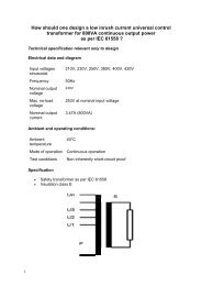
Insulation cl<strong>as</strong>s E is prescribed.<br />
Criterion for <strong>design</strong><br />
Normally, high-frequency <strong>transformer</strong>s have very low regulation and are<br />
<strong>design</strong>ed according to the prescribed tem<strong>per</strong>ature rise.<br />
Since these <strong>transformer</strong>s are manufactured almost exclusively using ferrite, the<br />
optimum o<strong>per</strong>ating tem<strong>per</strong>ature is around 100°C.<br />
Bobbin unit<br />
In order to protect the transistors, high-frequency <strong>transformer</strong>s <strong>should</strong> be<br />
manufactured for low scatter, with single-chamber bobbin units. For this re<strong>as</strong>on,<br />
we very often arrive at dual-wire or interleaved windings.<br />
Ferrite quality<br />
Since the optimum o<strong>per</strong>ating tem<strong>per</strong>ature of ferrite for high-frequency<br />
<strong>transformer</strong>s over 100VA is around 100°C and their ambient tem<strong>per</strong>ature is<br />
between 40°C and 70°C, our <strong>design</strong> <strong>as</strong>sumption must be for an tem<strong>per</strong>ature rise<br />
of between 30°K and 60°K. If the core losses in relation to tem<strong>per</strong>ature rise are<br />
not economically acceptable, then the computer program will optimise or reduce<br />
induction automatically. But this does indicate that the selected ferrite quality is<br />
not optimized.<br />
Induction and ferrite quality<br />
High-frequency <strong>transformer</strong>s are equipped almost exclusively with ferrite. The<br />
program calculates both the active and the reactive core losses by<br />
hypothesizing the ferrite type, the frequency, the form of input voltage, induction<br />
and core tem<strong>per</strong>ature. The induction <strong>should</strong> be selected such that the<br />
<strong>transformer</strong> does not saturate at maximum input voltage and maximum core<br />
tem<strong>per</strong>ature.<br />
Cop<strong>per</strong> additional losses<br />
With a high-frequency <strong>transformer</strong>, the distinctions are drawn between the<br />
following additional losses in a winding, over and above the dc-current losses:<br />
• Eddy current losses<br />
• Displacement losses<br />
• Proximity effect losses<br />
• Losses due to circulating currents through the parallel-connected wires.<br />
Additional losses are smaller in the c<strong>as</strong>e of a winding that takes up only 30-60%<br />
of the available winding space. For that re<strong>as</strong>on, <strong>one</strong> <strong>should</strong> always set the input<br />
for the filling factor between 0.3 and 0.6 for purposes of automatic core<br />
selection.<br />
The input for Rac/Rdc will limit the extent of additional losses (eddy current<br />
losses and displacement losses). The computer program selects a high enough<br />
number of parallel-connected wires for the eddy current losses and<br />
displacement losses to fall short of the prescribed value for Rac/Rdc. For that<br />
re<strong>as</strong>on, the input for Rac/Rdc is also used for monitoring of parallel-connected<br />
wires. The value is normally set between 1.5 and 5.<br />
Proximity effects can be reduced by means of the Spread input. Another option<br />
for reducing proximity effects is to select wires with thicker insulation.