EA 4035-SERIES 3½ DIGIT VOLTMETER MODULE LED- / LCD ...
EA 4035-SERIES 3½ DIGIT VOLTMETER MODULE LED- / LCD ...
EA 4035-SERIES 3½ DIGIT VOLTMETER MODULE LED- / LCD ...

You also want an ePaper? Increase the reach of your titles
YUMPU automatically turns print PDFs into web optimized ePapers that Google loves.
12.02<br />
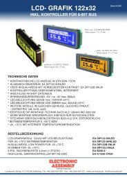
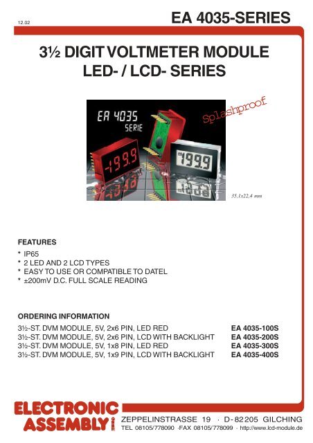
<strong>EA</strong> <strong>4035</strong>-<strong>SERIES</strong><br />
<strong>3½</strong> <strong>DIGIT</strong> <strong>VOLTMETER</strong> <strong>MODULE</strong><br />
<strong>LED</strong>- / <strong>LCD</strong>- <strong>SERIES</strong><br />
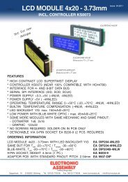
F<strong>EA</strong>TURES<br />
* IP65<br />
* 2 <strong>LED</strong> AND 2 <strong>LCD</strong> TYPES<br />
* <strong>EA</strong>SY TO USE OR COMPATIBLE TO DATEL<br />
* ±200mV D.C. FULL SCALE R<strong>EA</strong>DING<br />
Splashproof<br />
35,1x22,4 mm<br />
ORDERING INFORMATION<br />
<strong>3½</strong>-ST. DVM <strong>MODULE</strong>, 5V, 2x6 PIN, <strong>LED</strong> RED <strong>EA</strong> <strong>4035</strong>-100S<br />
<strong>3½</strong>-ST. DVM <strong>MODULE</strong>, 5V, 2x6 PIN, <strong>LCD</strong> WITH BACKLIGHT <strong>EA</strong> <strong>4035</strong>-200S<br />
<strong>3½</strong>-ST. DVM <strong>MODULE</strong>, 5V, 1x8 PIN, <strong>LED</strong> RED <strong>EA</strong> <strong>4035</strong>-300S<br />
<strong>3½</strong>-ST. DVM <strong>MODULE</strong>, 5V, 1x9 PIN, <strong>LCD</strong> WITH BACKLIGHT <strong>EA</strong> <strong>4035</strong>-400S<br />
ZEPPELINSTRASSE 19 · D- 82205 GILCHING<br />
TEL 08105/778090 ·FAX 08105/778099 · http://www.lcd-module.de
12.01<br />
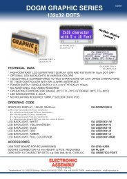
<strong>EA</strong> <strong>4035</strong>-100S<br />
<strong>3½</strong> <strong>DIGIT</strong> <strong>LED</strong> <strong>VOLTMETER</strong> <strong>MODULE</strong><br />
Splashproof<br />
F<strong>EA</strong>TURES<br />
* 200mV D.C. FULL SCALE R<strong>EA</strong>DING<br />
* typ. 50mA @ +5V±5% D.C. POWER SUPPLY<br />
* BRIGHT RED<br />
* 9.4mm (0.37") <strong>DIGIT</strong> HEIGHT<br />
* PROGRAMMABLE DECIMAL POINTS<br />
* <strong>LED</strong> DISPLAY<br />
* DISPLAY BLANKING FACILITY<br />
* SPLASH PROOF<br />
* AUTO-ZERO AND AUTO-POLARITY<br />
35,1x22,4 mm<br />
ORDERING INFORMATION<br />
<strong>3½</strong>-ST. DVM <strong>MODULE</strong>, 5V, 2x6 PIN, <strong>LED</strong> RED <strong>EA</strong> <strong>4035</strong>-100S<br />
ZEPPELINSTRASSE 19 · D- 82205 GILCHING<br />
TEL 08105/778090 ·FAX 08105/778099 · http://www.lcd-module.de
<strong>EA</strong> <strong>4035</strong>-100S<br />
PRODUCT DESCRIPTION<br />
The <strong>EA</strong> <strong>4035</strong>-100S features a 200mV d.c. measurement range with auto-zero and auto-polarity.<br />
Decimal points are user selectable. The <strong>EA</strong> <strong>4035</strong>-100S features a negative rail generator which<br />
enables the meter to measure a signal referenced to its own power supply 0V. The bright red <strong>LED</strong><br />
display ensures excellent readability under low light conditions. It can be blanked in applications<br />
requiring low power operation. The module is easily fitted into the panel, using the fixing clip provided.<br />
The module’s low cost means it will suit high and low volume applications. The design of the panel<br />
meter’s housing and seal ensures splash proofing in many applications.<br />
SAFETY<br />
To comply with the Low Voltage Directive (LVD93/68/EEC), input voltages to the module's pins must<br />
not exceed 60Vdc. The user must ensure that the incorporation of the panel meter into the user's<br />
equipment conformsto the relevant sections of BS EN 61010 (Safety Requirements for Electrical<br />
Equipment for Measuring, Control and Laboratory Use).<br />
PANEL FITTING<br />
CIRCUIT DIAGRAM<br />
2
SCALING<br />
Two resistors Ra and Rb may<br />
be used to alter the full scale<br />
reading (FSR) of the meter -<br />
see table. The meter will have<br />
to be recalibrated by adjusting<br />
the calibration potentiometer<br />
on the rear of the module.<br />
<strong>EA</strong> <strong>4035</strong>-100S<br />
APPLICATIONS<br />
Do not connect more than one meter to the same power supply if the meters cannot use the same<br />
signal ground. Taking any input beyond the power supply rails will damage the meter.<br />
Measuring an input voltage<br />
referenced to a floating supply,<br />
i.e. the input voltage and the<br />
meter’s power supply are<br />
isolated from each other.<br />
Measuring supply voltage and current to a load.<br />
S 1 selects between voltage and current measurement.<br />
Ra and Rb shown scaled for200V FSR<br />
Rs = 200mV (e.g. 0.1Ω/400mW for 2A full scale)<br />
I FSR<br />
Measuring a single ended input<br />
voltage referenced to supply, i.e.<br />
the input voltage and the meter’s<br />
power supply share the same 0V<br />
rail.<br />
Display DP1, DP2 or DP3, by connecting to 0V, as required.<br />
Voltage<br />
Vin<br />
Current<br />
Iin<br />
FSR Ra Rb<br />
2V 910k** 100k<br />
20V 1M** 10k<br />
200V 1M** 1k<br />
2000V* 1M** 100R<br />
200uA 0R 1k<br />
2mA 0R 100R<br />
20mA 0R 10R<br />
200mA 0R 1R<br />
* Ensure that Ra is rated for high voltage use.<br />
** Ensure solder link LA is cut.<br />
Measuring a 4-20mA loop current.<br />
The meter’s power supply must be<br />
isolated from the 4-20mA current<br />
loop.<br />
R= Reading at 20mA<br />
160<br />
Measuring current.<br />
The meter’s supply is isolated<br />
from the current being measured.<br />
3
<strong>EA</strong> <strong>4035</strong>-100S<br />
DIMENSION PINOUT<br />
all Dimensions are in mm (inch)<br />
Panel Cutout 34x21,3 mm<br />
PIN FUNCTION<br />
PIN FUNCTION<br />
Pin Symbol Function<br />
1 V+ Positive power supply to the meter.<br />
Display Enable. Connect to V+ for normal operation.<br />
2 DE Do not connect to enter low power mode.The display is then blanked, but the voltmeter section continues<br />
to operate. In low power mode, the current consumption is reduced to 400uA (typ).<br />
3 0V 0V power supply connection to the meter.<br />
4 DP1 Connect to 0V to display DP1 (199.9).<br />
5 DP2 Connect to 0V to display DP2 (19.99).<br />
6 DP3 Connect to 0V to display DP3 (1.999).<br />
7 RI Reference voltage input for the meter’s A/D converter.<br />
8 RO Precision reference voltage output. Connect to RI for normal operation.<br />
9 T Connect to V+ to test the display. All segments will be displayed, except for decimal points.<br />
Ground for analogue section of A/D converter.<br />
10 COM It is actively held at 3.05V (nom) below V+ and must not be allowed to sink excessive current (>100uA)<br />
by, for instance, connecting to a higher voltage.<br />
11 INH Positive measuring input.<br />
12 INL Negative measuring input.<br />
ELECTRICAL SPECIFICATIONS BLOCK DIAGRAM<br />
Specification Min. Typ. Max. Unit<br />
Accuracy (overall error) * 0.1 %(±1 count)<br />
Linearity ±1 count<br />
Sample rate 2.5 samples/sec<br />
Operating temperature range 0 50 °C<br />
Warm-up time 10 minute<br />
Temperature stability 150 ppm/°C<br />
Supply voltage 4.75 5 5.25 V<br />
Supply current (DE connected to V+) 50 90 mA<br />
Supply current (DE connected to 0V) 400 uA<br />
Input leakage current (Vin = 0V) 1 10 pA<br />
ZEPPELINSTRASSE 19 · D- 82205 GILCHING<br />
TEL 08105/778090 ·FAX 08105/778099 · http://www.lcd-module.de<br />
ATTENTION<br />
handling precautions!
12.01<br />
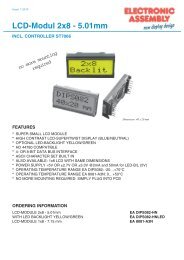
<strong>EA</strong> <strong>4035</strong>-200S<br />
<strong>3½</strong> <strong>DIGIT</strong> <strong>LCD</strong> <strong>VOLTMETER</strong> <strong>MODULE</strong><br />
Splashproof<br />
F<strong>EA</strong>TURES<br />
* 9.75mm (0.38") <strong>LCD</strong> <strong>DIGIT</strong> HEIGHT<br />
* ±200mV D.C. FULL SCALE R<strong>EA</strong>DING<br />
* 350µA @ +5V±5% D.C. POWER SUPPLY<br />
* PROGRAMMABLE DECIMAL POINTS<br />
* <strong>LED</strong> BACKLIGHTING<br />
* LOW BATTERY WARNING<br />
* DISPLAY BLANKING FACILITY<br />
* SPLASH PROOF<br />
* AUTO-ZERO AND AUTO-POLARITY<br />
35,1x22,4 mm<br />
ORDERING INFORMATION<br />
<strong>3½</strong>-ST. DVM <strong>MODULE</strong>, 5V, 2x6 PIN, <strong>LCD</strong> WITH BACKLIGHT <strong>EA</strong> <strong>4035</strong>-200S<br />
ZEPPELINSTRASSE 19 · D- 82205 GILCHING<br />
TEL 08105/778090 ·FAX 08105/778099 · http://www.lcd-module.de
<strong>EA</strong> <strong>4035</strong>-200S<br />
PRODUCT DESCRIPTION<br />
The <strong>EA</strong> <strong>4035</strong>-100S features a 200mV d.c. measurement range with auto-zero and auto-polarity.<br />
Decimal points are user selectable. The <strong>EA</strong> <strong>4035</strong>-200S features a negative rail generator which<br />
enables the meter to measure a signal referenced to its own power supply 0V. The bright red <strong>LED</strong><br />
display ensures excellent readability under low light conditions. It can be blanked in applications<br />
requiring low power operation. The module is easily fitted into the panel, using the fixing clip provided.<br />
The module’s low cost means it will suit high and low volume applications. The design of the panel<br />
meter’s housing and seal ensures splash proofing in many applications.<br />
SAFETY<br />
To comply with the Low Voltage Directive (LVD93/68/EEC), input voltages to the module's pins must<br />
not exceed 60Vdc. The user must ensure that the incorporation of the panel meter into the user's<br />
equipment conformsto the relevant sections of BS EN 61010 (Safety Requirements for Electrical<br />
Equipment for Measuring, Control and Laboratory Use).<br />
PANEL FITTING<br />
CIRCUIT DIAGRAM<br />
2
SCALING<br />
Two resistors Ra and Rb may<br />
be used to alter the full scale<br />
reading (FSR) of the meter -<br />
see table. The meter will have<br />
to be recalibrated by adjusting<br />
the calibration potentiometer<br />
on the rear of the module.<br />
<strong>EA</strong> <strong>4035</strong>-200S<br />
APPLICATIONS<br />
Do not connect more than one meter to the same power supply if the meters cannot use the same<br />
signal ground. Taking any input beyond the power supply rails will damage the meter.<br />
Measuring an input voltage<br />
referenced to a floating supply,<br />
i.e. the input voltage and the<br />
meter’s power supply are<br />
isolated from each other.<br />
Measuring supply voltage and current to a load.<br />
S 1 selects between voltage and current measurement.<br />
Ra and Rb shown scaled for200V FSR<br />
Measuring a single ended input<br />
voltage referenced to supply, i.e.<br />
the input voltage and the meter’s<br />
power supply share the same 0V<br />
rail.<br />
Rs = 200mV (e.g. 0.1Ω/400mW for 2A full scale)<br />
I FSR<br />
Display DP1, DP2 or DP3, by connecting to 0V, as required.<br />
Voltage<br />
Vin<br />
Current<br />
Iin<br />
FSR Ra Rb<br />
2V 910k** 100k<br />
20V 1M** 10k<br />
200V 1M** 1k<br />
2000V* 1M** 100R<br />
200uA 0R 1k<br />
2mA 0R 100R<br />
20mA 0R 10R<br />
200mA 0R 1R<br />
* Ensure that Ra is rated for high voltage use.<br />
** Ensure solder link LA is cut.<br />
Measuring a 4-20mA loop current.<br />
The meter’s power supply must be<br />
isolated from the 4-20mA current<br />
loop.<br />
R= Reading at 20mA<br />
160<br />
3
<strong>EA</strong> <strong>4035</strong>-200S<br />
DIMENSION PINOUT<br />
all Dimensions are in mm (inch)<br />
Panel Cutout 34x21,3 mm<br />
PIN FUNCTION<br />
Pin Symbol Function<br />
PIN FUNCTION<br />
1 V+ Positive power supply to the meter and <strong>LED</strong> backlighting.<br />
2 NC Not connected.<br />
3 0V 0V power supply connection to the meter.<br />
4 DP1 Connect to 0V to display DP1 (199.9).<br />
5 DP2 Connect to 0V to display DP2 (19.99).<br />
6 DP3 Connect to 0V to display DP3 (1.999).<br />
7 RI Reference voltage input for the meter’s A/D converter.<br />
8 RO Precision reference voltage output. Connect to RI for normal operation.<br />
9 BL Connect to GND to switch on the <strong>LED</strong> backlighting<br />
ELECTRICAL SPECIFICATIONS BLOCK DIAGRAM<br />
Specification Min. Typ. Max. Unit<br />
Accuracy (overall error) * 0.1 %(±1 count)<br />
Linearity ±1 count<br />
Sample rate 2.5 samples/sec<br />
Operating temperature range 0 50 °C<br />
Temperature stability 100 ppm/°C<br />
Supply voltage 3.5 5 5.25 V<br />
Supply current 350 µA<br />
Backlight Current @5V d.c. 40 80 mA<br />
Input leakage current (Vin = 0V) 1 10 pA<br />
ZEPPELINSTRASSE 19 · D- 82205 GILCHING<br />
TEL 08105/778090 ·FAX 08105/778099 · http://www.lcd-module.de<br />
ATTENTION<br />
handling precautions!<br />
10 COM<br />
Ground for analogue section of A/D converter.<br />
It is actively held at 3.05V (nom) below V+ and must not be allowed to sink excessive current (>100uA)<br />
by, for instance, connecting to a higher voltage.<br />
11 INH Positive measuring input.<br />
12 INL Negative measuring input.<br />
Note:<br />
A negative supply is generated internally and mirrors the positive supply. For example: if V+is +5V, then the internally<br />
generated V- is -5V. When measuring with the input referenced to the same supply rail as that of the panel meter, then the<br />
limitations on the input range are (V- +1.5V) to (V+- 1.5V).
12.01<br />
<strong>EA</strong> <strong>4035</strong>-300S<br />
<strong>3½</strong> <strong>DIGIT</strong> <strong>LED</strong> <strong>VOLTMETER</strong> <strong>MODULE</strong><br />
Splashproof<br />
F<strong>EA</strong>TURES<br />
* ±200mV D.C. FULL SCALE R<strong>EA</strong>DING<br />
* typ. 50mA @ +5V±5% D.C. POWER SUPPLY<br />
* BRIGHT RED<br />
* 9.4mm (0.37") <strong>DIGIT</strong> HEIGHT<br />
* PROGRAMMABLE DECIMAL POINTS<br />
* BRIGHT RED <strong>LED</strong> DISPLAY<br />
* SIMPLYFIED CONNECTION<br />
* SPLASH PROOF<br />
* AUTO-ZERO AND AUTO-POLARITY<br />
35,1x22,4 mm<br />
ORDERING INFORMATION<br />
<strong>3½</strong>-ST. DVM <strong>MODULE</strong>, 5V, 1x8 PIN, <strong>LED</strong> RED <strong>EA</strong> <strong>4035</strong>-300S<br />
ZEPPELINSTRASSE 19 · D- 82205 GILCHING<br />
TEL 08105/778090 ·FAX 08105/778099 · http://www.lcd-module.dede
<strong>EA</strong> <strong>4035</strong>-300S<br />
PRODUCT DESCRIPTION<br />
The <strong>EA</strong> <strong>4035</strong>-300S features a 200mV d.c. measurement range with auto-zero and auto-polarity.<br />
Decimal points are user selectable. The <strong>EA</strong> <strong>4035</strong>-300S features a negative rail generator which<br />
enables the meter to measure a signal referenced to its own power supply 0V. The bright red <strong>LED</strong><br />
display ensures excellent readability under low light conditions. It can be blanked in applications<br />
requiring low power operation. The module is easily fitted into the panel, using the fixing clip provided.<br />
The module’s low cost means it will suit high and low volume applications. The design of the panel<br />
meter’s housing and seal ensures splash proofing in many applications.<br />
SAFETY<br />
To comply with the Low Voltage Directive (LVD93/68/EEC), input voltages to the module's pins must<br />
not exceed 60Vdc. The user must ensure that the incorporation of the panel meter into the user's<br />
equipment conformsto the relevant sections of BS EN 61010 (Safety Requirements for Electrical<br />
Equipment for Measuring, Control and Laboratory Use).<br />
PANEL FITTING<br />
CIRCUIT DIAGRAM<br />
2
SCALING<br />
Two resistors Ra and Rb may<br />
be used to alter the full scale<br />
reading (FSR) of the meter -<br />
see table. The meter will have<br />
to be recalibrated by adjusting<br />
the calibration potentiometer<br />
on the rear of the module.<br />
<strong>EA</strong> <strong>4035</strong>-300S<br />
APPLICATIONS<br />
Do not connect more than one meter to the same power supply if the meters cannot use the same<br />
signal ground. Taking any input beyond the power supply rails will damage the meter.<br />
Measuring an input voltage<br />
referenced to a floating supply,<br />
i.e. the input voltage and the<br />
meter’s power supply are<br />
isolated from each other.<br />
Measuring supply voltage and current to a load.<br />
S 1 selects between voltage and current measurement.<br />
Ra and Rb shown scaled for200V FSR<br />
Rs = 200mV (e.g. 0.1Ω/400mW for 2A full scale)<br />
I FSR<br />
Measuring a single ended input<br />
voltage referenced to supply, i.e.<br />
the input voltage and the meter’s<br />
power supply share the same 0V<br />
rail.<br />
Display DP1, DP2 or DP3, by connecting to 0V, as required.<br />
Voltage<br />
Vin<br />
Current<br />
Iin<br />
FSR Ra Rb<br />
2V 910k** 100k<br />
20V 1M** 10k<br />
200V 1M** 1k<br />
2000V* 1M** 100R<br />
200uA 0R 1k<br />
2mA 0R 100R<br />
20mA 0R 10R<br />
200mA 0R 1R<br />
* Ensure that Ra is rated for high voltage use.<br />
** Ensure solder link LA is cut.<br />
Measuring a 4-20mA loop current.<br />
The meter’s power supply must be<br />
isolated from the 4-20mA current<br />
loop.<br />
R= Reading at 20mA<br />
160<br />
Measuring current.<br />
The meter’s supply is isolated<br />
from the current being measured.<br />
3
<strong>EA</strong> <strong>4035</strong>-300S<br />
DIMENSION PINOUT<br />
all Dimensions are in mm (inch)<br />
Panel Cutout 34x21,3 mm<br />
PIN FUNCTION<br />
PIN FUNCTION<br />
Pin Symbol Function<br />
1 V+ Positive power supply to the meter.<br />
2 0V 0V power supply connection to the meter.<br />
3 COM<br />
Ground for analogue section of A/D converter.<br />
It is actively held at 3.05V (nom) below V+ and must not be allowed to sink excessive current (>100uA)<br />
by, for instance, connecting to a higher voltage.<br />
4 INH Positive measuring input.<br />
5 INL Negative measuring input.<br />
6 DP1 Connect to 0V to display DP1 (199.9).<br />
7 DP2 Connect to 0V to display DP2 (19.99).<br />
8 DP3 Connect to 0V to display DP3 (1.999).<br />
ELECTRICAL SPECIFICATIONS BLOCK DIAGRAM<br />
Specification Min. Typ. Max. Unit<br />
Accuracy (overall error) * 0.1 %(±1 count)<br />
Linearity ±1 count<br />
Sample rate 2.5 samples/sec<br />
Operating temperature range 0 50 °C<br />
Warm-up time 10 minute<br />
Temperature stability 150 ppm/°C<br />
Supply voltage 4.75 5 5.25 V<br />
Supply current 50 90 mA<br />
Input leakage current (Vin = 0V) 1 10 pA<br />
ZEPPELINSTRASSE 19 · D- 82205 GILCHING<br />
TEL 08105/778090 ·FAX 08105/778099 · http://www.lcd-module.de<br />
Solder Link:<br />
LCOM Normally Open. Connects INL to COM.<br />
ATTENTION<br />
handling precautions!
12.02<br />
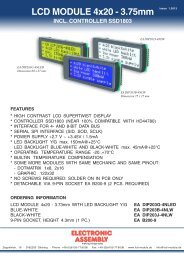
<strong>EA</strong> <strong>4035</strong>-400S<br />
<strong>3½</strong> <strong>DIGIT</strong> <strong>LCD</strong> <strong>VOLTMETER</strong> <strong>MODULE</strong><br />
Splashproof<br />
F<strong>EA</strong>TURES<br />
* 9.75mm (0.38") <strong>LCD</strong> <strong>DIGIT</strong> HEIGHT<br />
* ±200mV D.C. FULL SCALE R<strong>EA</strong>DING<br />
* 3.5 TO 7V OR 7.5 TO 14V OPERATION<br />
* typ. 40mA @ +5V±5% D.C. POWER SUPPLY<br />
* <strong>LED</strong> BACKLIGHTING<br />
* PROGRAMMABLE DECIMAL POINTS<br />
* LOW BATTERY WARNING<br />
* SIMPLYFIED CONNECTION<br />
* SPLASH PROOF<br />
* AUTO-ZERO AND AUTO-POLARITY<br />
35,1x22,4 mm<br />
ORDERING INFORMATION<br />
<strong>3½</strong>-ST. DVM <strong>MODULE</strong>, 5V, 1x9 PIN, <strong>LCD</strong> WITH BACKLIGHT <strong>EA</strong> <strong>4035</strong>-400S<br />
ZEPPELINSTRASSE 19 · D- 82205 GILCHING<br />
TEL 08105/778090 ·FAX 08105/778099 · http://www.lcd-module.de
<strong>EA</strong> <strong>4035</strong>-400S<br />
PRODUCT DESCRIPTION<br />
The <strong>EA</strong> <strong>4035</strong>-400S features a 200mV d.c. measurement range with auto-zero and auto-polarity.<br />
Decimal points are user selectable.<br />
<strong>LED</strong> backlighting ensures excellent readability under low light conditions. The module is easily fitted<br />
into the panel, using the fixing clip provided. The <strong>EA</strong> <strong>4035</strong>-400S features a negative rail generator<br />
which enables the meter to measure a signal referenced to its own power supply GND.<br />
low cost means it will suit high and low volume applications. The design of the panel meter’s housing<br />
ensures splash proofing using the supplied seal.<br />
SAFETY<br />
To comply with the Low Voltage Directive (LVD93/68/EEC), input voltages to the module's pins must<br />
not exceed 60Vdc. The user must ensure that the incorporation of the panel meter into the user's<br />
equipment conformsto the relevant sections of BS EN 61010 (Safety Requirements for Electrical<br />
Equipment for Measuring, Control and Laboratory Use).<br />
PANEL FITTING<br />
CIRCUIT DIAGRAM<br />
2
SCALING<br />
Two resistors Ra and Rb may<br />
be used to alter the full scale<br />
reading (FSR) of the meter -<br />
see table. The meter will have<br />
to be recalibrated by adjusting<br />
the calibration potentiometer<br />
on the rear of the module.<br />
APPLICATIONS<br />
<strong>EA</strong> <strong>4035</strong>-400S<br />
Voltage<br />
Vin<br />
Current<br />
Iin<br />
FSR Ra Rb<br />
2V 910k** 100k<br />
20V 1M** 10k<br />
200V 1M** 1k<br />
2000V* 1M** 100R<br />
200uA 0R 1k<br />
2mA 0R 100R<br />
20mA 0R 10R<br />
200mA 0R 1R<br />
Do not connect more than one meter to the same power supply if the meters cannot use the same<br />
signal ground. Taking any input beyond the power supply rails will damage the meter.<br />
3.5 to 7V Meter Power Supply<br />
Measuring a single ended input voltage<br />
referenced to supply, i.e. the input<br />
voltage and the meter’s power supply<br />
share the same 0V rail.<br />
Ensure solder link LCOM is open.<br />
7.5 to 14V Meter Power Supply<br />
Measuring a single ended input voltage<br />
referenced to supply, i.e. the input<br />
voltage and the meter’s power supply<br />
share the same 0V rail.<br />
Ensure solder link LCOM is open.<br />
Measuring an input voltage<br />
referenced to a floating supply, i.e.<br />
the input voltage and the meter’s<br />
power supply are isolated<br />
from each other.<br />
Ensure solder link LCOM is closed.<br />
Measuring an input voltage referenced<br />
to a floating supply, i.e. the input<br />
voltage and the meter’s power supply<br />
are isolated from each other.<br />
Ensure solder link LCOM is closed.<br />
* Ensure that Ra is rated for high voltage use.<br />
** Ensure solder link LA is cut.<br />
Measuring a current from a circuit which is<br />
floating with respect to the DPM’s supply,<br />
i.e. the current and the meter’s power<br />
supply are isolated from each other.<br />
Ensure solder link LCOM is closed.<br />
Measuring a current from a circuit<br />
which is floating with respect to the<br />
DPM’s supply, i.e. the current and the<br />
meter’s power supply are isolated from<br />
each other.<br />
Ensure solder link LCOM is closed.<br />
3
<strong>EA</strong> <strong>4035</strong>-400S<br />
DIMENSION PINOUT<br />
all Dimensions are in mm (inch)<br />
Panel Cutout 34x21,3 mm<br />
PIN FUNCTION<br />
Pin Symbol Function<br />
1 V+ Positive power supply to the meter<br />
PIN FUNCTION<br />
2 GND 0V power supply connection to the meter (3.0 to 7.5V meter power supply appl. only)<br />
3 BL-<br />
Connect to meter's negative supply GND or V- to switch on the <strong>LED</strong> backlighting<br />
For meter supply above 5V, add a series resistor Rs<br />
4 INH Positive measuring input<br />
5 INL Negative measuring input<br />
6 DP1 Connect to 0V to display DP1 (199.9)<br />
7 DP2 Connect to 0V to display DP2 (19.99)<br />
8 DP3 Connect to 0V to display DP3 (1.999)<br />
9 V- Negative power supply to the meter (6.0 to 15.0V meter power supply appl. only)<br />
ELECTRICAL SPECIFICATIONS BLOCK DIAGRAM<br />
Specification Min. Typ. Max. Unit<br />
Accuracy (overall error) * 0.1 %(±1 count)<br />
Linearity ±1 count<br />
Sample rate 2.5 samples/sec<br />
Operating temperature range 0 50 °C<br />
Temperature stability 100 ppm/°C<br />
Supply voltage<br />
Supply current<br />
V+ to GND configuration 3.5 5 7 V<br />
V+ to V- configuration 7.5 9 14 V<br />
V+ to GND configuration 350 µA<br />
V+ to V- configuration 350 µA<br />
Backlight current @5V d.c. 20 40 mA<br />
Input leakage current (Vin = 0V) 1 10 pA<br />
ZEPPELINSTRASSE 19 · D- 82205 GILCHING<br />
TEL 08105/778090 ·FAX 08105/778099 · http://www.lcd-module.de<br />
Solder Links:<br />
LCOM Normally Open. Connects INL to COM.<br />
LBAT Normally Closed. Cut this link to disable<br />
the lowbattery warning sign.<br />
ATTENTION<br />
handling precautions!<br />
Note:<br />
A negative supply is generated internally and mirrors the positive supply. For example: if V+is +5V, then the internally<br />
generated V- is -5V. When measuring with the input referenced to the same supply rail as that of the panel meter, then the<br />
limitations on the input range are (V- +1.5V) to (V+- 1.5V).