EA DIP204-4 LCD MODULE 4x20 - 3.73mm - Electronic Assembly
EA DIP204-4 LCD MODULE 4x20 - 3.73mm - Electronic Assembly
EA DIP204-4 LCD MODULE 4x20 - 3.73mm - Electronic Assembly

You also want an ePaper? Increase the reach of your titles
YUMPU automatically turns print PDFs into web optimized ePapers that Google loves.
2.2010<br />
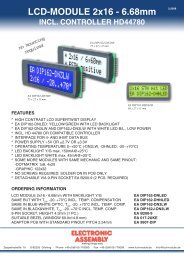
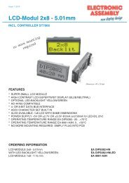
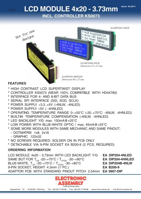
<strong>LCD</strong> <strong>MODULE</strong> <strong>4x20</strong> - <strong>3.73mm</strong><br />
INCL. CONTROLLER KS0073<br />
Not for new<br />
designs<br />
<strong>EA</strong> <strong>DIP204</strong>-4HNLED<br />
Dimension 68 x 27 mm<br />
<strong>EA</strong> <strong>DIP204</strong>B-4NLW<br />
Dimension 75 x 27 mm<br />
Issue 04.2011<br />
<strong>EA</strong> <strong>DIP204</strong>J-4NLW<br />
F<strong>EA</strong>TURES<br />
* HIGH CONTRAST <strong>LCD</strong> SUPERTWIST DISPLAY<br />
* CONTROLLER KS0073 (N<strong>EA</strong>R 100% COMPATIBLE WITH HD44780)<br />
* INTERFACE FOR 4- AND 8-BIT DATA BUS<br />
* SERIAL SPI INTERFACE (SID, SOD, SCLK)<br />
* POWER SUPPLY +3.3..+5V (-4NLW, -4NLED)<br />
* POWER SUPPLY +5V ( -4HNLED)<br />
* OPERATING TEMPERATURE RANGE 0~+50°C (-20..+70°C: -4NLW, -4HNLED)<br />
* BUILT-IN TEMPERATURE COMPENSATION (-4NLW, -4HNLED)<br />
* LED BACKLIGHT Y/G max. 150mA@+25°C<br />
* LOW POWER WITH BLUE-WHITE OPTIC / max. 45mA@+25°C<br />
* SOME MORE <strong>MODULE</strong>S WITH SAME MECHANIC AND SAME PINOUT:<br />
- DOTMATRIX 1x8, 2x16<br />
- GRAPHIC 122x32<br />
* NO SCREWS REQUIRED: SOLDER ON IN PCB ONLY<br />
* DETACHABLE VIA 9-PIN SOCKET <strong>EA</strong> B200-9 (2 PCS. REQUIRED)<br />
ORDERING INFORMATION<br />
<strong>LCD</strong> <strong>MODULE</strong> <strong>4x20</strong> - <strong>3.73mm</strong> WITH LED BACKLIGHT Y/G <strong>EA</strong> <strong>DIP204</strong>-4NLED<br />
SAME BUT FOR T -20~+70°C / T -30~+80°C <strong>EA</strong> <strong>DIP204</strong>-4HNLED<br />
OP. STOR.<br />
BLUE-WHITE, T -20~+70°C / T -30~+80°C <strong>EA</strong> <strong>DIP204</strong>B-4NLW<br />
OP. STOR.<br />
9-PIN SOCKET, HEIGHT 4.3mm (1 PC.) <strong>EA</strong> B200-9<br />
ADAPTOR PCB WITH STANDARD PINOUT PITCH 2.54mm <strong>EA</strong> 9907-DIP<br />
Zeppelinstr. 19 · D-82205 Gilching · Tel. 08105-778090 · Fax 08105-778099 · www.lcd-module.de · info@lcd-module.de
<strong>EA</strong> <strong>DIP204</strong>-4<br />
Page 2<br />
PINOUT<br />
Pin Symbol Level Function Pin Symbol Level Function<br />
1 VSS L Power Supply 0V (GND) 10 D3 H / L Display Data<br />
2 VDD H Power Supply +5V 11 D4 (D0) H / L Display Data<br />
3 VEE - Contrast adjustment, input 12 D5 (D1) H / L Display Data<br />
4 RS (CS) H / L H=Data, L=Command 13 D6 (D2) H / L Display Data<br />
5<br />
R/W<br />
(SID)<br />
H / L H=Read, L=Write 14 D7 (D3) H / L Display Data, MSB<br />
6 E (SCLK) H Enable (falling edge) 15 - - NC (see <strong>EA</strong> DIP122-5N)<br />
7 D0 (SOD) H / L Display Data, LSB 16 RES L Reset (internal Pullup 10k)<br />
8 D1 H / L Display Data 17 A - LED B/L+ Resistor required<br />
9 D2 H / L Display Data 18 C - LED B/L-<br />
TABEL OF COMMAND (KS0073, IE=HIGH)<br />
Instruction<br />
RE<br />
Bit<br />
RS R/W DB<br />
7<br />
DB<br />
6<br />
C ode<br />
Clear Display * 0 0 0 0 0 0 0 0 0 1<br />
Cursor At Home 0 0 0 0 0 0 0 0 0 1 *<br />
Power Down<br />
Mode<br />
Entry Mode Set<br />
Display On/Off<br />
Control<br />
extended<br />
Function Set<br />
Cursor / Display<br />
Shift<br />
DB<br />
5<br />
DB<br />
4<br />
DB<br />
3<br />
DB<br />
2<br />
DB<br />
1<br />
DB<br />
0<br />
Description<br />
Clears all display and returns the cursor to the<br />
home position (Address 0).<br />
Returns the Cursor to the home position (Address<br />
0). Also returns the display being shifted to the<br />
original position. DD RAM contents remain<br />
unchanged.<br />
1 0 0 0 0 0 0 0 0 1<br />
Set Power down mode bit.<br />
PD PD=0: powerdown mode disable<br />
PD=1: powerdown mode enable<br />
0 0 0 0 0 0 0 0 1 I/D S<br />
Cursor moving direction (I/D=0: dec; I/D=1: inc)<br />
shift enable bit (S=0: disable; S=1: enable shift)<br />
1 0 0 0 0 0 0 0 1 1<br />
Segment bidirectional function<br />
BID<br />
(BID=0: Seg1->Seg60; BID=1: Seg60->Seg1)<br />
D=0: display off; D=1: display on<br />
0 0 0 0 0 0 0 1 D C B C=0: cursor off; C=1: cursor on<br />
B=0: blink off; B=1: blink on<br />
FW=0: 5-dot font width; FW=1: 6-dot font width<br />
1 0 0 0 0 0 0 1 FW BW NW BW=0: normal cursor; BW=1: inverting cursor<br />
NW=0: 1- or 2-line (see N); NW=1: 4-line display<br />
Moves the Cursor or shifts the display<br />
0 0 0 0 0 0 1 S/C R/L * * S/C=0: cursor Shift; S/C=1: display shift<br />
R/L=0: shift to left; R/L=1: shift to right<br />
Execute<br />
Time<br />
(270kHz)<br />
1.53ms<br />
1.53ms<br />
Scroll Enable 1 0 0 0 0 0 1 H4 H3 H2 H1 Determine the line for horizontal scroll 39µs<br />
Function Set<br />
CG RAM<br />
Address Set<br />
SEG RAM<br />
Address Set<br />
DD RAM<br />
Address Set<br />
Set Scroll<br />
Quantity<br />
Busy Flag /<br />
Address Read<br />
0 0 0 0 0 1 DL N<br />
sets interface data length (DL=0:4-bit; DL=1:8-bit)<br />
number of display lines (N=0: 1-line; N=1: 2-line)<br />
RE DH RE extension register (RE= 0/1)<br />
scroll/shift (DH=0: dot scroll; DH=1: display shift)<br />
reverse bit (REV=0:normal; REV=1:inverse display)<br />
1 0 0 0 0 1 DL N<br />
CG-/SEG-RAM blink (BE=0: disable; BE=1: enable)<br />
RE BE LP<br />
LP=0: normal mode; LP=1: low power mode<br />
0 0 0 0 1 AC<br />
Sets the CG RAM address. CG RAM data is sent<br />
and received after this setting.<br />
1 0 0 0 1 * * AC<br />
Sets the SEG RAM address. SEG RAM data is sent<br />
and received after this setting.<br />
0 0 0 1 AC<br />
Sets the DD RAM address. DD RAM data is sent<br />
and received after this setting.<br />
1 0 0 1 * SQ Sets the quantity of horizontal dot scroll (DH=0) 39µs<br />
* 0 1 BF AC<br />
Write Data * 1 0 Write Data<br />
Read Data * 1 1 Read Data<br />
Reads Busy flag (BF) indicating internal operation is<br />
being performed and reads address counter<br />
contents.<br />
Writes data into internal RAM<br />
(DD RAM / CG RAM / SEGRAM)<br />
Reads data from internal RAM<br />
(DD RAM / CG RAM / SEGRAM)<br />
39µs<br />
39µs<br />
39µs<br />
39µs<br />
39µs<br />
39µs<br />
39µs<br />
39µs<br />
39µs<br />
39µs<br />
39µs<br />
-<br />
43µs<br />
43µs<br />
ELECTRONIC ASSEMBLY reserves<br />
the right to change specifications<br />
without prior notice. Printing and<br />
typographical errors reserved.<br />
BACKLIGHT<br />
Using the LED backlight requires an current source or external current-limiting resistor. Forward<br />
voltage for yellow/green backlight is 3.9~4.2V and for white LED backlight is 3.0~3.6V. Please take<br />
care of derating for T >+25°C.<br />
a<br />
Note: - Do never connect backlight direct to 5V; this may destroy backlight immediately !<br />
- Blue-white displays do always need a backlight for contrast (min. 5mA).
ELECTRONIC ASSEMBLY reserves<br />
the right to change specifications<br />
without prior notice. Printing and<br />
typographical errors reserved.<br />
INITIALISATION EXAMPLE FOR 8 BIT MODE<br />
Command RS R/W DB7 DB6 DB5 DB4 DB3 DB2 DB1 DB0 Hex Description<br />
Function Set 0 0 0 0 1 1 0 1 0 0 $34 8 bit data length, extension bit RE=1<br />
ext. Function Set 0 0 0 0 0 0 1 0 0 1 $09 4 line mode<br />
Function Set 0 0 0 0 1 1 0 0 0 0 $30 8 bit data length, extension bit RE=0<br />
Display ON/OFF 0 0 0 0 0 0 1 1 1 1 $0F display on, cursor on, cursor blink<br />
Clear Display 0 0 0 0 0 0 0 0 0 1 $01 clear display, cursor 1st. row, 1st. line<br />
Entry Mode Set 0 0 0 0 0 0 0 1 1 0 $06 cursor will be automatically incremented<br />
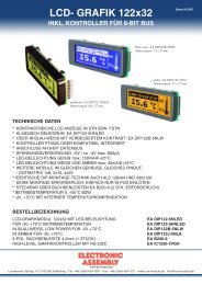
CHARACTER SET<br />
A full character set is built in already.<br />
Additionally to that 8 more characters can<br />
be defined individually.<br />
CONTRAST ADJUSTMENT<br />
Pin 3 requires driving voltage for contrast<br />
VEE. Adjustment can be done by external<br />
potentiometer for example.<br />
Note: In contrast to many other<br />
dotmatrix lcd modules input is<br />
supplied with VDD level here !<br />
<strong>EA</strong> <strong>DIP204</strong>-4NLED<br />
VEE<br />
VDD<br />
2,5k<br />
<strong>EA</strong> <strong>DIP204</strong>B-4NLW<br />
<strong>EA</strong> <strong>DIP204</strong>-4HNLED<br />
Both versions -4NLW and -4HNLEDdo<br />
have a built-in temperature<br />
compensatione; so there's no more need<br />
for contrats adjustment while operation<br />
anymore.<br />
<strong>EA</strong> <strong>DIP204</strong>-4<br />
Page 3<br />
Addressing:<br />
1st. line $00..$13<br />
2nd. line $20..$33<br />
3rd. line $40..$53<br />
4th. line $60..$73<br />
CR<strong>EA</strong>TING YOUR OWN CHARACTERS<br />
All these character display modules got the feature to create 8 own characters (ASCII Codes 0..7) in<br />
addition to the 240 ROM fixed codes.<br />
Set CG RAM Address Data<br />
1.) The command "CG RAM Address Set"<br />
defines the ASCII code (Bit 3,4,5) and the<br />
Adresse Hex<br />
7 6 5<br />
Bit<br />
4 3 2 1 0<br />
Hex<br />
dot line (Bit 0,1,2) of the new character.<br />
Example demonstrates creating ASCII<br />
code $00.<br />
2.) Doing 8 times the write command "Data<br />
0 1 0 0 0<br />
0<br />
0<br />
0<br />
0<br />
1<br />
0<br />
0<br />
1<br />
1<br />
0<br />
0<br />
1<br />
0<br />
1<br />
0<br />
$40<br />
$41<br />
$42<br />
$43<br />
$44<br />
X X X<br />
0<br />
0<br />
0<br />
0<br />
1<br />
0<br />
0<br />
0<br />
0<br />
0<br />
1<br />
1<br />
1<br />
1<br />
1<br />
0<br />
0<br />
0<br />
0<br />
0<br />
0<br />
0<br />
0<br />
0<br />
1<br />
$04<br />
$04<br />
$04<br />
$04<br />
$15<br />
Write" defines line by line the new<br />
1 0 1 $45 0 1 1 1 0 $0E<br />
character. 8th. byte stands for the cursor<br />
line.<br />
1<br />
1<br />
1<br />
1<br />
0<br />
1<br />
$46<br />
$47<br />
0<br />
0<br />
0<br />
0<br />
1<br />
0<br />
0<br />
0<br />
0<br />
0<br />
$04<br />
$00<br />
3.) The new defined character can be used as a "normal" ASCII code (0..7); use with "DD RAM<br />
Address Set" and "Data Write".
<strong>EA</strong> <strong>DIP204</strong>-4<br />
Page 4<br />
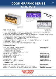
DIMENSIONS<br />
SERIAL MODE<br />
Factory set for interface is parallel with 4 bit or 8 bit data<br />
bus. Alternative module can be programmes with serial<br />
data stream. For that solder link 4/8 has to be opened<br />
and closed to SPI side. Specification for serial operation<br />
mode is written down in user manual for KS0073: http:/<br />
/www.lcd-module.de/eng/pdf/zubehoer/ks0073.pdf<br />
ADAPTOR PCB<br />
The adaptor pcb <strong>EA</strong> 9907-DIP is made for a quick<br />
function test for all DIP modules. This interface board<br />
provides the standard dotmatrix pinout with 1x14, 1x16,<br />
2x7 and 2x8 pins (0.1" pitch).<br />
ELECTRONIC ASSEMBLY reserves<br />
the right to change specifications<br />
without prior notice. Printing and<br />
typographical errors reserved.<br />
all dimensions are in mm<br />
ATTENTION<br />
handling precautions!<br />
Zeppelinstr. 19 · D-82205 Gilching · Tel. 08105-778090 · Fax 08105-778099 · www.lcd-module.de · info@lcd-module.de