EA DIP240-7 - Electronic Assembly
EA DIP240-7 - Electronic Assembly
EA DIP240-7 - Electronic Assembly

Create successful ePaper yourself
Turn your PDF publications into a flip-book with our unique Google optimized e-Paper software.
Issue 04.2011<br />
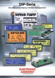
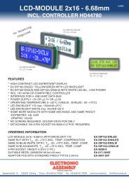
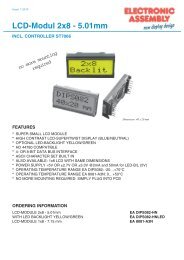
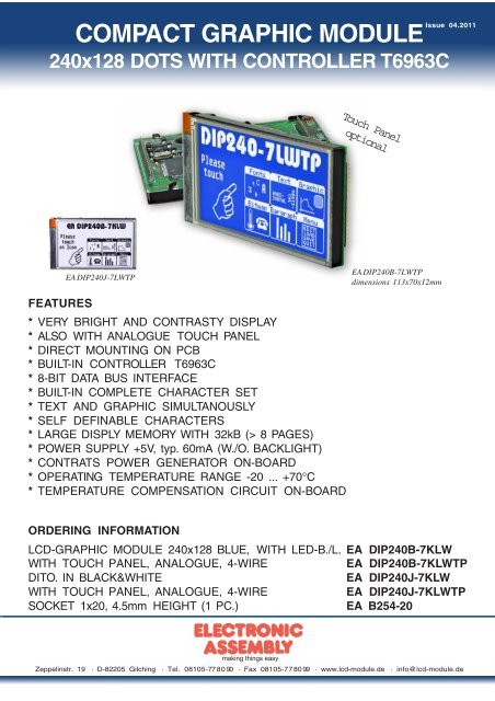
COMPACT GRAPHIC MODULE<br />
240x128 DOTS WITH CONTROLLER T6963C<br />
<strong>EA</strong> <strong>DIP240</strong>J-7LWTP<br />
F<strong>EA</strong>TURES<br />
* VERY BRIGHT AND CONTRASTY DISPLAY<br />
* ALSO WITH ANALOGUE TOUCH PANEL<br />
* DIRECT MOUNTING ON PCB<br />
* BUILT-IN CONTROLLER T6963C<br />
* 8-BIT DATA BUS INTERFACE<br />
* BUILT-IN COMPLETE CHARACTER SET<br />
* TEXT AND GRAPHIC SIMULTANOUSLY<br />
* SELF DEFINABLE CHARACTERS<br />
* LARGE DISPLY MEMORY WITH 32kB (> 8 PAGES)<br />
* POWER SUPPLY +5V, typ. 60mA (W./O. BACKLIGHT)<br />
* CONTRATS POWER GENERATOR ON-BOARD<br />
* OPERATING TEMPERATURE RANGE -20 ... +70°C<br />
* TEMPERATURE COMPENSATION CIRCUIT ON-BOARD<br />
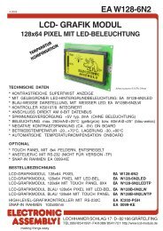
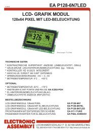
Touch Panel<br />
optional<br />
<strong>EA</strong> <strong>DIP240</strong>B-7LWTP<br />
dimensions 113x70x12mm<br />
ORDERING INFORMATION<br />
LCD-GRAPHIC MODULE 240x128 BLUE, WITH LED-B./L. <strong>EA</strong> <strong>DIP240</strong>B-7KLW<br />
WITH TOUCH PANEL, ANALOGUE, 4-WIRE <strong>EA</strong> <strong>DIP240</strong>B-7KLWTP<br />
DITO. IN BLACK&WHITE <strong>EA</strong> <strong>DIP240</strong>J-7KLW<br />
WITH TOUCH PANEL, ANALOGUE, 4-WIRE <strong>EA</strong> <strong>DIP240</strong>J-7KLWTP<br />
SOCKET 1x20, 4.5mm HEIGHT (1 PC.) <strong>EA</strong> B254-20<br />
Zeppelinstr. 19 · D-82205 Gilching · Tel. 08105-778090 · Fax 08105-778099 · www.lcd-module.de · info@lcd-module.de
<strong>EA</strong> <strong>DIP240</strong>-7<br />
Page 2<br />
ELECTRONIC ASSEMBLY reserves<br />
the right to change specifications<br />
without prior notice. Printing and<br />
typographical errors reserved.<br />
LC-GRAPHIC DISPLAY <strong>EA</strong> <strong>DIP240</strong>-7<br />
The very successful display line from ELECTRONIC ASSEMBLY, called DIP-series get's with it's<br />
<strong>EA</strong> P240-7 a new memer now. Simple placing and soldering into pcb will manage not even electrical<br />
contact but also mechanical mounting.<br />
The displays <strong>EA</strong> <strong>DIP240</strong>-7 provide a full graphic resolution of 240x128 dots and are at once all<br />
advantages of modern displays: standard controller T6963 on-board, fashionable LED- backlight with<br />
blue optic, single supply +5V, no additional power supply is required, wide operating temperature<br />
range incl. built-in temperature compensation.<br />
LED BACKLIGHT<br />
Both types are equipped wit a white LED-backlight. Please note that LEDs are wearable parts. Life<br />
time is between 1,000 and 20,000 hours *) , depending from ambient conditions. A current limiting<br />
resistor for max. 120mA is built-in already. Please take into account a derating for temeratures higher<br />
than >+25°C. To extend life time backlight can be switched on and off directly via processor port (pin<br />
LEDoff). Life time can be increase by reduction of driving current, too.<br />
CONTROLLER T6963C BUILT-IN<br />
All modules provide a built-in T6963C. Therefore a direct interface to 8-Bit processor system is<br />
available together with a comfortable command set. With that there's a complete caracter set built-in<br />
for example. This can be extended or completely exchanged by some self-definable characters, too.<br />
Every single character may be advised by a, attribute like "invers", "blink" or "invisible".<br />
More than 8 pages are available even in graphic mode (32kB). Text can be joined via "and-", "or-",<br />
"exor-" function with graphics layer.<br />
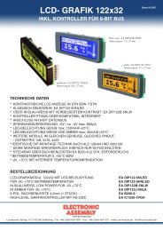
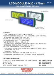
CONTRAST ADJUSTMENT<br />
Contrast pre-adjusted ex works. Thanks to the integrated temperature compensation there's no need<br />
to adjust while operation anymore.<br />
Is contrast adjustment requested nevertheless, an external potentiometer need to be<br />
connected and SMD potentiometer RV1 has to be desoldered. For external circuit please<br />
follow the schematic at the right.<br />
PINOUT<br />
Pin Symbol Function Pin Symbol Function<br />
1 N.C.<br />
21 GND Ground Potential for logic (0V)<br />
2 N.C. 22 VDD Power supply for logic (+5V)<br />
3 N.C. 23 RV Operating voltage for LC driving (input)<br />
4 N.C. 24 VEE Output voltage for LC driving<br />
5 N.C. 25 C/D L: Data input H: Command input<br />
6 N.C. 26 WR L: Data Write<br />
7 N.C. 27 RD L: Data Read<br />
8<br />
9<br />
N.C.<br />
N.C.<br />
Do not connect<br />
28<br />
29<br />
CE<br />
RST<br />
L: Chip Enable<br />
L: Reset<br />
10 N.C. 30 DB0 Data Bus Line, LSB<br />
11 N.C. 31 DB1 Data Bus Line<br />
12 N.C. 32 DB2 Data Bus Line<br />
13 N.C. 33 DB3 Data Bus Line<br />
14 N.C. 34 DB4 Data Bus Line<br />
15 N.C. 35 DB5 Data Bus Line<br />
16 N.C. 36 DB6 Data Bus Line<br />
17 BOTTOM Touch Panel 37 DB7 Data Bus Line, MSB<br />
18 LEFT Touch Panel 38 LEDoff L: LED off; Pull-up 100k built-in<br />
19 TOP Touch Panel 39 A LED backlight Anode +5V<br />
20 RIGHT Touch Panel 40 C LED backlight Cathode 0V *) Prior art
ELECTRONIC ASSEMBLY reserves<br />
the right to change specifications<br />
without prior notice. Printing and<br />
typographical errors reserved.<br />
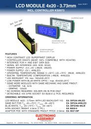
TOUCH PANEL<br />
Ordering code <strong>EA</strong> <strong>DIP240</strong>B-7KLWTP (and<br />
<strong>EA</strong> <strong>DIP240</strong>J-7LWTP of course) do include a built-in<br />
touch panel.<br />
Touch panel is an analogue one with 4-wire. Connection<br />
can be done via touch panel controller like MK712 from<br />
MICROCLOCK or ADS7846 from Burr-Brown. If there's a<br />
microcontroller with 4 switchable analogue inputs /digital<br />
outputs then touch panel can be conncted directly to the<br />
uC.<br />
CONTROLLER T6963C<br />
<strong>EA</strong> DIP 240-7<br />
Table below shows all commands of T6963C. A detailed description with timing informations you'll<br />
find in user manual "T 6963" (at http://www.lcd-module.de/eng/dbl/dbl.htm - controller).<br />
Command set T6963C<br />
Internal connection:<br />
MD0, MD1, MD2, FS0: GND<br />
MDS, MD3: VDD<br />
FS1: GND (LB3 open, 8x8)<br />
FS1:VDD (LB3 short, 6x8)<br />
Command<br />
Command Code<br />
D7 D6 D5 D4 D3 D2 D1 D0<br />
Pointer Set 0 0 1 0 0 N2 N1 N0<br />
Control Word Set 0 1 0 0 0 0 N1 N0<br />
Mode Set 1 0 0 0 CG N2 N1 N0<br />
Display Mode 1 0 0 1 N3 N2 N1 N0<br />
Cursor Pattern<br />
Select<br />
Data Auto<br />
Read/Write<br />
ATTENTION<br />
handling precautions!<br />
1 0 1 0 0 N2 N1 N0<br />
1 0 1 1 0 0 N1 N0<br />
Data Read/Write 1 1 0 0 0 N2 N1 N0<br />
Screen Peeking 1 1 1 0 0 0 0 0<br />
Screen Copy 1 1 1 0 1 0 0 0<br />
Bit Set/Reset 1 1 1 1 N3 N2 N1 N0<br />
N2<br />
0<br />
0<br />
1<br />
N2<br />
0<br />
0<br />
0<br />
1<br />
N2<br />
0<br />
1<br />
N1<br />
0<br />
1<br />
0<br />
N1<br />
0<br />
0<br />
1<br />
1<br />
N1<br />
0<br />
0<br />
1<br />
0<br />
N1<br />
0<br />
1<br />
N1<br />
0<br />
0<br />
1<br />
N0<br />
1<br />
0<br />
0<br />
N0<br />
0<br />
1<br />
0<br />
1<br />
N0<br />
0<br />
1<br />
1<br />
0<br />
N0<br />
0<br />
1<br />
N0<br />
0<br />
1<br />
*<br />
Technische Daten<br />
Spezifikation min typ max Einheit<br />
Cursor pointer set<br />
Offset register set<br />
Adress pointer set<br />
Page 3<br />
Widerstand<br />
x<br />
y<br />
650<br />
125<br />
700<br />
175<br />
750<br />
225<br />
Ω<br />
Ω<br />
Spannung 3 5 V<br />
Schaltstrom 5 25 mA<br />
Eigenkapazität 1.500 pF<br />
Betätigungskraft 45 65 g<br />
Kontaktprellen 5 10 ms<br />
Betriebstemperatur -20 +60 °C<br />
Lagertemperatur -20 +70 °C<br />
Transmission 75 85 %<br />
Lebensdauer 1.000.000 Schaltspiele<br />
Description Remark<br />
Text home address set<br />
Text area set<br />
Graphic home adress set<br />
Graphic area set<br />
Graphic and Text; CG=0: ROM, CG=1: RAM<br />
OR<br />
EXOR<br />
AND<br />
Text only (attribuite capability)<br />
N3=0: Graphic display off<br />
N3=1: Graphic display on<br />
N2=0: Text display off<br />
N2=1: Text display on<br />
N1=0: Cursor display off<br />
N1=1: Cursor display on<br />
N0=0: Cursor blink off<br />
N0=1: Cursor blink on<br />
specifies the number of cursor lines<br />
1 line cursor (bottom line)<br />
8 line cursor (8x8 dot cursor)<br />
Continous data can be written or read<br />
Data auto write set<br />
Data auto read set<br />
Auto reset<br />
Data read/write command for 1 byte<br />
N2=0: Address pointer up/down<br />
N2=1: Address pointer unchanged<br />
N1=0: Address pointer up<br />
N1=1: Address pointer down<br />
N0=0: Data write<br />
N0=1: Data read<br />
Transfer display data to data stack for read<br />
from CPU<br />
1 line display data which address is indicated<br />
by address pointer is copied to graphic RAM<br />
area<br />
N3=0: Bit reset<br />
N3=1: Bit set<br />
N2, N1, N0 indicates the bit in the pointed<br />
address (000 is LSB)<br />
Status<br />
Check<br />
Status<br />
Check<br />
Status<br />
Check<br />
Status<br />
Check<br />
Status<br />
Check
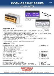
<strong>EA</strong> <strong>DIP240</strong>-7<br />
Page 4<br />
DIMENSIONS<br />
ELECTRONIC ASSEMBLY reserves<br />
the right to change specifications<br />
without prior notice. Printing and<br />
typographical errors reserved.<br />
Note:<br />
LC displays are generally not recommanded for wave<br />
soldering and reflow soldering. Temperatures above<br />
90°C may lead to permanent damage.<br />
Zeppelinstr. 19 · D-82205 Gilching · Tel. 08105-778090 · Fax 08105-778099 · www.lcd-module.de · info@lcd-module.de<br />
all dimensions are in mm