DOGM GRAPHIC SERIES - Electronic Assembly
DOGM GRAPHIC SERIES - Electronic Assembly
DOGM GRAPHIC SERIES - Electronic Assembly

You also want an ePaper? Increase the reach of your titles
YUMPU automatically turns print PDFs into web optimized ePapers that Google loves.
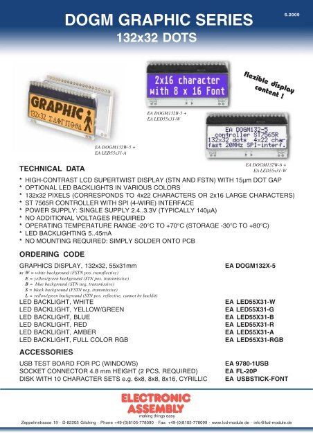
TECHNICAL DATA<br />
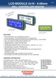
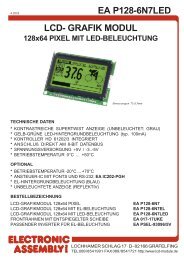
<strong>DOGM</strong> <strong>GRAPHIC</strong> <strong>SERIES</strong><br />
132x32 DOTS<br />
* HIGH-CONTRAST LCD SUPERTWIST DISPLAY (STN AND FSTN) WITH 15µm DOT GAP<br />
* OPTIONAL LED BACKLIGHTS IN VARIOUS COLORS<br />
* 132x32 PIXELS (CORRESPONDS TO 4x22 CHARACTERS OR 2x16 LARGE CHARACTERS)<br />
* ST 7565R CONTROLLER WITH SPI (4-WIRE) INTERFACE<br />
* POWER SUPPLY: SINGLE SUPPLY 2.4..3.3V (TYPICALLY 140µA)<br />
* NO ADDITIONAL VOLTAGES REQUIRED<br />
* OPERATING TEMPERATURE RANGE -20°C TO +70°C (STORAGE -30°C TO +80°C)<br />
* LED BACKLIGHTING 5..45mA<br />
* NO MOUNTING REQUIRED: SIMPLY SOLDER ONTO PCB<br />
ORDERING CODE<br />
<strong>GRAPHIC</strong>S DISPLAY, 132x32, 55x31mm EA <strong>DOGM</strong>132X-5<br />
x: W = white background (FSTN pos. transflective)<br />
E = yellow/green background (STN pos. transmissive)<br />
B = blue background (STN neg. transmissive)<br />
S = black background (FSTN neg. transmissive)<br />
L = yellow/green background (STN pos. reflective, cannot be backlit)<br />
LED BACKLIGHT, WHITE EA LED55X31-W<br />
LED BACKLIGHT, YELLOW/GREEN EA LED55X31-G<br />
LED BACKLIGHT, BLUE EA LED55X31-B<br />
LED BACKLIGHT, RED EA LED55X31-R<br />
LED BACKLIGHT, AMBER EA LED55X31-A<br />
LED BACKLIGHT, FULL COLOR RGB EA LED55X31-RGB<br />
ACCESSORIES<br />
EA <strong>DOGM</strong>132W-5 +<br />
EA LED55x31-A<br />
EA <strong>DOGM</strong>132B-5 +<br />
EA LED55x31-W<br />
flexible display<br />
content !<br />
EA <strong>DOGM</strong>132W-6 +<br />
EA LED55x31-W<br />
USB TEST BOARD FOR PC (WINDOWS) EA 9780-1USB<br />
SOCKET CONNECTOR 4.8 mm HEIGHT (2 PCS. REQUIRED) EA FL-20P<br />
DISK WITH 10 CHARACTER SETS e.g. 6x8, 8x8, 8x16, CYRILLIC EA USBSTICK-FONT<br />
Zeppelinstrasse 19 · D-82205 Gilching · Phone +49-(0)8105-778090 · Fax: +49-(0)8105-778099 · www.lcd-module.de · info@lcd-module.de<br />
6.2009
EA <strong>DOGM</strong>132-5<br />
Page 2<br />
ELECTRONIC ASSEMBLY reserves<br />
the right to change specifications<br />
without prior notice. Printing and<br />
typographical errors reserved.<br />
EA <strong>DOGM</strong>132<br />
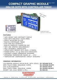
The EA <strong>DOGM</strong>132, a 132x32-pixel graphics display, is a new addition to ELECTRONIC ASSEMBLY’s EA <strong>DOGM</strong><br />
series. It, too, has pins that allow it to be mounted quickly and easily. 6 different optional LED backlights are available.<br />
These can be combined with 5 different display technologies, making it possible to have up to around 20 different designs.<br />
Designed for compact, handheld devices, this modern LCD series offers a number of benefits with and without<br />
backlighting:<br />
* Extremely compact (55x31 mm) with a large viewing area of 51x15 mm<br />
* Super-flat: 2.0 mm without backlight module, and only 5.8 mm with a b./l. module mounted<br />
* Serial SPI interface (4-wire)<br />
* Single supply +2.4 V or +3.3 V<br />
* Typical power consumption of only 140µA in full operation (white LED backlight from 5mA)<br />
* Easily mounted by soldering<br />
* Wide range of design variants orderable as single units<br />
* Backlighting color changes possible<br />
CONTRAST ADJUSTMENT<br />
The contrast can be set by means of a command for all the displays in the EA <strong>DOGM</strong> series. The contrast setting of<br />
the display must be set once by the software, and is then kept constant throughout the entire operating temperature<br />
range (-20..+70°C), thanks to the integrated temperature compensation.<br />
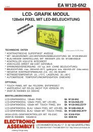
LED BACKLIGHT<br />
6 different variants are available for individual backlighting: white,<br />
yellow/green, blue, red, amber and a full-color version.<br />
There are 2 separate LED paths available for each monochrome<br />
backlight that can be switched in parallel or in series to suit the system<br />
voltage. This means that most backlights can be run at either 3.3 V or<br />
5 V.<br />
To operate the backlight, we recommend a current source (e.g.<br />
CAT4238TD) or an external series resistor to limit the current. This<br />
can be calculated from R=U/I; you can find the values in the table on<br />
the right. To prolong the life of the backlights, we recommend that you<br />
use a current source.<br />
The operating life of the yellow/green, red and amber backlights is<br />
100,000 hours. The life of the white and blue backlights is considerably<br />
shorter. We recommend that you dim these or switch them off<br />
whenever possible.<br />
Important: Never connect the backlight LEDs directly to a 5 V/<br />
3.3 V supply as this will immediately destroy the LEDs. Always<br />
use a current source. Please note that derating applies at<br />
temperatures exceeding +25°C.<br />
ASSEMBLING<br />
First, clip the display and backlight modules together by gently pushing<br />
the display pins through the corresponding holes on the backlight<br />
module. Then insert the entire module into the socket, or into the<br />
soldering holes on the pcb. The backlight pins (the 2 rows with 3 pins<br />
at the bottom) must be soldered on the top side as well to ensure good<br />
contact between the modules.<br />
yellow/green<br />
EA LED55x31-G<br />
Forwar<br />
voltage<br />
Important: The display has a protective film on the top and/or the bottom, and there is also one on the<br />
backlight. These must be removed.<br />
Make sure that neither display nor backlight will never come into contact with any kind of liquid like<br />
Fluxer, Cleaner, Water.<br />
Current<br />
max.<br />
Limiting resistor<br />
@ 3,3 V @ 5 V<br />
Connected in parallel 2,2 V 80 mA 14 ohm 35 ohm<br />
Connected in series 4,4 V 40 mA - 15 ohm<br />
white<br />
EA LED55x31-W<br />
Forwar<br />
voltage<br />
Current<br />
max.<br />
Limiting resistor<br />
@ 3,3 V @ 5 V<br />
Connected in parallel 3,2 V 60 mA 1,6 ohm 30 ohm<br />
Connected in series 6,4 V 30 mA - -<br />
blue<br />
EA LED55x31-B<br />
Forwar<br />
voltage<br />
Current<br />
max.<br />
Limiting resistor<br />
@ 3,3 V @ 5 V<br />
Connected in parallel 3,2 V 60 mA 1,6 ohm 30 ohm<br />
Connected in series 6,4 V 30 mA - -<br />
amber<br />
EA LED55x31-A<br />
Forwar<br />
voltage<br />
Current<br />
max.<br />
Limiting resistor<br />
@ 3,3 V @ 5 V<br />
Connected in parallel 2,4 V 80 mA 11 ohm 32 ohm<br />
Connected in series 4,8 V 40 mA - 5 ohm<br />
red<br />
EA LED55x31-R<br />
Forwar<br />
voltage<br />
Current<br />
max.<br />
Limiting resistor<br />
@ 3,3 V @ 5 V<br />
Connected in parallel 2,1 V 80 mA 15 ohm 36 ohm<br />
Connected in series 4,2 V 40 mA - 20 ohm<br />
Full color<br />
EA LED55x31-RGB<br />
Forwar<br />
voltage<br />
Current<br />
max.<br />
Limiting resistor<br />
@3,3 V @ 5 V<br />
Connected in parallel 4 V 125 mA - 3x24 ohm
ELECTRONIC ASSEMBLY reserves<br />
the right to change specifications<br />
without prior notice. Printing and<br />
typographical errors reserved.<br />
EA LED55x31-W<br />
White<br />
EA LED55x31-G<br />
Yellow/green<br />
EA LED55x31-B<br />
Blue<br />
EA <strong>DOGM</strong>132-5<br />
Page 3<br />
5 DIFFERENT TECHNOLOGIES<br />
See below for an overview of available technologies, combinations with available backlights and their usability:<br />
Display Technology Optional<br />
backlight<br />
EA <strong>DOGM</strong>132W<br />
FSTN pos.<br />
transflective<br />
EA <strong>DOGM</strong>132E<br />
STN pos.<br />
yellow/green<br />
transmissive<br />
EA <strong>DOGM</strong>132B<br />
STN neg. blue<br />
transmissive<br />
EA <strong>DOGM</strong>132S<br />
FSTN neg.<br />
transmissive<br />
EA <strong>DOGM</strong>132L<br />
STN pos.<br />
yellow/green<br />
reflective<br />
usage is possible<br />
with and without<br />
backlight module<br />
backlight module is<br />
necessary<br />
backlight module is<br />
necessary<br />
backlight module is<br />
necessary<br />
no backlight<br />
possible<br />
Readability<br />
even without<br />
backlight<br />
readable<br />
even without<br />
backlight<br />
readable<br />
Display color<br />
non<br />
backlighted<br />
black on white<br />
dark green on<br />
yellow/green<br />
--- ---<br />
--- ---<br />
good at<br />
"normal"<br />
ambient<br />
brightness<br />
dark green on<br />
yellow/green<br />
EA LED55x31-R<br />
Red<br />
Display color<br />
with backlight<br />
black on backlight<br />
color<br />
black on<br />
yellow/green<br />
backlight color on<br />
blue~black<br />
background<br />
backlight color on<br />
black background<br />
EA LED55x31-A<br />
Amber<br />
Required<br />
backlight<br />
white, blue,<br />
amber, RGB<br />
yellow/green<br />
white,<br />
yellow/green<br />
white, amber,<br />
RGB<br />
--- ---<br />
6 AND MORE DIFFERENT BACKLIGHTS<br />
6 and more different backlight colors are available to match equipments design as much as possible. The<br />
most effective and brightest one is the white one EA LED55x31-W.<br />
EA LED55x31-RGB<br />
Full Color<br />
If you see black and white pictures on this page but you want to see the colors of the displays, you can download a<br />
full-colored version of this document at<br />
http://www.lcd-module.de/eng/pdf/grafik/dogm132-5e.pdf
EA <strong>DOGM</strong>132-5<br />
Page 4<br />
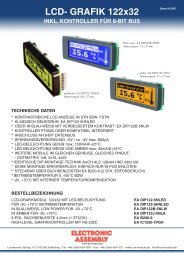
APPLICATION EXAMPLES<br />
WIDE RANGE<br />
The operation on +2.4..+3.3V (single<br />
supply) requires 9 external capacitors.<br />
Current consumption is typ. 150uA.<br />
ELECTRONIC ASSEMBLY reserves<br />
the right to change specifications<br />
without prior notice. Printing and<br />
typographical errors reserved.<br />
LOW POWER<br />
+3.0V or +3.3V (single supply) operation<br />
requires 8 external capacitors. Current<br />
consumption typ. 110uA<br />
LOW VOLTAGE<br />
If an external source of +9..+12V (does not<br />
have to be stabilized) is available, the charge<br />
pump is not needed and less external<br />
components are required. Supply and logic<br />
voltage may be 1.8..3.3V
ELECTRONIC ASSEMBLY reserves<br />
the right to change specifications<br />
without prior notice. Printing and<br />
typographical errors reserved.<br />
TABLE OF PROGRAMMING COMMANDS<br />
EA <strong>DOGM</strong>132-5<br />
Page 5<br />
DATA TRANSFER<br />
Data transfer is unidirectional. That means that data can only be written; it cannot be read again. In contrast<br />
to other displays, a busy query is not necessary with this display. The clock-pulse rate of the SCL line can<br />
be up to 20 MHz @3.3V, depending on the supply voltage. You will find more detailed information on timing on<br />
pages 64 and 65 of the data sheet of the ST7565R controller, which you will find on our website at<br />
http://www.lcd-module.de/eng/pdf/zubehoer/st7565r.pdf
EA <strong>DOGM</strong>132-5<br />
Page 6<br />
INITIALISATION EXAMPLE<br />
Using the internal voltage converter (single supply +2.4V ..+3.3V).<br />
Applications „LOW POWER“ and „WIDE RANGE“<br />
Initialisation example for single supply (bottom view)<br />
Command A0 D7 D6 D5 D4 D3 D2 D1 D0 Hex Remark<br />
(2) Display start line set 0 0 1 0 0 0 0 0 0 $40 Display start line 0<br />
(8) ADC set 0 1 0 1 0 0 0 0 1 $A1 ADC reverse *)<br />
(15) Common output mode select 0 1 1 0 0 0 0 0 0 $C0 Normal COM0~COM31<br />
(9) Display normal/reverse 0 1 0 1 0 0 1 1 0 $A6 Display normal<br />
(11) LCD bias set 0 1 0 1 0 0 0 1 0 $A2 Set bias 1/9 (Duty 1/33)<br />
(16) Power control set 0 0 0 1 0 1 1 1 1 $2F Booster, Regulator and Follower on<br />
(20) Booster ratio set 0<br />
1 1 1 1 1 0 0 0 $F8 Set internal Booster to 3x / 4x<br />
0 0 0 0 0 0 0 0 $00<br />
(17) V0 voltage regulator set 0 0 0 1 0 0 0 1 1 $23<br />
(18) <strong>Electronic</strong> volume mode set 0<br />
(19) Static indicator set 0<br />
1 0 0 0 0 0 0 1 $81<br />
0 0 0 1 1 1 1 1 $1F<br />
*) Make sure that for 6:00 viewing direction ADC has to be set to „reverse“ (mirrored layout) !<br />
INITIALISATION EXAMPLE<br />
Using an external power supply for contrast (dual power supply).<br />
Application „LOW VOLTAGE“<br />
*) Make sure that for 6:00 viewing direction ADC has to be set to „reverse“ (mirrored layout) !<br />
Contrast set<br />
1 0 1 0 1 1 0 0 $AC No indicator<br />
0 0 0 0 0 0 0 0 $00<br />
(1) Display ON/OFF 0 1 0 1 0 1 1 1 1 $AF Display on<br />
Initialisation example for dual power supply (bottom view)<br />
Command A0 D7 D6 D5 D4 D3 D2 D1 D0 Hex Remark<br />
(2) Display start line set 0 0 1 0 0 0 0 0 0 $40 Display start line 0<br />
(8) ADC set 0 1 0 1 0 0 0 0 1 $A1 ADC reverse *)<br />
(15) Common output mode select 0 1 1 0 0 0 0 0 0 $C0 Normal COM0~COM31<br />
(9) Display normal/reverse 0 1 0 1 0 0 1 1 0 $A6 Display normal<br />
(11) LCD bias set 0 1 0 1 0 0 0 1 0 $A2 Set bias 1/9 (Duty 1/33)<br />
(16) Power control set 0 0 0 1 0 1 0 1 1 $2B Booster off, Regulator, Follower on<br />
(17) V0 voltage regulator set 0 0 0 1 0 0 0 1 1 $23<br />
(18) <strong>Electronic</strong> volume mode set 0<br />
(19) Static indicator set 0<br />
1 0 0 0 0 0 0 1 $81<br />
0 0 0 1 1 1 1 1 $1F<br />
Contrast set<br />
1 0 1 0 1 1 0 0 $AC No indicator<br />
0 0 0 0 0 0 0 0 $00<br />
(1) Display ON/OFF 0 1 0 1 0 1 1 1 1 $AF Display on<br />
ELECTRONIC ASSEMBLY reserves<br />
the right to change specifications<br />
without prior notice. Printing and<br />
typographical errors reserved.<br />
Orientation for 6 o`clock (Bottom View)
ELECTRONIC ASSEMBLY reserves<br />
the right to change specifications<br />
without prior notice. Printing and<br />
typographical errors reserved.<br />
12:00 VIEWING ANGLE, TOP VIEW OPTION<br />
If the display is read mostly from above (on the front of a laboratory power<br />
supply unit, for example), the preferred angle of viewing can be set to 12<br />
o’clock. This rotaties the display by 180°. A slightly different initialization<br />
setup is required for this. Also keep in mind that the leftmost column<br />
(normally numbered as 0) will now change to 4.<br />
Initialisation example top view<br />
Command A0 D7 D6 D5 D4 D3 D2 D1 D0 Hex Remark<br />
(8) ADC set 0 1 0 1 0 0 0 0 0 $A0 ADC normal<br />
(15)<br />
Common output mode<br />
select<br />
0 1 1 0 0 1 0 0 0 $C8 Reverse COM31~COM0<br />
EA <strong>DOGM</strong>132-5<br />
Page 7<br />
USB-TEST BOARD EA 9780-1USB<br />
For easy startup, a USB test board is available that can be connected to a PC. A USB cable and Windows<br />
software is supplied with the product. This allows text and images (BMP) to displayed directly on the connected<br />
display. You will find more information on the test board in the EA 9780-1USB data sheet.<br />
SIMULATION WITH WINDOWS<br />
A simulator window also displays the contents of the display. The<br />
software can simulate all the displays and colors even without the<br />
hardware. You can download the software free from our website:<br />
http://www.lcd-module.de/deu/disk/startdog.zip<br />
Orientation for 12 o`clock (Top View)
EA <strong>DOGM</strong>132-5<br />
Page 8<br />
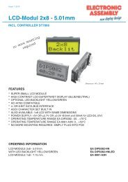
DIMENSIONS EA <strong>DOGM</strong>132<br />
Pin Symbol Level Function Pin Symbol Level Function<br />
1 NC (A1+: LED backlight) 21 V0 - LC Drive<br />
2 NC (C1-: LED backlight) 22 V1 - LC Drive<br />
3 23 V2 - LC Drive<br />
4 24 V3 - LC Drive<br />
5 25 V4 - LC Drive<br />
6 26 VSS L Power Supply 0V (GND)<br />
7 27 CAP2N - Voltage Converter<br />
8 28 CAP2P - Voltage Converter<br />
9 29 CAP1P - Voltage Converter<br />
10 30 CAP1N - Voltage Converter<br />
11 31 CAP3P - Voltage Converter<br />
12 32 VOUT - Voltage Output +9..12V<br />
13 33 VSS L Power Supply 0V (GND)<br />
14 34 VDD2 H Power Supply Booster<br />
15 35 VDD H Power Supply +1,8..3,3V<br />
16 36 SI H / L Serial Data In<br />
17 37 SCL H / L Serial Clock<br />
18 38 A0 H / L L= Command, H= Data<br />
19 NC (C2-: LED backlight) 39 RST L Reset (active low)<br />
20 NC (A2+: LED backlight) 40 CS1B L Chip Select (active low)<br />
DIMENSIONS EA LED55X31<br />
ELECTRONIC ASSEMBLY reserves<br />
the right to change specifications<br />
without prior notice. Printing and<br />
typographical errors reserved.<br />
all dimensions are in mm<br />
Note:<br />
- LC displays are generally not suited for wave or reflow<br />
soldering. Temperatures of over 80°C can cause<br />
lasting damage.<br />
- The surfaces of the displays and backlights are<br />
protected from scratching by self-adhesive protective<br />
foils. Please remove these before mounting.<br />
- Make sure that either display nor backlight will never<br />
come into contact with any kind of liquid like Fluxer,<br />
Cleaner, Water.<br />
Note:<br />
The 4 LED pins A1/A2 and<br />
C1/C2 also have to be<br />
soldered from above to ensure<br />
good contact.<br />
Zeppelinstrasse 19 · D-82205 Gilching · Phone +49-(0)8105-778090 · Fax: +49-(0)8105-778099 · www.lcd-module.de · info@lcd-module.de<br />
ATTENTION<br />
handling precautions!<br />
ATTENTION<br />
handling precautions!<br />
all dimensions are in mm