LCD-Modul 2x8 - 5.01mm - Electronic Assembly
LCD-Modul 2x8 - 5.01mm - Electronic Assembly
LCD-Modul 2x8 - 5.01mm - Electronic Assembly

You also want an ePaper? Increase the reach of your titles
YUMPU automatically turns print PDFs into web optimized ePapers that Google loves.
Issue 1.2013<br />
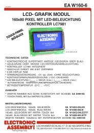
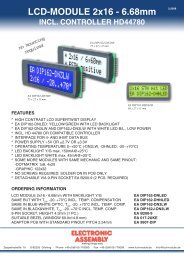
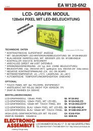
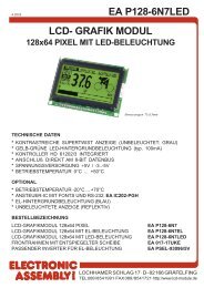
<strong>LCD</strong>-<strong>Modul</strong> <strong>2x8</strong> - <strong>5.01mm</strong><br />
INCL. CONTROLLER ST7066<br />
no more mounting<br />
required<br />
FEATURES<br />
* SUPER SMALL <strong>LCD</strong> MODULE<br />
* HIGH CONTRAST <strong>LCD</strong>-SUPERTWIST DISPLAY (BLUE/NEUTRAL)<br />
* OPTIONAL LED-BACKLIGHT YELLOW/GREEN<br />
* HD 44780 COMPATIBLE<br />
* 4- OR 8-BIT DATA BUS INTERFACE<br />
* ASCII CHARACTER SET BUILT IN<br />
* ALSO AVAILABLE: 1x8 <strong>LCD</strong> WITH SAME DIMENSIONS<br />
* POWER SUPPLY +5V OR ±2.7V OR ±3.3V @2mA and 50mA for LED-B/L (5V)<br />
* OPERATING TEMPERATURE RANGE EA DIPS082: -20…+70°C<br />
* OPERATING TEMPERATURE RANGE EA 8081-A3N: 0…+50°C<br />
* NO MORE MOUNTING REQUIRED: SIMPLY PLUG INTO PCB<br />
ORDERING INFORMATION<br />
Dimension 40 x 20 mm<br />
<strong>LCD</strong>-MODULE <strong>2x8</strong> - <strong>5.01mm</strong> EA DIPS082-HN<br />
WITH LED BACKLIGHT YELLOW/GREEN EA DIPS082-HNLED<br />
<strong>LCD</strong>-MODULE 1x8 - 7.15 mm EA 8081-A3N
Pinout<br />
Pin Symbol Level Function Pin Symbol Level Function<br />
1 VSS L Power Supply 0V (GND) 8 D1 H/L Display Data<br />
2 VDD H Power Supply +5V 9 D2 H/L Display Data<br />
3 VEE - Contrast (about 0.3V / 1.2V) 10 D3 H/L Display Data<br />
4 RS H/L H=Data / L=Command 11 D4 (D0) H/L Display Data<br />
5 R/W H/L H=Read / L=Write 12 D5 (D1) H/L Display Data<br />
6 E H Enable (falling edge) 13 D6 (D2) H/L Display Data<br />
7 D0 H/L Display Data / Anode LED-B/L 14 D7 (D3) H/L Display Data, MSB<br />
Table of commands<br />
Page 2<br />
Instruction<br />
RS R/W DB<br />
7<br />
DB<br />
6<br />
Code<br />
Clear Display 0 0 0 0 0 0 0 0 0 1<br />
Cursor At Home 0 0 0 0 0 0 0 0 1 *<br />
Entry Mode Set 0 0 0 0 0 0 0 1 I/D S<br />
Display On/Off<br />
Control<br />
DB<br />
5<br />
DB<br />
4<br />
DB<br />
3<br />
DB<br />
2<br />
DB<br />
1<br />
0 0 0 0 0 0 1 D C B<br />
Cursor / Display Shift 0 0 0 0 0 1 S/C R/L * *<br />
Function Set 0 0 0 0 1 DL N F * *<br />
CG RAM Address Set 0 0 0 1 ACG<br />
DD RAM Address Set 0 0 1 ADD<br />
Busy Flag / Address<br />
Read<br />
CG RAM / DD RAM<br />
Data write<br />
CG RAM / DD RAM<br />
Data Read<br />
0 1 BF AC<br />
Contrast setting<br />
DB<br />
Description<br />
0<br />
Clears all display and returns the cursor<br />
to the home position (Address 0).<br />
Returns the Cursor to the home<br />
position (Address 0). Also returns the<br />
display being shifted to the original<br />
position. DD RAM contents remain<br />
unchanged.<br />
Sets the Cursor move direction and<br />
specifies or not to shift the display.<br />
These operation are performed during<br />
data write and read.<br />
Sets ON/OFF of all display (D) cursor<br />
ON/OFF (C), and blink of cursor position<br />
character (B).<br />
Moves the Cursor and shifts the display<br />
without changing DD RAM contents.<br />
Sets interface data length (DL) number<br />
of display lines (N) and character font<br />
(F).<br />
Sets the CG RAM address. CG RAM<br />
data is sent and received after this<br />
setting.<br />
Sets the DD RAM address. DD RAM<br />
data is sent and received after this<br />
setting.<br />
Reads Busy flag (BF) indicating internal<br />
operation is being performed and reads<br />
address counter contents.<br />
<strong>2x8</strong> - <strong>5.01mm</strong><br />
LED Backlight<br />
Standard display EA DIPS082-HN is reflective, non-backlighted version. <strong>Modul</strong>e with part number<br />
EA DIPS082-HNLED comes with yellow/green LED backlight. Power consumption for backlight is 50mA<br />
typ. and 80mA max. Backlight is permanent switched on.<br />
For individual use LED backlight can be switched on and off after doing the following modification:<br />
Remove series resistor R5 and change resistor from R6 to R7. Now a positive voltage at pin 7 (D0)<br />
powers Anode of backlight direct. To limit LED-current an external series resistor is required (R Ext. =<br />
0,8V / I LED ). Please note that in this case display interface is 4-bit mode only !<br />
Execute<br />
Time<br />
(max.)<br />
1.64ms<br />
1.64ms<br />
40µs<br />
40µs<br />
40µs<br />
40µs<br />
40µs<br />
40µs<br />
1 0 Write Data Writes data into DD RAM or CG RAM 40µs<br />
1 1 Read Data Reads data from DD RAM or CG RAM 40µs<br />
Printing and typographical errors reserved.<br />
ELECTRONIC ASSEMBLY reserves the right to change specifications without prior notice.<br />
-
<strong>2x8</strong> - <strong>5.01mm</strong><br />
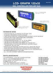
Character set<br />
Below shown character set is already built in. Additionally 8 self defined characters can be attached.<br />
CREATING YOUR OWN CHARACTERS<br />
All character display modules offered in this catalogue, are able to create 8 own characters (ASCII Codes 0..7) in<br />
addition to the 192 ROM fixed codes.<br />
1.) The command "CG RAM Address Set" defines the<br />
ASCII code (Bit 3,4,5) and the dot line (Bit 0,1,2)<br />
of the new character. Example demonstrates<br />
creating ASCII code $00.<br />
2.) Doing 8 times the write command "Data Write"<br />
defines line by line the new character. 8th. byte<br />
stands for the cursor line.<br />
3.) The new defined character can be used as a "normal"<br />
ASCII code (0..7); use with "DD RAM Address<br />
Set" and "Data Write".<br />
INITIALISATION FOR A 2 LINE DISPLAY / 8-BIT MODE<br />
Command RS R/ DB DB DB DB DB DB DB DB Remark<br />
Function Set 0 0 0 0 1 1 1 0 0 0 8-Bit Data Length, 2/4 lines, 5x7 Font<br />
Display ON/OFF 0 0 0 0 0 0 1 1 1 1 Display on, Cursor visible, Cursor blink<br />
Clear Display 0 0 0 0 0 0 0 0 0 1 Clear Display, Cursor Home<br />
Entry Mode Set 0 0 0 0 0 0 0 1 1 0 Cursor Auto-Increment<br />
Printing and typographical errors reserved.<br />
ELECTRONIC ASSEMBLY reserves the right to change specifications without prior notice.<br />
Adresse im CG RAM setzen Daten des Zeichens<br />
Adresse Hex<br />
7 6 5<br />
Bit<br />
4 3 2 1 0<br />
Hex<br />
0 0 0 $40<br />
0 0 1 0 0 $04<br />
0 0 1 $41 0 0 1 0 0 $04<br />
0 1 0 $42 0 0 1 0 0 $04<br />
0 1 0 0 0<br />
0<br />
1<br />
1<br />
0<br />
1<br />
0<br />
$43<br />
$44<br />
X X X<br />
0<br />
1<br />
0<br />
0<br />
1<br />
1<br />
0<br />
0<br />
0<br />
1<br />
$04<br />
$15<br />
1 0 1 $45 0 1 1 1 0 $0E<br />
1 1 0 $46 0 0 1 0 0 $04<br />
1 1 1 $47 0 0 0 0 0 $00<br />
Page 3
<strong>2x8</strong> - <strong>5.01mm</strong><br />
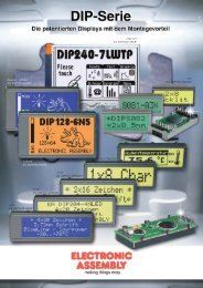
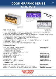
Dimensions<br />
all dimensions are in mm<br />
1-line Display EA 8081-A3N<br />
ELECTRONIC ASSEMBLY GmbH<br />
Zeppelinstraße 19<br />
D-82205 Gilching<br />
Germany<br />
Delivery state<br />
Intern, LED permanent on<br />
Fon: +49 (0)8105-7780 90<br />
Fax: +49 (0)8105-7780 99<br />
e-Mail: info@lcd-module.de<br />
Web: www.lcd-module.com<br />
Technische Änderung vorbehalten.<br />
Wir übernehmen keine Haftung für<br />
Druckfehler und Applikationsbeispiele.<br />
ATTENTION<br />
handling precautions!<br />
Extern, LED controllable,<br />
only possible in 4-bit mode