Workshop engine manual
Workshop engine manual
Workshop engine manual

You also want an ePaper? Increase the reach of your titles
YUMPU automatically turns print PDFs into web optimized ePapers that Google loves.
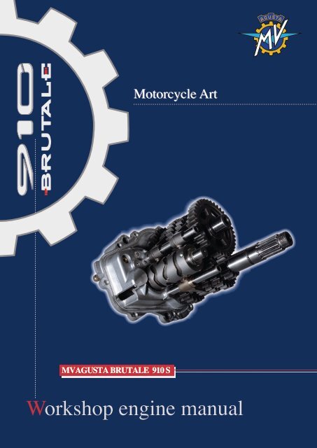
MVAGUSTA BRUTALE 910 S<br />
<strong>Workshop</strong> <strong>engine</strong> <strong>manual</strong>
© 2005<br />
The reproduction, even partial of this document is forbidden without prior written agreement of MV Agusta S.p.A.<br />
Part. N° 8A00A6440 - Edition N° 1<br />
Printed – December 2005
<strong>Workshop</strong> <strong>engine</strong> <strong>manual</strong><br />
MVAGUSTA BRUTALE F4 910 S
Statement<br />
This <strong>manual</strong>, to be used by the MV Agusta authorised workshops has been realised with the<br />
purpose of assisting authorised personnel in maintenance and repairs operations of the<br />
motorcycle. The knowledge of technical data herein noted, determines the complete professional<br />
training of the technician.<br />
With purpose of making the reading of this <strong>manual</strong> immediately comprehensible, the paragraphs<br />
have been aligned with detailed illustrations that highlight the argument dealt with.<br />
Useful advice<br />
To prevent any problems and to reach an excellent final result, MV Agusta recommends<br />
keeping to the following guidelines:<br />
- In the case of an eventual repair, evaluate the client’s impressions who states that there<br />
is an abnormal functioning of the motorcycle and to formulate the right questions to<br />
clarify the symptoms of the problem.<br />
- Clearly diagnose the cause of the abnormality. The basic fundamental theories can be<br />
absorbed by reading this <strong>manual</strong> that must necessarily be integrated to the personal<br />
experience and the participation of training courses that are periodically organised by<br />
MV Agusta.<br />
- Rationally plan the repair to avoid slack periods, e.g. the collection of spare parts, the<br />
preparation of tools and equipment, etc.<br />
- To reach the part to be repaired limiting the work to the essential operations.<br />
With regards to this, a valid help would be to consult this <strong>manual</strong> with regards to the<br />
sequences of removal demonstrated in this <strong>manual</strong>.<br />
Informative note<br />
MV Agusta S.p.A. is committed to a policy of continuous improvement of their products. For<br />
this reason, there could be slight differences between that which is written here and the<br />
motorcycle on which repairs and/or maintenance are about to be carried out. MV Agusta<br />
models are exported to many countries where different norms in relation to the highway<br />
code and homologation procedures are valid. Hoping that you will comprehend these problems,<br />
MV Agusta S.p.A. reserves the right to make modifications to its products and technical<br />
documentation at any moment and without prior announcement.<br />
Respect and defend the environment<br />
Everything that we do has repercussions on the entire planet and its resources.<br />
MV Agusta, wanting to protect the interest of the people, would like to make the client and<br />
the technicians of the technical assistance centres aware and to adopt modalities of use of<br />
the motorcycle and the disposure of its parts in full respect of the norms in force in terms of<br />
environmental pollution, disposal and the recycling of waste.<br />
- 2 -
Freni General Index<br />
GENERAL DESCRIPTION ........................................................................................<br />
ENGINE ....................................................................................................................<br />
- 3 -<br />
A<br />
B
General description<br />
- 1 -<br />
SECTION A<br />
Revision 0<br />
A
General description<br />
A SUMMARY<br />
HOW TO CONSULT THIS MANUAL . . . . . . . . . . . . . . . . . . . . . . . . . . . . . . . . . . . . . . . . . . . . . . . . . . . . .PAGE 3<br />
THE PURPOSE OF THIS MANUAL . . . . . . . . . . . . . . . . . . . . . . . . . . . . . . . . . . . . . . . . . . . . . . . . . . . . .PAGE 3<br />
GLOSSARY AND SYMBOLS . . . . . . . . . . . . . . . . . . . . . . . . . . . . . . . . . . . . . . . . . . . . . . . . . . . . . . . . . . .PAGE 4<br />
RIGHT HAND AND LEFT HAND STANDARD . . . . . . . . . . . . . . . . . . . . . . . . . . . . . . . . . . . . . . . . . . . . .PAGE 6<br />
SAFETY . . . . . . . . . . . . . . . . . . . . . . . . . . . . . . . . . . . . . . . . . . . . . . . . . . . . . . . . . . . . . . . . . . . . . . . . . . .PAGE 7<br />
WARNING . . . . . . . . . . . . . . . . . . . . . . . . . . . . . . . . . . . . . . . . . . . . . . . . . . . . . . . . . . . . . . . . . . . . . . . . . .PAGE 9<br />
INDEX . . . . . . . . . . . . . . . . . . . . . . . . . . . . . . . . . . . . . . . . . . . . . . . . . . . . . . . . . . . . . . . . . . . . . . . . . . . . .PAGE 9<br />
OPERATIVE TECHNICAL SPECIFICATIONS . . . . . . . . . . . . . . . . . . . . . . . . . . . . . . . . . . . . . . . . . . . . .PAGE 10<br />
- 2 -
HOW TO CONSULT THIS MANUAL<br />
General description<br />
Order of the subjects<br />
This <strong>manual</strong> is divided into chapters that deal with the<br />
sub-groups of the motorcycle.<br />
To quickly find the chapter required, the pages of each<br />
chapter are marked with a reference mark aligned to<br />
the relative item in the general index.<br />
Display of the operations<br />
The operations of disassembly, assembly, removal and control are presented with the help of illustrations (designs and<br />
photographs).<br />
The illustrations contain symbols that indicate the procedure, special tools and other information. See the symbols lists<br />
for their significance.<br />
The procedures are described step after step.<br />
EXAMPLE<br />
Steering pin tightening<br />
Screw in the steering pin flange ring, without tightening.<br />
This operation must be done <strong>manual</strong>ly.<br />
Check that the steering base is at the end of its travel,<br />
to the right.<br />
Using the special tool N. 800091645, tighten the ring<br />
(1) by rotating it 10° calculated approximately as one<br />
third of the movement between the two holes of the<br />
ring (2) of the steering head (see the figure).<br />
PURPOSE OF THE MANUAL<br />
Principally, this <strong>manual</strong> has been written for MV Agusta dealers and qualified mechanics.<br />
It is not possible to document all the knowledge necessary for a mechanic in a <strong>manual</strong>. Those who utilise it must have<br />
a basic knowledge of mechanical concepts and the inherent procedures in the techniques of repairing motorcycles.<br />
Without this knowledge, The maintenance and repair operations can render the motorcycle unsafe for use.<br />
Updates<br />
MV Agusta S.p.A. is committed to a policy of continuous updating of the models produced. The modifications and significant<br />
changes to the specifications and the procedures will be communicated to the official dealers and will appear<br />
in future editions of this <strong>manual</strong>.<br />
All information, instructions and technical data included in this <strong>manual</strong> are based upon information on the product<br />
updated at the moment of going to print. MV Agusta S.p.A. reserves the right to carry out changes at any moment without<br />
prior notice and without incurring any obligation.<br />
- 3 -<br />
2<br />
1<br />
10°<br />
A
A GLOSSARY AND SYMBOLS<br />
ATTENTION<br />
WARNING<br />
WARNING<br />
General description<br />
During this kind of procedure<br />
inflammable vapours<br />
might develop and metallic<br />
parts might be expelled at<br />
high velocity. Thus, it is necessary<br />
to:<br />
- work far from exposed<br />
flames and sparks;<br />
- wear protective clothing;<br />
- wear protective eyeglasses.<br />
In case it should be necessary,<br />
due to wear, to substitute<br />
a particular, relative to<br />
a cylinder, we strongly suggest<br />
that you check and if<br />
necessary, substitute the<br />
same particular in all of the<br />
cylinders for more satisfying<br />
results.<br />
In particular, we recommend<br />
that at the same time<br />
you substitute:<br />
- pistons with relative elastic<br />
bands and piston pins;<br />
- valves with relative<br />
springs, semi-cones,<br />
disks and grazings;<br />
- Valve guides with relative<br />
valves, springs, semicones<br />
and grazings;<br />
- bed bearing;<br />
- whatever else undergoes<br />
uniform wear, aside from<br />
the position of the relative<br />
cylinder.<br />
In order to allow the motor<br />
to function under the best<br />
conditions, it is necessary<br />
that all of the couplings are<br />
within the accepted tolerances<br />
established. A tight<br />
coupling, is in fact, cause<br />
for seizure as soon as the<br />
organs in motion begin to<br />
heat, while a loose coupling<br />
is cause for vibrations<br />
which accelerates wear on<br />
the particulars in motion.<br />
- 4 -<br />
N.B.<br />
N.B.<br />
All of the countersigns indicting right,<br />
left, superior, inferior, front and back,<br />
refer to the motor-bike in the normal<br />
direction of march.<br />
The motor supports numbering of the<br />
cylinders and of the attached components,<br />
increases moving from left<br />
towards right in regards to the direction<br />
of march.<br />
This symbol indicates the "procedure to<br />
be carried out with the motor removed<br />
from the motor-bike".<br />
This symbol indicates "the procedures<br />
to be carried out with an empty cooling<br />
circuit".<br />
Utilise a specific tool or equipment for<br />
the correct carrying out of the operation<br />
described.<br />
Tighten to the specified torque.<br />
Tolerance or limit of use.<br />
Utilise the tester.
Use the recommended oil.<br />
Use the recommended grease.<br />
General description<br />
Use the recommended brake fluid.<br />
Use the recommended suspension fluid.<br />
Use the recommended coolant.<br />
Use the recommended thread-locking<br />
fluid.<br />
- 5 -<br />
Use the recommended sealant.<br />
Use the recommended adhesive.<br />
Carry out accurate cleaning.<br />
Use new components.<br />
Substitute the component.<br />
Do not leave litter about.<br />
A
A<br />
General description<br />
RIGHT HAND AND LEFT HAND STANDARD<br />
To clarify the right hand and left hand standard that is used in this <strong>manual</strong>, herewith below is a diagram of the<br />
motorcycle and the <strong>engine</strong> against which are indicated the right and left sides.<br />
Right side<br />
Left side<br />
- 6 -<br />
Right side<br />
Cylinder 3<br />
Cylinder 2<br />
Cylinder 4 Cylinder 1<br />
Left side
SAFETY<br />
ATTENTION<br />
General description<br />
The information contained in this paragraph is fundamental so that the operations carried<br />
out on the motorcycle can be conducted with minimum risk to the mechanic.<br />
Carbon Monoxide<br />
• Exhaust gases contain carbon monoxide (CO) that is poisonous. Carbon monoxide can cause the loss of consciousness<br />
and death.<br />
• If it is necessary to switch on the <strong>engine</strong>, check that the environment is well ventilated. Never switch on the <strong>engine</strong><br />
in an enclosed environment.<br />
• Switching on the <strong>engine</strong> can only be carried out in an enclosed environment when there are the appropriate devices<br />
for the evacuation of exhaust gases.<br />
Petrol<br />
• Petrol is extremely inflammable and under certain conditions can be explosive.<br />
• Keep sources of heat, sparks and flames away from the work area.<br />
• Always work in a well-ventilated area.<br />
• Never use petrol as a cleaning solvent. Generally, avoid handling it unless it is absolutely necessary.<br />
• Do not use petrol for cleaning components by using compressed air.<br />
• Keep petrol out of reach of children.<br />
Engine oil<br />
• Engine oil can cause skin illnesses if in constant and long contact with the skin.<br />
• If the skin comes into contact with <strong>engine</strong> oil, wash the parts affected as soon as possible with soap and water.<br />
• If <strong>engine</strong> oil comes into contact with the eyes, rinse abundantly with water and seek medical attention.<br />
• If <strong>engine</strong> oil is swallowed, do not provocate vomiting to avoid the aspiration of the product into the lungs. Transport<br />
the injured person immediately to hospital.<br />
• Used oil contains dangerous substances and poisonous for the environment. To substitute oil, it is necessary to be<br />
equipped to deal with the collection of used oil in respect of the norms in force.<br />
• Do not dispose of used oil in the environment.<br />
• Keep used oil out of the reach of children.<br />
Engine coolant<br />
• Under certain situations, the ethylene glycol contained in the <strong>engine</strong> coolant is inflammable and its flame is invisible.<br />
Ethylene glycol would cause serious burns if ignited because it is invisible.<br />
• Avoid bringing the <strong>engine</strong> coolant into contact with hot parts. Such parts could be sufficiently hot to ignite the coolant.<br />
• The <strong>engine</strong> coolant (ethylene glycol) can cause irritation of the skin and is poisonous if swallowed.<br />
• If the <strong>engine</strong> coolant comes into contact with the skin, immediately remove any contaminated clothing and wash with<br />
soap and water. If it comes into contact with the eyes, abundantly rinse with clean water and immediately consult a<br />
doctor. If swallowed, do not provocate vomiting to avoid the aspiration of the product into the lungs. Administer clean<br />
water and transport the injured person immediately to hospital and show the product to the doctor.<br />
• If exposed to high concentrations of vapour, transport the injured person to a non-poisonous atmosphere and if necessary<br />
call a doctor.<br />
• Do not remove the radiator cap when the <strong>engine</strong> is still hot. Being under pressure, the <strong>engine</strong> coolant can be violently<br />
ejected and therefore provocate burns.<br />
• The <strong>engine</strong> coolant contains dangerous and poisonous substances and is therefore dangerous for the environment.<br />
To substitute used <strong>engine</strong> coolant, it is necessary to be equipped to deal with the collection of used oil/of used <strong>engine</strong><br />
coolant in respect of the norms in force.<br />
• Do not dispose of <strong>engine</strong> coolant in the environment.<br />
• Keep <strong>engine</strong> coolant out of reach of children.<br />
- 7 -<br />
A
A<br />
General description<br />
Brake fluid<br />
• Brake fluid is extremely corrosive.<br />
• Avoid any contacts with the eyes, skin and the mucous membrane.<br />
• If brake liquid comes into contact with the skin, remove all contaminated clothing and wash immediately with soap<br />
and water.<br />
• If brake fluid comes into contact with the eyes, abundantly rinse with water and call a doctor.<br />
• If swallowed, do not provocate vomiting to avoid aspiration of the product into the lungs. Immediately call a doctor.<br />
• Take the injured person immediately to hospital, if he has breathed brake fluid into the lungs.<br />
• In the case of exposure to high concentrations of vapour, move the injured person to a non-poisonous atmosphere<br />
and if necessary call a doctor.<br />
• In the case of accidental contact, rinse abundantly with water and call a doctor.<br />
• Keep brake fluid out of reach of children.<br />
Thread-locking fluid<br />
• As it is not classified as dangerous, the prolonged contact with the skin, particularly with regards to abrasions can<br />
provocate sensitiveness and dermatitis. In the case of contact with the skin, rinse abundantly with running water.<br />
• Move the injured person into the open air and call a doctor if the injured person feels ill after having breathed in the<br />
product.<br />
• In the case of contact with the eyes, rinse abundantly with water for at least 15 minutes.<br />
• If the thread-locking fluid has been swallowed, drink an abundant quantity of water or milk. Do not provocate vomiting<br />
to avoid the aspiration of the product into the lungs. Immediately call a doctor.<br />
• Keep out of reach of children.<br />
Nitrogen - rear shock absorber<br />
• The rear shock absorber contains nitrogen under pressure.<br />
• Before disposing of used shock absorbers, discharge the nitrogen via the depressurising valve.<br />
• Utilise only nitrogen to pressurise the shock absorber. The use of unstable gases can cause explosions that could<br />
cause burns.<br />
• Do not place the shock absorber near to flames or sources of heat as this could cause explosions with consequent<br />
burns.<br />
• Keep out of reach of children.<br />
Battery<br />
• The battery produces explosive gases. Keep it away from sparks, flames or cigarettes. During recharging, adequately<br />
ventilate the environment.<br />
• The battery contains a solution of sulphuric acid (electrolyte).<br />
• Sulphuric acid is corrosive and it destroys many materials and clothing. On contact with small quantities of water it<br />
generates a violent reaction that manifests itself by creating large quantity of heat and spurts of hot acid. Sulphuric<br />
acid attacks many metals thereby liberating hydrogen: an inflammable gas that forms an explosive mixture when<br />
mixed with air.<br />
• Contact with sulphuric acid can cause burns. In the case of contact, remove immediately all contaminated clothing<br />
and wash the skin with abundant quantities of water. Take the injured person to hospital if necessary.<br />
• In the case of contact with the eyes, rinse immediately with abundant water. Call a doctor and continue with the treatment<br />
until the doctor arrives.<br />
• If the electrolyte is swallowed, rinse the mouth with water without swallowing. Take the injured person immediately<br />
to hospital and explain to the doctor there what the injured person has swallowed.<br />
• The battery contains dangerous substances that are poisonous for the environment. It is necessary to be equipped<br />
to dispose of this product in respect of the norms in force.<br />
• Do not dispose of used batteries in the environment.<br />
• Keep out of reach of children.<br />
Hot parts<br />
• The <strong>engine</strong> and the exhaust system become very hot and maintain this temperature for some time after the <strong>engine</strong><br />
has been switched off. Wait for these parts to cool down before handling them or working on the motorcycle near to<br />
them. Use protective gloves.<br />
- 8 -
WARNING<br />
GENERAL INDEX<br />
General description<br />
The information contained in this<br />
WARNING<br />
paragraph is important so that the<br />
operations carried out on the motorcycle<br />
can be conducted without damaging the motorcycle.<br />
• Thoroughly clean the motorcycle before disassembling it.<br />
• During disassembly, clean all parts and place them in containers<br />
respecting exactly the order of disassembly.<br />
• Always use the special utensils where necessary and<br />
each time where prescribed.<br />
• Always use adhesives, sealants and lubricants where prescribed.<br />
Respect the instructions about their technical<br />
characteristics.<br />
• Always substitute parts such as gaskets, O-rings, security<br />
washers with new parts.<br />
• Slackening or tightening nuts or screws, always start with<br />
those of a greater dimension or from the centre. Always<br />
respect the torque values indicated.<br />
• Utilise only MV Agusta spare parts.<br />
INDEX<br />
GENERAL DESCRIPTION<br />
ENGINE .................<br />
General Index<br />
- 9 -<br />
SUMMARY OF EACH CHAPTER<br />
General description<br />
SUMMARY<br />
HOW TO CONSULT THIS MANUAL ................................................................................................................PAGE 3<br />
THE PURPOSE OF THIS MANUAL..................................................................................................................PAGE 3<br />
GLOSSARY AND SYMBOLS ...........................................................................................................................PAGE 4<br />
RIGHT HAND AND LEFT HAND STANDARD..................................................................................................PAGE 6<br />
SAFETY .............................................................................................................................................................PAGE 7<br />
OBSERVATIONS ..............................................................................................................................................PAGE 9<br />
INDEX.................................................................................................................................................................PAGE 9<br />
OPERATIVE TECHNICAL SPECIFICATIONS..................................................................................................PAGE 10<br />
A
A<br />
General description<br />
OPERATIVE TECHNICAL SPECIFICATIONS<br />
MOTORCYCLE IDENTIFICATION<br />
The registration number of the motorcycle is stamped on the right side of the steering head.<br />
The <strong>engine</strong> registration number is stamped on the upper <strong>engine</strong> casing, near the forks.<br />
2) Engine registration number<br />
Below is an example of the designation of the frame registration number:<br />
Manufacturer identification<br />
Vehicle model<br />
Version<br />
MY<br />
Establishment<br />
Progressive frame number<br />
- 10 -<br />
1) Frame registration number<br />
3) Homologation date<br />
ZCG F4 11 ?? ? V ??????
Engine<br />
- 1 -<br />
SECTION B<br />
Revision 0<br />
B
B<br />
Engine<br />
SUMMARY<br />
TABLE OF CLAMPING TORQUES ..........................................................................................................PAG. 3<br />
PLANNED MAINTENANCE SCHEDULE ..................................................................................................PAG. 5<br />
THROTTLE BODY ADJUSTMENT AND TUNING........................................................................................PAG. 13<br />
CYLINDER HEAD ......................................................................................................................................PAG. 20<br />
DISTRIBUTION CONTROL UNITS............................................................................................................PAG. 24<br />
CYLINDER AND PISTON GROUP ............................................................................................................PAG. 44<br />
CLUTCH ....................................................................................................................................................PAG. 50<br />
GEAR AND GEAR CONTROL ..................................................................................................................PAG. 57<br />
ELECTRICAL COMPONENTS ..................................................................................................................PAG. 64<br />
OIL PUMP ..................................................................................................................................................PAG. 66<br />
WATER PUMP............................................................................................................................................PAG. 68<br />
STARTING..................................................................................................................................................PAG. 72<br />
MOTOR SHAFT..........................................................................................................................................PAG. 74<br />
BEDPLATE ................................................................................................................................................PAG. 76<br />
CAPS ..........................................................................................................................................................PAG. 77<br />
LUBRICATION COMPONENTS: OIL TUBING SUPPORT PLATE ..........................................................PAG. 86<br />
LUBRICATION COMPONENTS: OIL FILTER SUPPORT ........................................................................PAG. 87<br />
REPLACEMENT OF OIL FILTER ..............................................................................................................PAG. 90<br />
LUBRICATING COMPONENTS: OIL RADIATOR ....................................................................................PAG. 93<br />
- 2 -
Engine<br />
TABLE OF CLAMPING TORQUES<br />
DESCRIPTION N·m Thread blockers<br />
HEAD<br />
Camshaft and gear screws 21 strong<br />
Sliding block distribution screws 8 medium<br />
Stand screws 12<br />
Valve cap screws 8<br />
Chain tightening screws 8<br />
Chain tightening cap 12<br />
CLUTCH<br />
Clutch nut 140 medium<br />
Disk thrust plate screws 10<br />
GEAR SHIFT<br />
Pinion nut 140 medium<br />
Gear selection drum tightening screws 25 medium<br />
M6 gear control screws 8 medium<br />
BEDPLATE ACCESSORIES<br />
Alternator tightening screws 25<br />
Motor starter tightening screws 10<br />
Water pump tightening screws 8<br />
Neutral switch screws 10<br />
FREE WHEEL STARTING<br />
Flexible coupling generator control screws 25 medium<br />
Flexible coupling nut 55 strong<br />
Flange tightening screws together with free wheel 10 medium<br />
OIL CUP<br />
Oil cup tightening screws 10<br />
TIGHTENING TORQUES: CONVERSION FACTORS<br />
To convert a tightening torque, refer to the following table.<br />
N·m Kg·m ft·lbs<br />
N·m ------ 0,10197 0,7375<br />
Kg·m 9,807 ------ 7,233<br />
ft·lbs 1,3559 0,13826 ------<br />
- 3 -<br />
B
B<br />
Engine<br />
CLAMPING TORQUES TABLE<br />
DESCRIPTION N·m Thread blockers<br />
BEDPLATE<br />
Clutch cap M6 screws 8<br />
M6 bearing clamp screw 12 medium<br />
Extractable gear change cap M8 screws 25<br />
M6 torque screws 10<br />
M8 torque screws 25<br />
Plate screws for oil radiator connectors 10<br />
Support screws for oil filter 40<br />
Inlet/outlet connectors for radiator oil 30 medium<br />
CONNECTING ROD<br />
Cap screws (*)<br />
(*) See fitting notes<br />
- 4 -
Engine<br />
PLANNED MAINTENANCE SCHEDULE<br />
The following diagram shows the recommended planned maintenance intervals. Periodic maintenance is essential<br />
to keep the vehicle in perfect running order and to ensure optimum cost efficiency.<br />
WARNING<br />
Use shorter maintenance intervals if the vehicle is used in particularly harsh conditions.<br />
Let us help protect the environment<br />
Everything we do affects the entire planet and its resources. To protect the common interest, MV Agusta<br />
urges its customers and service operators to use the vehicles and dispose of their components in compliance<br />
with applicable regulations on environmental pollution control, waste disposal and recycling.<br />
Scheduled maintenance tables<br />
fFrequency Km (mi)<br />
0 1000<br />
(600)<br />
6000<br />
(3800)<br />
12000<br />
(7500)<br />
18000<br />
(11200)<br />
24000<br />
(14900)<br />
30000<br />
(18600)<br />
36000<br />
(22400)<br />
Coupon<br />
Pre-delivery A B C D E F G<br />
Description Procedure<br />
Motor oil Substitution ● ● ● ● ● ● ●<br />
At least every year<br />
Motor oil filter<br />
Substitution<br />
(Use only MV Agusta original<br />
● ● ● ● ● ● ●<br />
oil filter)<br />
Each time <strong>engine</strong> oil is renewed<br />
Cooling liquid Check / Top up ● ● ● ● ● ● ● ●<br />
Substitution Every two years<br />
Cooling system Check for leaks ● ● ● ● ● ● ● ●<br />
Electric fan Check operation ● ● ● ● ● ● ● ●<br />
Valves Check / Regulation ● ● ● ●<br />
Distribution chain Check ● ● ●<br />
Substitution ●<br />
Mobile distribution block Check / Substitution ● ● ●<br />
Substitution ●<br />
- 5 -<br />
Every time timing chain is replaced<br />
hain tightening block Check / Substitution ● ● ●<br />
Spark plugs Check / Substitution ● ● ● ●<br />
Substitution ● ● ●<br />
Fuel filter Substitution ● ● ●<br />
Throttle body Check / Regulation ● ● ● ● ● ● ●<br />
Air filter Check / Substitution ● ● ● ● ● ●<br />
Brakes and clutch liquid Level check ● ● ● ● ● ● ●<br />
Substitution ●<br />
At least every two years<br />
Brakes / Clutch Check operation ● ● ● ● ● ● ● ●<br />
Plant chexk ● ● ● ● ● ● ●<br />
Cleaning of contact lever /<br />
pump piston area<br />
● ● ● ● ● ● ● ●<br />
Prake pads<br />
( front + rear )<br />
Check / Substitution ● ● ● ● ● ● ●<br />
Fuel lines Check for defects and leaks ● ● ● ● ● ● ●<br />
Substitution At least every 3 years<br />
Throttle control Check operation ● ● ● ● ● ● ● ●<br />
Verify/adjust play ● ● ● ● ● ● ● ●<br />
Starter control Check operation ● ● ● ● ● ● ● ●<br />
B
B<br />
Frequency Km (mi)<br />
Coupon<br />
Description Procedure<br />
Engine<br />
0 1000 6000 12000 18000 24000 30000 36000<br />
(600) (3800) (7500) (11200) (14900) (18600) (22400)<br />
Pre-delivery-<br />
Transmissions and flexible controls Check / Regulation ● ● ● ● ● ● ● ●<br />
Check / Regulation ● ● ● ● ● ● ● ●<br />
Drive chain Lubrification ● ● ● ●<br />
Pinion / Stop washer<br />
Ring gear<br />
Substitution ● ● ●<br />
Check ● ● ● ●<br />
Substitution<br />
- 6 -<br />
● ● ●<br />
Every time drive chain is replaced<br />
Check ● ● ● ●<br />
Substitution<br />
● ● ●<br />
Comunque ad ogni sostituzione della catena di trasmissione<br />
Sprocket elastic coupling Check ● ● ●<br />
Head tube ring nut Check / Regulation ● ● ● ●<br />
Steering bearings<br />
Tyres<br />
Wheel rim Visual check<br />
Check / Regulation ● ● ● ●<br />
Lubrification ●<br />
Check pressure ● ● ● ● ● ● ● ●<br />
Check wear ● ● ● ● ● ● ●<br />
● ● ● ● ● ● ●<br />
Every time tyres are replaced<br />
● ● ● ● ●<br />
Check<br />
Front wheel bearings Every time tyres are replaced<br />
Substitution ●<br />
Side stand Check operation ● ● ● ● ● ● ● ●<br />
Side stand<br />
Check operation ● ● ● ● ● ● ● ●<br />
switch<br />
Cleaning of contact lever<br />
area with side stand<br />
● ● ● ● ● ● ● ●<br />
Rear wheel hub<br />
needle bearing<br />
Check / lubrfication<br />
● ●<br />
needle bearing<br />
Substitution / lubrfication<br />
●<br />
Big fork bearings Check / lubrification ●<br />
Big fork chain shoes Check / substitution ● ● ● ● ● ● ●<br />
Frame plate chain shoes Check / substitution ● ● ● ● ● ● ●<br />
Rear damper Check / Regulation ● ● ● ●<br />
Front fork oil Substitution ●<br />
Battery connections Check and cleaning ● ● ● ● ● ● ●<br />
Electric system Check operation ● ● ● ● ● ● ● ●<br />
Meter assy. combination Check operation ● ● ● ● ● ● ● ●<br />
Lights / visual signals Check operation ● ● ● ● ● ● ● ●<br />
Claxon Check operation ● ● ● ● ● ● ● ●<br />
Front head light<br />
A B C D E F G<br />
Check operation ● ● ● ● ● ● ● ●<br />
Regulation Every time vehicle geometry is altered<br />
Starter switch Check operation ● ● ● ● ● ● ● ●<br />
Locks Check operation ● ● ● ● ● ● ● ●<br />
Tightening of screws and nuts Check / Tighten ● ● ● ● ● ● ● ●<br />
Hose clamps Check / Tighten ● ● ● ● ● ● ● ●<br />
General lubrication ● ● ● ● ● ● ● ●<br />
General test ● ● ● ● ● ● ● ●
Table of lubricants and fluids<br />
Engine<br />
Description Recommended product Specifications<br />
Engine lubrication oil AGIP RACING 4T 10W/60 (*) API SJ SAE 10W/60<br />
- 7 -<br />
Ethylene glycol<br />
Cooling liquid AGIP ECO - PERMANENT diluted with 40 per cent<br />
distilled water<br />
Clutch and brake fluid AGIP BRAKE FLUID DOT4 DOT4<br />
Chain oil MOTUL CHAIN LUBE ROAD –<br />
* : MV Agusta recommends purchasing the product from its authorized dealers. The <strong>engine</strong> oil AGIP Racing 4T<br />
10W/60 has been specially designed for the F4 <strong>engine</strong>. Should this lubricant be unavailable, MV Agusta recommends<br />
using fully synthetic oils complying with or exceeding the following specifications:<br />
– API SJ<br />
– ACEA A3<br />
– JASO MA<br />
– SAE 20 W-50 o 10 W-60<br />
NOTE<br />
The above specifications are to be found, alone or in combination<br />
with others, on the lubricating oil container.<br />
Motor oil<br />
SAE 10 W-60<br />
API SJ<br />
ACEA A3<br />
JASO MA<br />
B
B<br />
ITEM<br />
VALVES<br />
Ø Sealing external diameter<br />
Exhaust..............................<br />
Inlet....................................<br />
Sealing face thickness......<br />
Stem-guide clearance<br />
Exhaust..............................<br />
Inlet....................................<br />
Ø Guide internal diameter.......<br />
Valve stem<br />
Exhaust..............................<br />
Inlet....................................<br />
Valve spring<br />
Internal...............................<br />
External..............................<br />
Valve-cam clearance<br />
Exhaust..............................<br />
Inlet....................................<br />
Engine<br />
+0,3<br />
24,6 mm<br />
0<br />
+0,3<br />
28,6 0 mm<br />
+0,2<br />
1 mm<br />
-0,3<br />
STANDARD<br />
0,02 ÷ 0,04 mm.........................<br />
0,01 ÷ 0.03 mm.........................<br />
+0<br />
4,5 mm...........................<br />
+0,012<br />
4,475 ± 0,005 mm.....................<br />
4,485 ± 0,005 mm.....................<br />
33,8 mm....................................<br />
37,9 mm....................................<br />
0,20 ÷ 0,29<br />
0,15 ÷ 0,24<br />
- 8 -<br />
WEAR LIMIT<br />
Coupling : 0,10 mm<br />
4,55 mm<br />
4,445 mm<br />
4,455 mm<br />
33,3 mm<br />
37,4 mm<br />
0,08 mm
ITEM<br />
CYLINDER AND PISTON<br />
Piston ovalization...................<br />
Piston-cylinder play................<br />
Piston-pin play........................<br />
Pin-foot connecting rod play.....<br />
Segment thickness<br />
1 st ......................................<br />
2 nd ......................................<br />
Oil scraper.........................<br />
Maximum segment-cylinder play<br />
CLUTCH<br />
1 st ......................................<br />
2 nd ......................................<br />
Scraper.............................<br />
Disk thickness........................<br />
Springs...................................<br />
Engine<br />
STANDARD<br />
...................................................<br />
0,038 ÷ 0,067 mm<br />
0,004 ÷ 0,012 mm<br />
0,015 ÷ 0,032 mm<br />
-0,01<br />
0,8 mm...........................<br />
-0,03<br />
0<br />
0,8 mm...........................<br />
-0,02<br />
-0,03<br />
1,5 mm...........................<br />
-0,08<br />
0,2÷ 0,4 mm.............................<br />
0,2 ÷ 0,4 mm.............................<br />
0,2 ÷ 0,7 mm.............................<br />
3 mm.........................................<br />
..................................................<br />
- 9 -<br />
0,015 mm<br />
0,10 mm<br />
0,03 mm<br />
0,06 mm<br />
0,75 mm<br />
0,75 mm<br />
1,38 mm<br />
0,6 mm<br />
0,6 mm<br />
1 mm<br />
2,8 mm<br />
57,9 mm<br />
WEAR LIMIT<br />
B
B<br />
GEAR SHIFT<br />
ITEM<br />
Gear fork-groove pivot play..........<br />
Drum pit width.........................<br />
Ø fork pivot.............................<br />
Minimum idle gear<br />
axial play.................................<br />
Maximum gear fork play........<br />
Gear limit<br />
Primary...............................<br />
Secondary..........................<br />
Fork selection gear limit<br />
Primary (5a - 6a)..............<br />
Secondary (1a-2a, 3a-4a).<br />
Fork – pit play.........................<br />
BEDPLATE – DRIVE SHAFT<br />
Bed bearing<br />
functioning play.......................<br />
Connecting rod bearing<br />
Functioning play......................<br />
Drive shaft axial play...............<br />
Engine<br />
STANDARD<br />
0,35 ÷ 0,15 mm.........................<br />
7,05 ÷ 7,15 mm.......................<br />
6,8 ÷ 6,9 mm.............................<br />
0,10 mm<br />
...................................................<br />
...................................................<br />
...................................................<br />
...................................................<br />
...................................................<br />
0,2 ÷ 0,3 mm<br />
0,012 ÷ 0,038 mm.....................<br />
0,036 ÷ 0,061 mm.....................<br />
0,2 mm<br />
- 10 -<br />
0,65 mm<br />
7,35 mm<br />
6,7 mm<br />
0,7 mm<br />
5,6 mm<br />
4,6 mm<br />
4,65 mm<br />
3,65 mm<br />
0,7<br />
0,06 mm<br />
0,08 mm<br />
WEAR LIMIT
Engine<br />
Cleaning the parts<br />
All of the parts must be cleaned with special<br />
biodegradable solvents and dried with compressed air.<br />
Proceed with the cleaning process of all the parts<br />
before disassembling them as well as after the particular<br />
parts have been disassembled. Clean each part<br />
even before reassembling.<br />
Connections<br />
In order to allow the motor to function in the best conditions<br />
it is absolutely necessary that all of the connections<br />
meet the standards established by the manufacturer.<br />
A connection with reduced standards could<br />
cause seizing, while a connection with excessive toleration<br />
causes vibrations which accelerate the wear of<br />
the components.<br />
General norms for assembling the parts<br />
For reassembling invert the disassembling procedure,<br />
paying careful attention to the specified procedures.<br />
Gaskets, oil spill protector, metallic locks. Tightening<br />
rings in deformable material and self blocking nuts<br />
must always be substituted.<br />
The bearings are dimensioned for a determined number<br />
of working hours. Substitution is therefore recommended<br />
in consideration of the difficulty in checking<br />
wear. The above mentioned is in addition suggested<br />
for dimensional controls of the single components<br />
mentioned in the relative paragraphs.<br />
It is absolutely necessary to carefully clean all of the<br />
components; the bearings and all of the other parts<br />
subject to wear must be lubricated with motor oil before<br />
reassembling. Nuts and screws must be locked to the<br />
pre established torques.<br />
Following are the descriptions of the disassembling,<br />
revision and reassembling procedures of the various<br />
parts and sub parts constituting the motor, in the finalized<br />
sequence of a completely disassembled motor.<br />
Disassemble the motor from its frame as described in<br />
the relative paragraph;<br />
Drain the oil from the oil cup;<br />
Remove the spark plugs covering the openings with<br />
clean rags to avoid small objects (rings, etc.) from<br />
falling into the motor.<br />
- 11 -<br />
B
B<br />
Measuring compression in the cylinder<br />
The following tools are necessary in order to carry out<br />
this procedure:<br />
Spark plug key: n° 800089013<br />
Compression measurer<br />
Adapter for the compression measurer.<br />
A) Heat the motor to the usual functioning tem<br />
perature (of regime);<br />
B) Switch off the <strong>engine</strong>, remove the tank, air box<br />
and sparkplugs;<br />
C) Measure cylinder compression.<br />
Drag the motor into rotation by means of the starting<br />
motor with the butterfly valve completely open until the<br />
compression measurer indicator (compessionmeter)<br />
no longer rises; the compression measurement<br />
obtained is the maximum.<br />
NOTE<br />
Be sure the battery is completely charged.<br />
- Repeat the procedure for the other cylinders.<br />
Engine<br />
Cylinder compression control (280 rpm-min.)<br />
Motore Tipo Press. Min (bar) Press. Max (bar)<br />
910 S 7,5 14<br />
N.B.: If the compression in the cylinder is lower than<br />
the minimum value of the reported range, check the<br />
following points:<br />
A) carbon deposits on the walls of the combustion<br />
chamber and on the piston ceiling;<br />
B) lthe head gasket is not of the correct measurements;<br />
N.B.: If the compression in the cylinder is lower than<br />
the minimum value of the reported range, check the<br />
following points:<br />
A) The seat of one or more valves is damaged and<br />
the valves do not maintain the compression pressure;<br />
B) One or more valves have null functioning play;<br />
C) The piston, cylinder play is excessive;<br />
D) The cylinder head is twisted and/or the head gasket<br />
is damaged;<br />
E) Excessive play between ring and cable.<br />
- 12 -<br />
NOTE<br />
Before carrying out the compression trial,<br />
accurately check the battery tension since<br />
the compression value which appears is<br />
quite influenced by the rotation velocity of<br />
the motor, and consequently by the battery<br />
tension.
Engine<br />
THROTTLE BODY ADJUSTMENT AND TUNING<br />
(Tickover check, CO synchronisation and check)<br />
Check and adjust ➝ First 1000 kilometres and<br />
then every 6000 kilometres<br />
The throttle body adjusting should be performed starting<br />
the <strong>engine</strong> of the motorcycle, therefore you should<br />
use a flue gas exhauster in order to not saturate the<br />
environment with burnt gas.<br />
The following described operations are fundamental<br />
for the correct functioning and the maximum performance<br />
of the <strong>engine</strong>.<br />
When carrying out operations on throttle bodies, it is<br />
advisable to remove certain parts of the bodywork<br />
such as:<br />
• Passenger seat<br />
• Rider seat<br />
• Tank side panels<br />
• Ignition switch cover<br />
• Fuel tank<br />
Attention: before adjusting the throttle body verify<br />
accurately:<br />
- the absence of any cracks or damages on the pipes<br />
to check the depression;<br />
- the absence of gas leakages from drain pipes joint;<br />
- that the fuel pipe unions are not buckled and crushed.<br />
You should provide the motorcycle with tank placed on<br />
an auxiliary support. Therefore you should connect the<br />
hydraulic extensions of the fuel pipes and the electrical<br />
extension for feeding fuel pump.<br />
- 13 -<br />
B
B<br />
Engine<br />
Verify the parameters of the injection-ignition system<br />
by the MDST diagnosis software.<br />
Connect the tool cable of the MDST diagnosis with the<br />
“Diagnostics” tap on the right side of the motorcycle<br />
near the expansion tank of the coolant.<br />
Start the MDST diagnosis software and go to the<br />
“Display instrument panel” screen.<br />
Set the ignition switch to ON.<br />
Select the “Connect” option from the toolbar. Now the<br />
software displays the main operating parameters of the<br />
injection-ignition system: verify that the temperature<br />
and pressure sensors have coherent readings.<br />
- 14 -
Engine<br />
Check the throttle angle when the throttle is completely<br />
closed.<br />
Huntings between 1.9° and 2.1° and between 2.3° and<br />
2.5° are allowed only if the <strong>engine</strong> is started.<br />
A value above 2.5° is not allowed.<br />
If necessary adjust the throttle opening using only the<br />
appropriate screw on the throttle opening pulley.<br />
It is recommended not modify the throttle potentiometer<br />
position because the throttle has been set during<br />
the production to the optimal value.<br />
Remove the sealing caps of the small tubes to check<br />
the vacuum pressure.<br />
The number of the cylinder to which the caps are connected<br />
is written on the caps.<br />
The small tubes for checking the vacuum pressure are<br />
- 15 -<br />
B
B<br />
Engine<br />
Connect the depression pipes with the vacuometer<br />
complying with the match between the pipe and the<br />
cylinder which is connected to.<br />
In order to perform the following operations, you<br />
should provide with the specific tool kit for setting CO.<br />
Specific tool:<br />
Part code 8000A4686<br />
Remove the sealing caps of the CO drives placed on<br />
the exhausts.<br />
Insert and screw the 2 probes registering CO inside the<br />
specific tool kit (code 8000A4686).<br />
Assemble the 2 pipes with their Y union, also supplied<br />
with tool kit, code 8000A4686, on the probes registering<br />
CO.<br />
Connect the Y union with a rubber pipe to the exhaust<br />
gas analyser.<br />
Verify that the ignition switch is set to OFF.<br />
Disassemble the injection-ignition gearcase placed on<br />
the air filter compartment unscrewing the four fixing<br />
nuts.<br />
Reset the earth bonding on the gearcase by using a<br />
nut and a M6 screw (for the correct performance of the<br />
adjusting operations, it is important the gearcase is<br />
earthed).<br />
- 16 -
Engine<br />
Remove the seal plate and then the gearcase sealing<br />
cap.<br />
The by-pass screws must first be adjusted as follows:<br />
One and a half turns from the closed position<br />
Start the <strong>engine</strong> and warm it up. During this phase you<br />
should not accelerate because the high depression<br />
created in the induction lines could pipe the mercury<br />
from vacuometer.<br />
The <strong>engine</strong> rotation can be supported by using the<br />
starter.<br />
The attainment of the correct thermal speed is given by<br />
the intervention of the cooling fan.<br />
- 17 -<br />
B
B<br />
Engine<br />
Balance the pressures in the cylinders: the mercury<br />
columns must reach the same height.<br />
If all the parameters of the <strong>engine</strong> are set correctly, the<br />
position of the adjusting screws should be between 1<br />
and 3.5 turns from the closed position.<br />
The number of turns per minute must fall within the following<br />
values: 1150 ÷ 1250 turns/min.<br />
Check the CO value using the exhaust gas analyser.<br />
This value must be between the following values<br />
(inclusive):<br />
This value must fall within the following values: 3.5% +<br />
0.5% (3.0% - 4%)<br />
If the CO value does not fall into the established<br />
values, operate the trimmer inside the gearcase until<br />
the values fall into the tolerance range.<br />
- 18 -
Engine<br />
The attainment of the correct CO value could involve a<br />
variation of the <strong>engine</strong> speed at minimum.<br />
In this case you should operate the by-pass screws<br />
again to return the speed to the desired value and then<br />
repeat the trimmer adjustment.<br />
After having finished the adjustment operations,<br />
perform in the order as follows:<br />
- assemble the rubber plug on the gearcase lower side;<br />
- apply a new seal plate;<br />
- assemble the gearcase on the air filter compartment<br />
restoring the earth bonding;<br />
- disassemble the exhaust gas probes and tighten the<br />
fixing screws;<br />
- restore the sealing caps of drives for checking<br />
depression;<br />
- reassemble tank, tank side panels, ignition switch<br />
cover, rider seat and passenger seat.<br />
After reassembling all parts, carry out a final check to<br />
ensure that everything has been correctly replaced.<br />
- 19 -<br />
B
B<br />
CYLINDER HEAD<br />
Tightening<br />
torque<br />
OIL Apply motor oil<br />
Engine<br />
A B C* D E F G H I L<br />
N·m 12 8 45 8 36<br />
Thread blockers Medium Sealant<br />
* See text.<br />
NO OIL Do not apply neither oil nor other types of substances<br />
GR Apply grease<br />
- 20 -<br />
SS Apply silicone sealing<br />
HSC Apply HSC Molikote<br />
M Apply mastic for gaskets
Engine<br />
Removal of Head group<br />
Remove the eight tightening nuts (1) and remove the<br />
valve cover (2) proceed carefully so as not to damage<br />
the gasket (3).<br />
When refitting, it is essential to apply silicone<br />
sealant as shown in the figure at the<br />
beginning of the chapter.<br />
On the left side of the motor remove, together with the<br />
gasket, the phonic wheel cover by means of the five<br />
screws.<br />
- 21 -<br />
3<br />
1<br />
2<br />
B
B<br />
Engine<br />
Remove the oil tube adduction and the head situated<br />
at the front of the motor, using the two tightening screw<br />
with a T number 8 key.<br />
Working on the phonic wheel knot with a number 19<br />
mm bush key rotate the drive shaft up to the point<br />
where the n° 1 piston is at MSP in burst phase.<br />
In this position the T notch on the phonic wheel is lined<br />
up with the reference notch on the bedplate.<br />
The cams relative to cylinder n° 1 converge upwards in<br />
the symmetrical position as indicated in the figure.<br />
Beside, the reference notches on the control wheels of<br />
the camshafts are in horizontal position and positioned<br />
externally.<br />
- 22 -
Engine<br />
Loosen the central screws of the chain tensioner distribution<br />
system. Remove the chain tensioner by means<br />
of the two tightening screws.<br />
First remove the 2 external stands (4 and 5) of the<br />
camshafts by means of the four screws each internally<br />
hexagonal.<br />
At the same time remove the 2 internal stands (6 and<br />
7) placing attention on the thrust caused by valve<br />
springs.<br />
- 23 -<br />
4 6 7 5<br />
B
B<br />
DISTRIBUTION CONTROL UNITS<br />
OIL Apply motor oil<br />
Engine<br />
Tightening<br />
torque<br />
A B C D E F G H I L<br />
N·m 21 8 8 12<br />
Tipo Thread blockers Strong Medium<br />
NO OIL Do not apply neither oil nor other types of substances<br />
GR Apply grease<br />
- 24 -<br />
NORDLOCK detail<br />
SS Apply silicone sealing<br />
HSC Apply HSC Molikote<br />
M Apply mastic for gaskets
Engine<br />
In order to facilitate the detachment of the stands use<br />
a rubber hammer or delicately the end part of a flat<br />
screwdriver.<br />
Slightly rotate without force the unloaded end of the<br />
gearshaft shifting it from its slot; by doing so, the tension<br />
on the distribution chain will loosen.<br />
Release the distribution chain.<br />
First remove the unloaded end of the gearshaft. Fasten<br />
the distribution chain with copper thread in order to<br />
retrieve it during the following procedure.<br />
Remove the inlet end of the camshaft.<br />
Remove the first link block for the distribution chain by<br />
using the tightening screws.<br />
In case it should be necessary to substitute the distribution<br />
chain at the expected mileage (see the programmed<br />
maintenance chart), it is advisable also to<br />
substitute the gears on the camshaft (INLET<br />
n°8000A3032 - EXHAUST n° 8000A3033).<br />
When refitting, thoroughly clean all surfaces.<br />
Position the timing gear so that the side that has received<br />
no thermal treatment (the one with no timing<br />
marks) is in contact with the NL655-TYPE NORD-<br />
LOCK washers Part No. 8000A3486.<br />
When refitting, always replace the washers and fit<br />
them as shown in the figure. Apply the threadlocking<br />
product STRONG THREAD BLOCKER on new screws<br />
Part No. 8C0085071 and tighten at 21 N·m.<br />
During the operation, take special care in ensuring that<br />
the chain is not dislodged from its position.<br />
NORDLOCK detail<br />
- 25 -<br />
B
B<br />
Engine<br />
Remove the 12 tightening nuts from the head beginning<br />
from the external ones proceeding towards the<br />
internal ones, following the sequence indicated in the<br />
figure.<br />
On each encarcement there is a washer. Be<br />
carefully no to let it fall into the motor, you<br />
may block the holes with clean rags.<br />
- 26 -
Engine<br />
Remove the head and place it onto a clear place<br />
Remove the gasket which will be substituted during<br />
reassembly.<br />
Avoid placing the head upside down.<br />
Inspection of the head group<br />
Remove carbon deposits from the combustion chambers.<br />
Clean away eventual encrustments from the<br />
canalizations of the cooling liquid. Check to be sure<br />
that are no crack and that the holding surfaces are free<br />
of crevices, runs or any other kind of damage.<br />
Verify the planarity of the stroke surfaces.<br />
Verify the perfect state of the spark plug threads<br />
- 27 -<br />
B
B<br />
Engine<br />
Head assy assembly<br />
To execute this operation you need the following special<br />
tool:<br />
A) n° 8000A3406 piston / cylinder plane distance<br />
measuring tool<br />
Place the new gasket on the cylinder plane.<br />
The gasket is of the same thickness of the one<br />
installed before if no parts replacement occurred.<br />
If replacement is necessary you’ll need to measure the<br />
piston / cylinder plane distance with the n° 8000A3406<br />
tool, tightening the head nuts at 12 N·m. The choice is<br />
made following table below:<br />
Distance between piston Type of gasket Code<br />
and cylinder surface. (X)<br />
-0,100; -0,250 mm 0,70 8B00A2300<br />
-0,260; -0,410 mm 0,55 8A00A2300<br />
-0,420; -0,570 mm 0,40 8000A2300<br />
The cylinder base gaskets always have the same<br />
thickness (see table).<br />
THICKNESS N° ITEM<br />
0,38 mm 800087771<br />
1-Gasket thickness<br />
EXHAUST SIDE<br />
2-Gasket code<br />
Note: Fit the gasket with the inscriptions facing up.<br />
- 28 -<br />
K<br />
12 Nm clamping<br />
Do not position the feeler on the projection<br />
on the piston top.
Engine<br />
Fit the gasket with the inscriptions facing up and the<br />
protrusion towards the march gear.<br />
Insert the centering bushes between the head and the<br />
cylinder.<br />
Positioning the head.<br />
Insert the washers on the encarcement if necessary<br />
with the help of a screw driver to guide them onto the<br />
internal encarcements.<br />
Lubricate with antibinding grease of the HSC<br />
MOLIKOTE type only on the nut threads.<br />
Do not apply grease on the encarcement threads,<br />
which must be well cleaned and degreased<br />
Screw the bolts with a brugle key and press them at 35<br />
N·m.<br />
Tighten the bolts beginning with the internal ones<br />
towards the external ones following the outline indicated<br />
in the figure at 45 N·m.<br />
Retrieve the distribution chain.<br />
Insert the fixed sliding block with its screws and, after<br />
having carefully degreased it, tighten it at a torque of 8<br />
N·m. with MEDIUM THREAD BLOCKER.<br />
- 29 -<br />
45 N•m<br />
35 N•m<br />
8 N•m<br />
B
B<br />
Engine<br />
Continue with the setting as follows:<br />
be sure that piston n° 1 is the MSP in burst phase; in<br />
this position “T” notch on the phonic wheel is in line<br />
with the reference notch on the bedplate.<br />
Remove the copper thread from distribution chain,<br />
keep the chain tightened.<br />
If the middle gears or motor shaft need<br />
replacing, time the <strong>engine</strong>. Refer to the<br />
instructions on the following page.<br />
- 30 -
Engine<br />
Check and placement of distribution chain<br />
At each motor revision verify the wear state of each<br />
transmission distribution component. If the gear teeth<br />
appear to be very worn substitute each piece.<br />
Substitute the chain at the foreseen mileage.<br />
In case wear should result beyond the permitted<br />
allowance even of just one of the distribution<br />
components, check them all and if<br />
necessary substitute them.<br />
Rotate the drive shaft until the pellet on the phonic<br />
wheel tooth coincides with the notch on the bedplate,<br />
as shown in the following picture.<br />
Attention: the drive shaft in this position is NOT in<br />
the MSP position.<br />
Fit the distribution chain on the intermediate gear.<br />
Position the intermediate gear being careful that the<br />
pellet on the gear corresponds with the pellet on the<br />
bedplate, being careful that the drive shaft has not<br />
moved from the position priorly described .<br />
Insert the intermediate gear rotation pin and tighten it<br />
with the relative seeger.<br />
Without rotating the drive shaft check again to be sure<br />
that the pellet on the phonic wheel corresponds to the<br />
notch on the bedplate.<br />
At this point, rotate the drive shaft and verify the correct<br />
teeth gripping.<br />
Attention: the position relating to the balls will only<br />
be repeated after a few dozen turns of the <strong>engine</strong><br />
shaft. However, this position does not need to be<br />
found for the correct assembling if the alignment<br />
was executed beforehand.<br />
- 31 -<br />
B
B<br />
Pin number 24<br />
Pin number 25<br />
Engine<br />
- 32 -<br />
Pin number 1
Engine<br />
Insert the inlet camshaft so that the phase notch on the<br />
conveyer wheel is parallel to the head plane and facing<br />
the outside.<br />
Insert the exhaust camshaft with the notch placed<br />
between the 24th and 25th chain distribution gudgeon,<br />
beginning to count from gudgeon after the inlet<br />
camshaft notch.<br />
Check the correct position of all the O Rings under the<br />
head stands.<br />
NOTE: If the operation is performed with the <strong>engine</strong><br />
installed on the vehicle, lift the front wheel until<br />
the axis of the cylinders is in a vertical position.<br />
Position the n°2 and n°3 stands, referring to the numbers<br />
towards the inlet end;<br />
Position the n°1 and n°4 stands,<br />
Bring the screws together <strong>manual</strong>ly hexagonally<br />
embedded.<br />
Chain tensioner<br />
Remove the central screw-cap and withdraw the spring<br />
and the pin.<br />
Remove the screws fixing the chain tensioner to the<br />
head.<br />
Remove the chain tensioner.<br />
Disassembly the chain tensioner and check the correct<br />
working of each part.<br />
The internal pin must run clearly and the inner spring<br />
must give a quick response.<br />
Replace the assembly in case of malfunction.<br />
If everything works properly lubricate the parts and<br />
install the assembly with the chain tensioner in the minimum<br />
extension position (all in the main body)<br />
Install the chain tensioner body locking the 2 socket<br />
head screws using a T wrench with a 8 N·m torque<br />
Install in this order: the pin in the spring, the spacer and<br />
the screw cap.<br />
Lock the screw cap by hand till you feel the tensioner<br />
extend, then lock it with a 8 N·m torque<br />
Acting this way the chain tensioner is adjusted.<br />
Before tightening stand screws be sure that<br />
the chain tensioner is assembled.<br />
Progressively move the internal hexagonal screws<br />
close. Tighten the screws at a torque of 12 N·m.,<br />
always beginning from n°2 and n°3 stands.<br />
Check to be sure that the valve cap gaskets are in<br />
good condition.<br />
Apply a layer of gasket silicone on the semi moons on<br />
the head in correspondence with the camshaft.<br />
- 33 -<br />
8 N•m<br />
8 N•m<br />
B
B<br />
Engine<br />
Do not tighten the stand screws if the reaction<br />
springs are charged. Appropriately turn<br />
the camshaft so that the stand springs of<br />
which are to be tightened are uncharged and<br />
that the cams are positioned on the base<br />
radius.<br />
Position the valve cap.<br />
Manually position the screws, thus tighten at 8 Nm.<br />
Place the adduction oil tube at the head greasing the O-<br />
Rings.<br />
Dismounting cylinder head pieces<br />
In order to carry out this procedure the following tools<br />
are necessary:<br />
tool n° 800094796 to disassemble valves<br />
tool n° 800095179 to remove semi cones<br />
tool n° 800094798 to take out rubber holdings<br />
Each piece relative to the same valve (cup,<br />
spring, semi cone, etc.) must be reassembled<br />
onto the same valve from which it came off.<br />
Remove the cylinder head as indicated the paragraph<br />
“cylinder assay removal”.<br />
- 34 -<br />
800095179
Valve removel<br />
Engine<br />
A)Take out the cups (1) with the help of a magnet and<br />
number them with a marker so as to reassemble<br />
them in the same position.<br />
B)Remove the tablets (2) of play adjustment with a<br />
magnet and place them inside the relative cup so as<br />
to reassemble them in the same position. To remove<br />
the semi cones (3) exclusively use tool n° 95179 so<br />
as to avoid bending the valves:<br />
C)Assemble the head on tool n° 800094796<br />
D)Hammer on the superior disk with a rubber hammer<br />
to unblock the semi cones<br />
E)Press the springs on the superior disk<br />
F) Take out the semi cones with a magnet<br />
G) Slowly release the disk pusher.<br />
Then remove in the following order:<br />
A)Semicones<br />
B)The 2 coaxial springs (4 and 5);<br />
C)If necessary remove the rubber holdings using tool<br />
n° 800094798<br />
D)Remove the inferior disk more grazingly (6)<br />
E)Slide the valve out of the combustion chamber<br />
- 35 -<br />
800094796<br />
1<br />
B
B<br />
Engine<br />
- 36 -<br />
800094798
Maintenance of the valve slot<br />
Engine<br />
Check the stroke surface [A] between the valve [B] and<br />
the slot [C] : no traces of pitting or cracks must appear.<br />
Measure the external diameter [D] of the stroke surface<br />
on the valve slot.<br />
If this should appear to be too elevated it is possible to<br />
repair the slot.<br />
External diameter of the stroke surface of the valve<br />
slot<br />
+0,3<br />
Standard: exhaust 24,6 0 mm<br />
+0,3<br />
inlet 28,6 0 mm<br />
Measure the width of the stroke [E] with a varnished<br />
gauge or with Prussian blue.<br />
If it should turn out to be too wide, too thin or irregular<br />
it will be necessary to repair it.<br />
Thickness of the stroke surface of the slot<br />
+0,2<br />
standard : exhaust, inlet 1 -0,3 mm [E]<br />
The repair must be carried out by milling the slots using<br />
the appropriate monocutting milling machines at 78°<br />
(1), 45° (2) and 17° (3).<br />
Ten proceed with the grinding of the valves and verification<br />
of the holding.<br />
Remove the minimum quantity of material from the<br />
slot.<br />
Inlet max 0,5 mm (vertical)<br />
Exhaust max 0,5 mm (vertical)<br />
Verify that there is no leakage filling the inlet and<br />
exhaust of the gas canalization.<br />
If so, check the quality of repair with Prussian<br />
blue.<br />
When reassembling never use calibrated<br />
tablets of a thickness inferior to 1,6 mm.<br />
- 37 -<br />
OPTIMAL<br />
TOO<br />
THIN<br />
TOO<br />
WIDE<br />
IRREGULAR<br />
B
B<br />
Substitution of the valve slot<br />
Engine<br />
The following tools are necessary for this procedure:<br />
prick-puncher n° 800095319 for inlet slot<br />
prick-puncher n° 800095318 for exhaust slot<br />
Proceed as follows:<br />
A)Remove the worn slots carefully milling them so as<br />
not to damage the head lodging<br />
B)Check the lodging diameter on the head and choose<br />
the oversized valve slot considering that the assembling<br />
interference should be 0,10÷0,15 mm.<br />
C)Valve slots are furnished with an increased replacement<br />
part of 0,03 mm on the external diameter.<br />
D)Slowly and evenly heat the head at a max temperature<br />
of 180°C and cool the new slots with dry ice.<br />
E)Place the slots perfectly in frame into its lodging,<br />
using the special n° 800095319 prick-puncher<br />
(INLET) e n° 800095318 (EXHAUST)<br />
F) Let cool and proceed with the milling of the slots and<br />
grinding the valves referring to the following quotients:<br />
Ø A 28,60<br />
Ø S 24,6<br />
[E] 1<br />
+0,2<br />
-0,3<br />
0<br />
+0,3<br />
0<br />
+0,3<br />
- 38 -<br />
800095319 800095318
Valve guide check and maintenance<br />
Engine<br />
In order to carry out this procedure the following tools<br />
are necessary:<br />
Control tampon n° 800095429<br />
Tampon n° 8000A2385<br />
valve stem-valve guide play: 0,01÷0,03 mm inlet<br />
0,02÷0,04 mm exhaust<br />
coupling limit : 0,08 mm inlet<br />
0,1 mm exhaust<br />
internal guide Ø limit: 4,55 mm<br />
Proceed with an accurate visual check of the valve<br />
guide.<br />
In order to determine the coupling wear between guide<br />
and valve stem it is necessary to measure the play<br />
using a control tampon and micrometer.<br />
NOTE<br />
NOTE<br />
The control tampon 800095429 (Ø 4,55)<br />
must not pass.<br />
In the case of substituting the guide valve<br />
it ist is necessary to check and if necessary<br />
also substitute the valve.<br />
Removal of the valve guide<br />
After having removed the valves and rubber holdings<br />
as described in the relative paragraph, continue as follows:<br />
Slowly and evenly heat the cylinder head up to 100°.<br />
Using tampon n° 8000A2385 slide out the valve guide.<br />
Continue with a visual check of the slot to verify its<br />
State.<br />
- 39 -<br />
800095429<br />
8000A2385<br />
B
B<br />
Guide valve installation<br />
Assemble an oversized valve guide as follows:<br />
Engine<br />
Oil the external valve guide surface.<br />
Slowly and evenly heat the cylinder head up to 150°.<br />
If necessary cool the valve guides with (N2) nitrogen<br />
liquid; or dry ice.<br />
Insert the valve guide using the special n° 8000A2385<br />
tampon up to the stroke and let rest until the temperature<br />
has stabilized.<br />
Check to be sure the valve slides freely in the valve<br />
guide otherwise coat it with a 4,5 H7 reamer or broach<br />
N° 8000A2625.<br />
Valve<br />
The stem diameters must not fall below:<br />
4,485 -3/100 mm inlet<br />
4,475 -3/100 mm exhaust<br />
The width of the sealing surfaces should fall in the<br />
range 0.7 - 1.2 mm (see figure).<br />
Check to be sure that the stem and the surface in contact<br />
with the valve slots are in good condition. No<br />
traces of pitting, cracking, deformations or traces of<br />
wear should appear. Verify that the stem is perfectly<br />
rectilinear.<br />
- 40 -<br />
Plane α (coinciding<br />
axial valves exhaust)<br />
Plane β (coinciding axial<br />
valves inlet)
Valve-guide valve coupling<br />
Engine<br />
Coupling play at assembly must be:<br />
0,01 ÷ 0,03 mm inlet<br />
0,02 ÷ 0,04 mm exhaust<br />
The maximum coupling limit permitted is even to<br />
0,08 mm inlet<br />
0,10 mm exhaust<br />
If a major play should result, substitute valve and valve<br />
guide.<br />
Springs<br />
Check to be sure that the free value of length is not<br />
inferior to the suggested limit and in such case substitute<br />
the springs:<br />
Internal spring L = 33,8 mm<br />
Service limit 33,3 mm<br />
External spring L = 37,9 mm<br />
Service limit: 37,4 mm<br />
Valve reassembly<br />
A)Carefully degrease the guide<br />
B)Insert the inferior basement disk (6) and be sure that<br />
it is in beat.<br />
C)Assembly the rubber holdings, always new, on the<br />
valve guide using tool n° 800095581;<br />
D)Sprinkle the valve stem with oil.<br />
- 41 -<br />
800095581<br />
B
B<br />
Assembling the valve.<br />
Engine<br />
Insert in the order of:<br />
A)Insert the two coaxial springs<br />
B)Slide the semi cones into the superior disk slot and<br />
thus place the disk on the springs<br />
C)Assemble the head on the disassembling valve tool<br />
n° 800094796 and compress the spring with tool<br />
800095180 until the semi cones are inserted.<br />
D)Using a rubber hammer strike a slight blow on the<br />
valve so as to place the semi cones.<br />
NOTE<br />
Before placing the semi cones be sure that<br />
the head is not resting on a plane in order<br />
to avoid distorting the valve. Place it onto<br />
two bases which allow the valve to move.<br />
E)Insert the tablet of the correct thickness and lubricate<br />
its surface<br />
F) Make sure it easily turns in its slot<br />
G)Insert the cup after lubricating the slot<br />
Insert the cylinder head as described in the paragraph<br />
“Head assay assembly”.<br />
- 42 -<br />
800095180
Engine<br />
Regulating valve play<br />
Verify that the spark plugs have been disassembled.<br />
Should this procedure be carried out with<br />
the head assembled on the motor, block the<br />
spark plug holes with clean rags and assemble<br />
plate n° 800094797 to avoid the pieces<br />
accidentally falling into the chain distribution<br />
opening.<br />
A)Rotate the drive shaft until completely unwinding the<br />
springs relative to the valves on which intervening<br />
(MSP in burst phase).<br />
B)Measure valve play with a thickometer.<br />
Inlet valve play Exhaust valve play<br />
0,15 ÷ 0,24 mm 0,20 ÷ 0,29 mm<br />
C)Calculate the D difference between the compared<br />
play and optimal play shown on the chart<br />
D)Read the value of S thickness on the tablet;<br />
E)Choose a new tablet with an S+D thickness.<br />
During reassembly never use a tablet with a<br />
thickness less than 1,6 mm.<br />
- 43 -<br />
play<br />
B
B<br />
CYLINDER AND PISTON GROUP<br />
OIL Apply motor oil<br />
Engine<br />
Tightening<br />
torque<br />
A B C D E F G H I L<br />
N·m 8<br />
Thread blockers Medium<br />
NO OIL Do not apply neither oil nor other types of substances<br />
GR Apply grease<br />
- 44 -<br />
SS Apply silicone sealing<br />
HSC Apply HSC Molikote<br />
M Apply mastic for gaskets
Removing cylinder and pistons<br />
Engine<br />
Remove the cylinder head and rubber connecting rod<br />
between the cylinder and water pump as described in<br />
the relative paragraphs.<br />
Carefully slide out the cylinder group being careful not<br />
to damage the elastic strips.<br />
Work on one piston at a time to continue the removal.<br />
First remove the 2 pistons which are at the MSP and<br />
rotate the drive shaft at 180° and disassemble the 2<br />
remaining pistons.<br />
Remove the elastic ring which blocks the plug to the<br />
piston.<br />
Slide the plug off.<br />
Slide the piston off only after having marked the ceiling<br />
with a marker to reassemble it properly.<br />
Slide the gasket off between the cylinder and bedplate.<br />
- 45 -<br />
B
B<br />
Cylinder revision<br />
Engine<br />
Check to be sure that enclosures show no sign of<br />
seizures with the pistons.<br />
Check piston ovalization in the following way:<br />
A)Measure the nominal diameter of each cylinder at<br />
a distance of 20 mm from the superior edge as<br />
indicated in the figure.<br />
B)Perpendicularly repeat the measurements to the<br />
preceding ones.<br />
C)Verify that the ovalization is inferior to 0,015 mm<br />
(wear limits).<br />
In the case that not even one cylinder should pass this<br />
verification, substitute the entire block, If the block<br />
should be substituted and if necessary also substitute<br />
the pistons and elastic strips. The cylinder is marked<br />
with a letter which indicates the class it belongs to: A<br />
and B cylinders and A and B pistons exist which must<br />
be coupled with the same letter; the cylinder-piston<br />
coupling must be carried out between classes of the<br />
same origin (A cylinder-A piston; B cylinder-B piston).<br />
Piston revision<br />
Carefully clean the piston ceiling from carbon residues.<br />
Continue with a careful visual check of the piston; no<br />
signs of lines or other damage must appear.<br />
Measure the diameter of the piston at the portion indicated<br />
in the direction perpendicular to the piston pin<br />
axle.<br />
In the case of excessive wear of one of the pistons,<br />
substitute it. The piston should belong to the same<br />
class of the cylinder selection.<br />
- 46 -
Engine<br />
Piston-cylinder coupling<br />
The cylinder-piston groups are furnished already coupled;<br />
if there should be an exchange of cylinders and<br />
pistons between them it would be necessary to proceed<br />
surveying coupling plays.<br />
Measure the diameter of the (ND) pipe at 20 mm<br />
from the superior plane, as indicated on the sketch.<br />
The piston diameter must be measured at 8 mm<br />
from the shell base, in a perpendicular position to the<br />
piston pin axle.<br />
These measurements must be carried out at a stabilized<br />
temperature of 20°.<br />
The play between piston and cylinder must fall<br />
between 0,038 e 0,067 mm.<br />
Maximum wear limit permitted 0,10 mm.<br />
Piston pin revision<br />
Verify that the piston pins show no lines or bluish<br />
colours which indicate overheating.<br />
Piston-pin coupling<br />
The (S) play between piston pins and piston must<br />
be of 0,004÷0,012 mm in case the limit is exceeded it<br />
is necessary to substitute the piston pin and piston.<br />
The limited wear permitted is 0,03 mm.<br />
- 47 -<br />
B
B<br />
Engine<br />
Piston-pin connecting rod foot coupling<br />
Play between piston pin and connecting rod foot<br />
must be of 0,015÷0,032 mm.<br />
Maximum wear limit allowed 0,04 mm.<br />
Segments<br />
Verify the absence of lines and traces of shrinkage on<br />
each segment.<br />
Verify that the edge of the segment is well defined and<br />
free in the segments.<br />
The spare pistons are furnished complete with segments<br />
and piston pins.<br />
Whenever segment wear is noticeable it is recommended<br />
to change the pistons as well.<br />
SEGMENT Standard Wear limit<br />
1° SP 0,8<br />
-0,01<br />
-0,03 0,75<br />
2° SP 0,8<br />
0<br />
-0,02<br />
0,75<br />
Oil scraper SP 1,5<br />
-0,03<br />
-0,08<br />
1,38<br />
Segment-cylinder coupling<br />
Introduce the 5 mm segment under the head plane<br />
being careful to position it well in “square” and to measure<br />
the distance between the two ends of the segment.<br />
The maximum play allowed between the ends of the<br />
ring is the following for each segment:<br />
SEGMENT N°1: 0,2 ÷ 0,4 mm;<br />
Maximum wear limit allowed 0,6 mm<br />
INTERMEDIATE SEGMENT : 0,2 ÷ 0,4 mm<br />
Maximum wear limit allowed 0,6 mm<br />
OIL SCRAPER : 0,2 ÷ 0,7 mm<br />
Maximum wear limit allowed 1,0 mm<br />
- 48 -
Engine<br />
Cylinder and piston assembly<br />
The segments must be assembled on the piston with<br />
the writing Ne Top turned upwards and by following the<br />
outline in the figure.<br />
Oil the connecting rod foot and piston pin.<br />
Assemble the internal ring on the piston<br />
Insert the pistons complete with segments on the connecting<br />
rods with the arrow facing the exhaust<br />
Insert the piston pins into the piston until beat.<br />
Assemble the external rings.<br />
Before securing the piston pins with the<br />
blocking rings, cover the bedplate opening<br />
with a clean rag to avoid any pieces from<br />
falling into the oil cup. Always use new<br />
blocking rings.<br />
Assemble a new gasket between the cylinder and bedplate.<br />
Position the clamps onto the pistons in the direction<br />
shown in the sketch.<br />
Oil cylinders and clamps.<br />
Position the two pistons 1 and 4 at the MSP turning the<br />
drive shaft.<br />
First insert the two pistons at the MSP, thus rotate the<br />
drive shaft at 180° to invert the piston positions and to<br />
insert the two remaining ones.<br />
Insert the pistons by <strong>manual</strong>ly pushing down on the<br />
segments.<br />
Proceed with maximum care since it concerns a very<br />
delicate procedure due to the fragility of the segments.<br />
Make some turns with the unloaded drive shaft and<br />
check to be sure that the pistons move freely without<br />
force.<br />
- 49 -<br />
nd<br />
st<br />
nd<br />
st<br />
3rd Bottom<br />
rd<br />
3rd Spring<br />
3rd Top<br />
B
B<br />
CLUTCH<br />
1 code 8000A2561 q.ty 7<br />
2 code 8000A2562 q.ty 8<br />
3 code 8000A2560 q.ty 2<br />
4 code 8000A3379 q.ty 1<br />
5 code 8000A3380 q.ty 1<br />
Engine side<br />
OIL Apply motor oil<br />
Engine<br />
Tightening<br />
torque<br />
A B C D E F G H I L<br />
N·m 8 140 10<br />
Thread blockers Average<br />
NO OIL Do not apply neither oil nor other types of substances<br />
GR Apply grease<br />
- 50 -<br />
SS Apply silicone sealing<br />
HSC Apply HSC Molikote<br />
M Apply mastic for gaskets<br />
Engine<br />
side
Engine<br />
The clutch release occurs using a postponing return<br />
group composed of a small thrust piston placed on the<br />
left side of the motor and operated by a hydraulic system.<br />
This small piston pushes a command rod which makes<br />
the disk pusher plate function.<br />
Clutch disassembly<br />
In order to carry out this function the following special<br />
tool is necessary:<br />
Utensil n° 800079015<br />
Remove the 11 screws which fasten the clutch cap to<br />
the bedplate.<br />
Remove the clutch cap together with the gasket which<br />
will be substituted during reassembly.<br />
Remove the 4 disk pusher plate tightening screws (1)<br />
together with the relative springs (2).<br />
- 51 -<br />
2<br />
800079015<br />
1<br />
B
B<br />
Remove the disk pusher plate.<br />
Engine<br />
If the friction rod must be slipped off, it is<br />
important to replace it from the cylindrical<br />
side of the friction control (left side of the<br />
<strong>engine</strong>) in order to prevent the oil seal (1)<br />
from damaging. See the illustration on the<br />
following page with the slot for the lubrication<br />
facing towards the friction side.<br />
Manually remove all of the attrition disks (3) that you<br />
can.<br />
Subsequently straighten the nut washer.<br />
Unscrew the nut using tool n° 800079015 to hold the<br />
clutch hup still and remove it.<br />
Remove the washer (6) and friction bell (7).<br />
- 52 -<br />
3<br />
7 6
Remove the spacer (8) and shaving washer (9).<br />
Engine<br />
Disassemble the clutch block following the sequence in<br />
the figure.<br />
- 53 -<br />
8 9<br />
B
B<br />
Clutch overhauling<br />
Check the rod for straightness and wear.<br />
Engine<br />
Check the friction plates for wear. The standard thickness<br />
is 3 mm<br />
Maximum allowed wear limit : 2,8 mm.<br />
No signs of burning, grooves or other damages are<br />
allowed.<br />
Replace the whole plates group even if only one is<br />
damaged.<br />
Put the plate on a table and check the deformation.<br />
The maximum limit of deformation is 0,1 mm.<br />
Measure the length “L” of the springs with a gauge.<br />
Service limit: 57,9 mm<br />
Replace the springs exceeding the service limit.<br />
- 54 -
Engine<br />
Clutch reassembly<br />
Reposition the shaving washer (9) with the smallest<br />
diameter facing towards the <strong>engine</strong>. Position the spacer<br />
(8), roller cage, friction drum and washer. Make<br />
sure the washer is positioned in front of the friction<br />
drum, since it was sheared and therefore has a sharp<br />
corner and a rounded corner. Position the rounded corner<br />
on the <strong>engine</strong> side.<br />
Assemble the disk-holding hub by first<br />
mounting the “5” piece (see FRICTION fig.),<br />
then the “4” spring with the smallest diameter<br />
facing towards the <strong>engine</strong>. Mount the<br />
disks alternating the nine lined disks with<br />
the eight smooth disks starting with a lined<br />
disk with reduced track.<br />
Attention: The first and last lined disks have<br />
a larger internal diameter.<br />
- 55 -<br />
8 9<br />
B
B<br />
Engine<br />
It is recommended that a new safety washer<br />
and nut be used during reassembly.<br />
Tighten the nut at 140 N•m using a medium threadlocking<br />
product and then bend the safety washer.<br />
Assemble the disk pusher plate tightening the screws<br />
with springs as 10 N•m.<br />
Substitute the cap gasket.<br />
Aline the centering pins.<br />
Position the cap and <strong>manual</strong>ly bring screws close.<br />
Tighten the screws at 8 N•m.<br />
- 56 -<br />
140 N•m<br />
10 N•m<br />
8 N•m
GEAR AND GEAR CONTROL<br />
OIL Apply motor oil<br />
Engine<br />
Tightening<br />
torque<br />
A B C D E F G H I L<br />
N·m 140 8 8 6 25 (M8) 25<br />
Thread blockers Medium Medium Medium<br />
NO OIL Do not apply neither oil nor other types of substances<br />
GR Apply grease<br />
- 57 -<br />
SS Apply silicone sealing<br />
HSC Apply HSC Molikote<br />
M Apply mastic for gaskets<br />
B
B<br />
Engine<br />
Disassmbling gear group<br />
Remove the clutch following the instructions in the relative<br />
paragraph.<br />
Remove the clutch rod from the clutch end.<br />
Remove the 6 tightening screws from the gear cap.<br />
Using a rubber hammer, delicately beat on the primary<br />
shaft from the clutch end holding a hand on the gear<br />
cap until it moves from the bedplate.<br />
Slide the gear group out.<br />
It is important to reassemble the friction rod<br />
from the cylindrical side of the friction control<br />
(left side of <strong>engine</strong>) in order to prevent<br />
the oil seal from damaging (1). See the illustration<br />
on page 53 with the slot for the lubrication<br />
facing towards the friction side.<br />
- 58 -
Gear command<br />
Disassemble the gear command group<br />
following the order shown in the figure.<br />
Place the various components in an<br />
orderly way so as to facilitate reassembling.<br />
Check each component for wear of<br />
irregular traces on its surface.<br />
Carefully check the following components.<br />
Shift drum<br />
Check the shift drum: no signs of wear<br />
on the grooves are allowed.<br />
Fork pin - groove clearance for new<br />
parts: 0,15÷0,35 mm.<br />
Wear limit:<br />
0,65 mm.<br />
Groove width of a new drum: 7,05÷7,15<br />
mm<br />
Wear limit: 7,35 mm.<br />
The new fork pin diameter is equal to<br />
6,8 ÷ 6,9 mm<br />
Wear limit: 6,7 mm.<br />
Verify the working clearance between<br />
the fork pin and the shift drum groove,<br />
measuring the dimensions with a<br />
gauge.<br />
If the value exceeds the service limits,<br />
compare the standard value to choose<br />
the parts to be replaced.<br />
Verify the gear locker pawl free movement.<br />
Reassemble the various parts by acting<br />
in the opposite way.<br />
Degrease accurately and apply<br />
MEDIUM THREAD BLOCKER to<br />
all the screws, before reassembly.<br />
Lock all the screws at a 8 N·m<br />
torque but the screw 1, needing a<br />
25 N•m torque.<br />
Engine<br />
- 59 -<br />
1<br />
8 N•m<br />
25 N•m<br />
B
B<br />
Primary and secondary shaft<br />
Check the two shafts separately<br />
so as to avoid confusion of<br />
similar components.<br />
Place the components in such a way as<br />
to facilitate the correct positioning during<br />
reassembly.<br />
Engine<br />
- 60 -
Engine<br />
Gear group revision<br />
In order to carry out the following procedure the following<br />
special tool is necessary:<br />
Motor simulation utensil n° 8A0094792<br />
Disassemble the gear group from the motor and<br />
reassemble it on the special utensil n° 8A0094792<br />
motor simulator being careful to tighten the pinion fixing<br />
nuts with the separator that simulates the clutch<br />
hub.<br />
Check the condition of the front clutching teeth of the<br />
gears which must be in perfect shape and sharp<br />
edged. The neutral gears must rotate freely on their<br />
shafts.<br />
All of the neutral gears must present a minimum axial<br />
play of 0,10 mm.<br />
Verify the wear on the bearings present on the inside<br />
of the gear box.Verify the control quotas indicated on<br />
the sketch in the figure.<br />
Gear selection forks<br />
Visually inspect the gear selection forks to look for<br />
folds or other damage.<br />
Every fork that appears damaged must be substituted<br />
because it can cause difficulty when inserting a gear<br />
and causes sudden uncoupling under load. Check the<br />
play of each fork using a thick meter in the groove of its<br />
gear. I play is above 0,7 mm substitute the gear or fork<br />
in relation to service limit of each part.<br />
Gear groove limit 5,6 mm Primary<br />
4,6 mm Secondary<br />
Limite forcelle 4,65 mm Primary 5-6 gear<br />
3,65 mm Secondary 1-2, 3-4 gear<br />
The fork must be able to move without force.<br />
Grippage of the gears must flow without impediments<br />
and without excessive attritions.<br />
- 61 -<br />
WITH 2 ENGAGED<br />
WITH 2 ENGAGED<br />
WITH 4 ENGAGED<br />
WITH 1 ENGAGED<br />
8A0094792<br />
WITH 5 ENGAGED<br />
WITH 6 ENGAGED<br />
B
B<br />
Installation<br />
To execute this operation you need the<br />
following special tools:<br />
n° 8A0094792 gearbox tool<br />
Reassembly the various parts by acting<br />
in the opposite way.<br />
Install the 2 shafts on the n° 8A0094792<br />
<strong>engine</strong> simulation tool.<br />
Install a shift pedal and check the gear<br />
box is correctly working.<br />
Always install a new washer<br />
under the pinion at reassembly.<br />
Carefully degrease the<br />
threads before reassembly.<br />
Tighten the pinion nut at 140 N•m using<br />
a strong thread blocker. Turn the security<br />
washer again so as to avoid the accidental<br />
unscrewing of the pinion nut.<br />
Engine<br />
- 62 -
All the gears must be inserted and uninserted<br />
without stumbling.<br />
In case of stumbling, verify that the axial<br />
play has been correctly restored.<br />
With a thick meter verify that each gearing,<br />
once inserted presents a fork-pit<br />
play equal to 0,2 ÷ 0,3 mm placing it on<br />
both ends of the coupling.<br />
The fork must be free.<br />
Assemble the gasket on the internal<br />
end.<br />
Engine<br />
Before inserting the gear group into the bedplate verify<br />
that a gear is inserted so as not to damage the neutral<br />
indicator switch.<br />
Do not insert the gear group in neutral into<br />
the bedplate.<br />
Insert the clutch rod.<br />
- 63 -<br />
B
B<br />
ELECTRICAL COMPONENTS<br />
OIL Apply motor oil<br />
Engine<br />
Tightening<br />
torque<br />
A B C D E F G H I L<br />
N·m 10 25 10 22 12 6 8<br />
Thread blockers Medium Medium<br />
NO OIL Do not apply neither oil nor other types of substances<br />
GR Apply grease<br />
- 64 -<br />
SS Apply silicone sealing<br />
HSC Apply HSC Molikote<br />
M Apply mastic for gaskets
Remove the pick-up from the phonic wheel.<br />
Engine<br />
Alternator<br />
- Removal:<br />
Working on the left side of the motor, remove the<br />
three alternators and the stiffening stirrup tightening<br />
nuts.<br />
Slide the alternator out being careful not to let the<br />
rubber torsions fall.<br />
- Assembly:<br />
Grease the torsions and O-Rings.<br />
Insert the pallets together with the torsions.<br />
Manually bring the screws together, thus tighten<br />
them at 25 Nm.<br />
Starter motor<br />
- Removal:<br />
Remove the two tightening screws (1).<br />
Slide the starter motor out, being careful not to damage<br />
the O-Rings on the shaft.<br />
Assembly:<br />
Reassemble the motor on the bedplate.<br />
Manually bring the two screws together (1), thus<br />
tighten them at the prescribed coupling.<br />
- 65 -<br />
25 N•m<br />
1<br />
B
B<br />
OIL PUMP<br />
OIL Apply motor oil<br />
Engine<br />
Tightening<br />
torque<br />
A B C D E F G H I L<br />
N·m 8<br />
Thread blockers Medium<br />
NO OIL Do not apply neither oil nor other types of substances<br />
GR Apply grease<br />
- 66 -<br />
SS Apply silicone sealing<br />
HSC Apply HSC Molikote<br />
M Apply mastic for gaskets
Engine<br />
Remove the clutch and the gear as described in the<br />
relative paragraphs.<br />
Remove the seeger and the oil pump gearing.<br />
Remove the 3 tightening screws.<br />
Push the oil pump shaft from the gear end and slide the<br />
oil pump body from the clutch end.<br />
To disassemble the oil pump remove the external<br />
screws.<br />
Separate the various components as indicated in the<br />
figure.<br />
Visually check the components to be<br />
sure that there are no lines of deformations.<br />
In case one of the pieces should be<br />
damaged, substitute it with a new one.<br />
Reassemble the oil pump in the reverse<br />
order of assembly.<br />
Tighten the 3 screws at 8 N·m with<br />
MEDIUM THREAD BLOCKER carefully<br />
degreasing them before reassembly.<br />
- 67 -<br />
B
B<br />
WATER PUMP<br />
OIL Apply motor oil<br />
Engine<br />
Tightening<br />
torque<br />
A B C D E F G H I L<br />
N·m 8<br />
Thread blockers Medium<br />
NO OIL Do not apply neither oil nor other types of substances<br />
GR Apply grease<br />
- 68 -<br />
SS Apply silicone sealing<br />
HSC Apply HSC Molikote<br />
M Apply mastic for gaskets
Removing water pump<br />
Work with cold motor.<br />
Drain liquid.<br />
Engine<br />
A)Loosen the clamp and remove the coupling from the<br />
cylinder group,being careful not to damage it.<br />
B)Remove the screws (1) which fasten the pump body<br />
to the bedplate.<br />
C) Slide the pump out of the bedplate.<br />
Disassembling water pump pieces<br />
After having extracted the pump from<br />
the bedplate disassemble the pump as<br />
follows:<br />
A)Remove the tightening screws from<br />
the pump body (1) and separate the<br />
latter from the cap.<br />
Be careful no to let the two<br />
centering bushes fall (9).<br />
B)Remove the two O-Rings (2)<br />
C)Remove the two seeger rings (3)<br />
D)Take the impeller out (4) from its shaft<br />
(5)<br />
E)Separate the impeller (4) from its<br />
shaft (5) by unscrewing.<br />
During the following procedure<br />
use the necessary precautions<br />
so as not to get burned.<br />
- 69 -<br />
B
B<br />
Engine<br />
A)Heat the pump body (1) at 120°C.<br />
B)Remove the two bearings (6) with its relative space<br />
(7).<br />
C) Remove the seal ring.<br />
Revision of water pump pieces<br />
Verify that each component does not show any wear<br />
signs.<br />
In particular verify the flowness of the bearings and the<br />
O-Ring condition<br />
Verify that the impeller does not show signs of giving<br />
away or slits.<br />
Verify the absence of excessive play between the<br />
impeller shaft and bearings.<br />
In case of wear of one of the components substitute it<br />
Reassembling water pump parts<br />
During the following procedure use the necessary<br />
precautions so as not to get burned<br />
A) Insert the oil seal (8). Always use a new oil seal and<br />
insert it with the punch provided. Apply mastic as a<br />
gasket.<br />
- 70 -
Engine<br />
B)Insert the two bearings (6) with the relative spacer.<br />
C) After waiting for the pump body to cool, insert the<br />
seal and the counterface degreased in alcohol. Then<br />
insert the shaft with the impeller and rotating seal<br />
without touching the charcoal with oily hands.<br />
D)Insert the two seeger rings (3)<br />
E)Insert the two O-Rings (2)<br />
Be careful not to let the two centering bushes<br />
fall (9).<br />
F) Insert the two pump body tightening screws (1) and<br />
unite the latter to its cap.<br />
Water pump reassembly<br />
A)Insert the pump on the bedplate being very careful<br />
not to damage the O-Ring on the pump body<br />
B)Insert the screws (1) which fix the pump body onto<br />
the bedplate<br />
C)Install the coupling with its clamp onto the cylinder<br />
group, being careful not to damage it.<br />
- 71 -<br />
B
B<br />
STARTING<br />
OIL Apply motor oil<br />
Engine<br />
Tightening<br />
torque<br />
A B C D E F G H I L<br />
N·m 10 55 25<br />
Thread blockers medium strong medium<br />
NO OIL Do not apply neither oil nor other types of substances<br />
GR Apply grease<br />
- 72 -<br />
SS Apply silicone sealing<br />
HSC Apply HSC Molikote<br />
M Apply mastic for gaskets
Engine<br />
Free wheel starting<br />
Remove the clutch and gear indicated in the relative<br />
paragraphs. Slide out the intermediate starting gear<br />
pin, first disassemble the pin-blockage plate.<br />
Slide the intermediate gear.<br />
Slide the alternator flange and generator shaft out.<br />
If necessary disassemble the male torsion from the<br />
generator using tool 800094794 to unscrew the nut.<br />
Disassemble the generator command shaft using the<br />
appropriate 800094795 blockage tool to unscrew the<br />
screws.<br />
Disassemble and verify the free wheel state.<br />
Reassemble the free wheel with the seeger turned<br />
towards the inside; to facilitate the procedure, insert<br />
the part where the seeger is opened last. Verify that<br />
the free wheel only turns clockwise.<br />
Assemble the group on the tool 800094795 and block<br />
the screw with a dynamometric key at 25 N·m and<br />
MEDIUM THREAD BLOCKER.<br />
Reassemble the male torsion joint on the generator<br />
tightening nut with STRONG THREAD BLOCKER at<br />
55 N·m.<br />
Turn the oil drainage hole present on the flange downwards,<br />
but only after having completely inserted it into<br />
the <strong>engine</strong> to prevent the O-ring from damaging.<br />
Tighten the screws with MEDIUM THREAD BLOCK-<br />
ER at 10 N·m.<br />
Insert the starting gear with the smaller toothing turned<br />
inwards from the gear end.<br />
Insert the pin from the clutch end.<br />
Assemble the pin-blockage plate fastening the screw<br />
with MEDIUM THREAD BLOCKER.<br />
Neutral switch<br />
This component does not call for maintenance. In the<br />
case of a malfunction, substitute the switch. When<br />
reassembling it insert the switch with the help of a tube<br />
key and tighten at 10 N·m.<br />
800094795<br />
- 73 -<br />
800094794<br />
B
B<br />
MOTOR SHAFT<br />
Engine<br />
Tightening<br />
torque<br />
A* B C D E F G H I J K<br />
N·m 25<br />
Thread blockers Medium<br />
* See text<br />
OIL Apply motor oil<br />
NO OIL Do not apply neither oil nor other types of substances<br />
GR Apply grease<br />
- 74 -<br />
SS Apply silicone sealing<br />
HSC Apply HSC Molikote<br />
M Apply mastic for gaskets
Engine<br />
Disassembling connecting rod<br />
Remove the driveshaft following the suggested procedure.<br />
Position the shaft with the connecting rod downwards.<br />
Work on each connecting rod separately.<br />
Loosen the two screws that tighten the foot of the connecting<br />
rod and the head of the rod.<br />
Remove the two screws that sustain the connecting<br />
rod stem. Move the two motor drive shaft parts away.<br />
NOTE<br />
Reassemble each connecting rod before<br />
working on the next one.<br />
Removing semi bearings<br />
Disassemble the connecting rod following the suggested<br />
procedure.<br />
Unscrew the screws and remove the semi bearings<br />
from the foot and head of the connecting rod.<br />
Coupling semi bearings-connecting rod pin<br />
If no substitutions have been made it is sufficient to<br />
verify the connecting rod measurement and its pins<br />
and refer to the chart included, choose the semi bearings<br />
according to the colour.<br />
The measurement has to be carried out on the principal<br />
axle of the stem, after having tightened at 35 N·m.<br />
If substitution of one or more parts is necessary, it is<br />
sufficient to follow the indications of the letter indicating<br />
the class that the connecting rod and bushing belong<br />
to, indicated on them.<br />
Assembling semi bearings<br />
Insert the half-bearings at the foot and head of the connecting<br />
rod.<br />
• Degrease the screws and the connecting rod.<br />
• Apply oil only to the internal thread.<br />
• Fasten and make sure the length of the screws is<br />
between 0.20 mm and 0.22 mm with a minimum torque<br />
of 50 N·m<br />
• Only use worked screws with measuring area supplied<br />
as spares.<br />
Always use new screws, even with the used connecting<br />
rod.<br />
Ensure that the comparator feelers only come into<br />
contact with the worked surfaces.<br />
CONNECTIN<br />
G ROD PIN<br />
DIAMETER<br />
SELECTION TABLE FOR F4 CONNECTIN ROD<br />
CONNECTING ROD HEAD DIAMETER<br />
A 38,114<br />
38,122<br />
B 38,123<br />
38,130<br />
A 34,981 1,540/1,545 1,544/1,549<br />
34,988 BLUE YELLOW<br />
B 34,989 1,536/1,541 1,540/1,545<br />
34,997 RED BLUE<br />
FUNCTIONING PLAY 0,036/0,061<br />
- 75 -<br />
Worked surfaces<br />
to be measured<br />
B
B<br />
BEDPLATE<br />
Engine<br />
Tightening<br />
torque<br />
A B C D E F* G H I J K<br />
N·m 10 25 10 10+60° 22 8 14 25 30<br />
Thread blockers Medium Medium Medium Medium<br />
* See text.<br />
OIL Apply motor oil<br />
NO OIL Do not apply neither oil nor other types of substances<br />
GR Apply grease<br />
- 76 -<br />
SS Apply silicone sealing<br />
HSC Apply HSC Molikote<br />
M Apply mastic for gaskets
CAPS<br />
OIL Apply motor oil<br />
Engine<br />
Tightening<br />
torque<br />
A B C D E F G H I L<br />
N·m 10 25 10 8 35<br />
Thread blockers Medium Medium<br />
NO OIL Do not apply neither oil nor other types of substances<br />
GR Apply grease<br />
- 77 -<br />
SS Apply silicone sealing<br />
HSC Apply HSC Molikote<br />
M Apply mastic for gaskets<br />
B
B<br />
Oil sump<br />
Engine<br />
Disassembling and reassembling<br />
Remove the oil sump by unscrewing the 6mm fixing<br />
screws.<br />
Always substitute the gasket when reassembling.<br />
Check the condition of the oil intake filter and make<br />
sure that it is free of cracks or clefts; clean it by using<br />
compressed air at a low pressure, blown from inside to<br />
outside.<br />
Remove the oil filter support by unscrewing the relative<br />
screw.<br />
Check that oil pressure adjusting valves (A) and (B)<br />
are also free of cracks or clefts, verifying that they are<br />
in good condition; remove them, if necessary.<br />
Clean with compressed air blown from inside to outside.<br />
Once the check has been carried out, reassemble<br />
them on the base as shown in the figure.<br />
- 78 -<br />
B A
Engine<br />
Position the gasket and move the screws close <strong>manual</strong>ly.<br />
Tighten the sump screws to 10 Nm.<br />
- 79 -<br />
10 N•m<br />
B
B<br />
Engine<br />
Disassembly<br />
Remove the oil filter with the relative support.<br />
Remove as follows as indicated in the relative paragraphs:<br />
A) The head<br />
B) The cylinder group<br />
C) The pistons<br />
D) The clutch<br />
E) The gear<br />
Remove:<br />
F) The size 6 screws including the one for the blow-by<br />
cap.<br />
NOTE<br />
Do not forget to unscrew the screw inside<br />
the carter indicated with the number 17 in<br />
the figure. At the same time, remember to<br />
unscrew the screws positioned on the<br />
upper part of the base under the blow-by<br />
cover.<br />
G) The size 8 screws.<br />
NOTE<br />
All the screws are of the same length or<br />
visually different; it is therefore impossible<br />
to confuse them during reassembly.<br />
- 80 -
Engine<br />
H)Separate the two carters (1 and 2) by manipulating<br />
the protrusions.<br />
I) If necessary remove the bearings (3).<br />
L) Slide the motor shaft out.<br />
In the event that the bushings should be temporarily<br />
removed (4) it is a good idea to identify the bearing<br />
number and its carter with a number using a marker.<br />
For example the bushing removed from the n°1<br />
bearing of the superior carter (starting from the left)<br />
will be identified by the mark S1.<br />
For the couplings refer to the groups they belong to<br />
shown on the chart.<br />
BENCH<br />
PIN<br />
DIAMETER<br />
SELECTION TABLE FOR F4 BEARINGS<br />
BEDPLATE SLOT DIAMETER<br />
FUNCTIONING PLAY 0,012/0,038<br />
A 38,103 B 38,112<br />
38,111 38,119<br />
A 34,981 1.546/1,551 1,550/1,555<br />
34,988 BLUE YELLOW<br />
B 34,989 1,542/1,547 1,546/1,551<br />
34,997 RED BLUE<br />
- 81 -<br />
3<br />
2<br />
1<br />
B
B<br />
Engine<br />
Revision<br />
Once you have disassembled the motor shaft and in<br />
case there should be any doubt substitute the bench<br />
bushings as well as the connecting rod.<br />
Verify the motor shaft wear tolerance.<br />
The function play of the bench bearings must be<br />
between 0,012÷0,038 mm.<br />
Service limit is 0,06 mm.<br />
The function play of the connecting rod bearing must<br />
be between 0,036÷0,061 mm.<br />
With a service limit of 0,08 mm.<br />
Reassembly<br />
Carefully degrease and clean from any paste residues<br />
Position the bushings into the carter without lubricating.<br />
After having positioned them put oil on each bush.<br />
- 82 -
Engine<br />
Laterally lubricate the n° 5 support as it carries out the<br />
function of the motor shaft centering.<br />
Put the new cap on the right side after having put the<br />
silicone type paste on the cap’s surface, between cap<br />
and carter bearing.<br />
Assembly the motor shaft.<br />
- 83 -<br />
B
B<br />
Engine<br />
Verify with a thick meter that the motor shaft has an<br />
axial play of 0,2 mm as regards the bench bearings.<br />
In case there should be different values contact the<br />
manufacturer.<br />
Reassemble the bearing on the inferior semi carter<br />
with the locks facing each other and turned inward the<br />
bedplate.<br />
Be sure that the centering bushes are installed on the<br />
inferior semi carter. Spread a layer of the 1215<br />
THREEBOND type garnish on the stroke points of the<br />
two semi carters.<br />
Couple the two semi carters carefully beating them<br />
with a plastic hammer until completely closed.<br />
- 84 -
Engine<br />
Insert the twelve size “8” screws (marked with the numbers<br />
1 to 12) and tighten them at 10 N·m + 60° while<br />
the remaining M8 are tightened at a torque of 25 N·m.<br />
Tighten the M6 screws at 10 N·m.<br />
Tighten all the screws inversely to the order<br />
they were disassembled.<br />
- 85 -<br />
B
B<br />
LUBRICATION COMPONENTS:<br />
OIL TUBING SUPPORT PLATE<br />
Engine<br />
Disassembling and reassembling<br />
To remove the oil tubing support plate, the oil filter support<br />
should be removed first, as described in the “Oil<br />
sump” paragraph.<br />
Then, remove the oil head delivery conduit by removing<br />
the lower and upper fixing screws respectively.<br />
Unscrew the three screws (2) and remove them; then<br />
remove the special screw (1) placed on top left.<br />
- 86 -<br />
2<br />
1<br />
2
LUBRICATION COMPONENTS:<br />
OIL FILTER SUPPORT<br />
Engine<br />
Reassembling<br />
Clean all the surfaces accurately and check the seal<br />
rings on the oil filter support screw as well as the Orings<br />
for wear; substitute them, if necessary.<br />
Grease both the seal rings and the O-ring and position<br />
them in their seats respectively, as shown in the figure.<br />
Position the filter support on the base; as per guiding<br />
and centering it refer to the special screw (1) for fixing<br />
the oil cooler union plate placed on top left.<br />
Once the support has been positioned, tighten the oil<br />
filter support screw to a clamping torque of 40 Nm.<br />
Assemble the short end of the oil filter union by<br />
applying medium thread blocker (Loctite 243) and tightening<br />
to a clamping torque of 30 Nm.<br />
- 87 -<br />
1<br />
40 N•m<br />
B
B<br />
Engine<br />
When reassembling, clean the surfaces accurately,<br />
and if the nipples have been removed from the oil<br />
tubing support plate, reassemble them by always<br />
inserting new copper washers between the nipple and<br />
the support plate.<br />
Screw the cylindrical end of the unions<br />
verifying that the conical side of each union<br />
has been left free.<br />
Apply a medium thread blocker (Loctite 243) and tighten<br />
the nipples to a clamping torque of 30 Nm.<br />
Verify the three O-rings placed in the back part of the<br />
oil tubing support plate for wear and substitute them, if<br />
necessary.<br />
When reassembling, grease the O-rings before reassembling<br />
the plate.<br />
Position the plate on the base and fix it by using the<br />
three screws (2) and the special screw (1), tightening<br />
them to a clamping torque of 10 Nm.<br />
Take care that the special screw positioning<br />
(1) follows the one shown in the figure.<br />
- 88 -<br />
30 N•m<br />
10 N•m<br />
2<br />
1
Engine<br />
Verify the O-rings placed on the oil head delivery conduit<br />
for wear and substitute them, if necessary.<br />
When reassembling, grease both O-rings and position<br />
the upper part of the conduit in the seat arranged within<br />
the head and the lower part of the counduit in the seat<br />
arranged in the oil tubing support plate.<br />
Tighten the upper fixing screw of the oil head delivery<br />
conduit to a clamping torque of 10 Nm.<br />
Carry out the same operation for the lower fixing screw<br />
by tightening it to a clamping torque of 10 Nm.<br />
- 89 -<br />
10 N•m<br />
10 N•m<br />
B
B<br />
REPLACEMENT OF OIL FILTER<br />
Engine<br />
Take out the oil filter from the new <strong>engine</strong> oil filter kit.<br />
- Toyo Roki oil filter kit: Part code 8000A3702<br />
Only use original components of MV Agusta.<br />
Take a new rubber clamp from the motor’s oil filter kit<br />
and place it on the filter as shown in the figure to the<br />
left.<br />
Only use new parts.<br />
Let the rubber clamp slide until it comes into contact<br />
with the back ring of the oil filter (see figure to the<br />
right).<br />
Lubricate the gasket on the filter with <strong>engine</strong> oil.<br />
- 90 -
Insert the filter in its seat.<br />
Engine<br />
Turn the filter <strong>manual</strong>ly until the gasket is into slight<br />
contact with the machined surface.<br />
Tighten the filter using the appropriate tool and a torque<br />
wrench.<br />
- TOYO ROKI oil filter:<br />
FACOM D. 139 tool<br />
Part code 8000A4317<br />
Oil filter torque wrench:<br />
24 N·m<br />
After having tightened the filter, take out the clamp for<br />
<strong>engine</strong> oil filter and its screw from the new oil filter kit.<br />
Only use a new clamp.<br />
Insert the clamp and slide it until it brings in contact<br />
with the oil filter back ring.<br />
- 91 -<br />
24 N•m<br />
B
B<br />
Engine<br />
Place the clamp lock at a range of 2 mm from the<br />
screwhead on the supporting plate of oil cooler pipes.<br />
Tighten the screw of the clamp until it comes into contact<br />
with the filter, without tightening.<br />
Mark the screw position drawing a line by a felt-tip both<br />
on the screw and on the clamp.<br />
Make the last tightening of the screw getting it perform<br />
2 turns and 1/4 further the position marked previously.<br />
Once completed the assembly, ensure that the clamp<br />
lock of the <strong>engine</strong> oil filter is at a range between 1 and<br />
1.5 mm from the screwhead on the supporting plate of<br />
oil cooler pipes. Check any leakages from oil filter.<br />
Mark the position of the definite tightening of the screw<br />
using a felt pen, both on the filter and the band fastener.<br />
Trace a reference mark also on the band fastener<br />
and the relative screw, with the object of eventually<br />
checking any slackening of the screw.<br />
Do not use the oil filter as a point of grip or<br />
contact.<br />
2 mm<br />
- 92 -<br />
-1÷1,5 mm
LUBRICATING COMPONENTS:<br />
OIL RADIATOR<br />
Engine<br />
Disassembling<br />
Remove the <strong>engine</strong>/ radiator support fixing screw placed<br />
on the left side.<br />
N.B.<br />
This figure and the next ones show an<br />
<strong>engine</strong> assembly which the water radiator<br />
has been removed from; but the described<br />
operations can be performed also when<br />
the radiator is assembled.<br />
Disconnect the radiator-<strong>engine</strong> anchoring rod (1) positioned<br />
on the left side<br />
Remove the oil radiator moving it from right to left in<br />
order to release the support peg inserted in the rubber<br />
bulb support (1) on the right side.<br />
- 93 -<br />
1<br />
1<br />
B
B<br />
Engine<br />
Reassembling<br />
Insert the support peg in the support (1) on the right<br />
side making the oil radiator move from left to right.<br />
Connect the <strong>engine</strong>/radiator anchor rod (1) on the left<br />
side.<br />
Put the radiator/<strong>engine</strong> support on the left side again<br />
and secure it tightening the screw.<br />
- 94 -<br />
1<br />
1
Engine<br />
If the pipes and connectors were removed<br />
from the radiator, replace them carefully by<br />
placing a wrench on the radiator to prevent<br />
the connectors of the radiator from tearing.<br />
Lubricate with threading of the connector with<br />
<strong>engine</strong> oil. Tighten the pipes and connectors<br />
at the prescribed torque.<br />
Reconnect the oil delivery and return pipings with the nipples<br />
of the oil pipings support flange lubricating previously the nipple<br />
threads placed on it by using <strong>engine</strong> oil.<br />
Lubrificate using <strong>engine</strong> oil<br />
Tighten the pipe fixing nuts to the radiator to the prescribed<br />
torque wrench.<br />
Torque wrench setting: 18 ÷ 20 N•m<br />
- 95 -<br />
18 ÷20N•m 18 ÷20N•m<br />
B
Part No. 8A00A6440 Edition No. 1


![Use the clutch holder [B] to prevent the](https://img.yumpu.com/11393415/1/184x260/use-the-clutch-holder-b-to-prevent-the.jpg?quality=85)