Service Manual - Dana Corporation
Service Manual - Dana Corporation
Service Manual - Dana Corporation

Create successful ePaper yourself
Turn your PDF publications into a flip-book with our unique Google optimized e-Paper software.
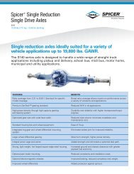
Spicer ®<br />
Single Drive Axles<br />
<strong>Service</strong> <strong>Manual</strong><br />
Spicer<br />
AXSM-0043<br />
September 2007<br />
® Single Drive Axles
The description and specifications contained in this service Any reference to brand name in this publication is made as an<br />
publication are current at the time of printing. example of the types of tools and materials recommended for use<br />
and should not be considered an endorsement. Equivalents may<br />
<strong>Corporation</strong> reserves the right to discontinue or modify its be used.<br />
models and/or procedures and to change specifications at any time<br />
without notice.<br />
I<br />
This symbol is used throughout this<br />
manual to call attention to procedures<br />
where carelessness or failure to follow<br />
specific instructions may result in personal<br />
injury and/or component damage,<br />
Departure from the instructions, choice of<br />
tools, materials and recommended parts<br />
mentioned in this publication may jeopardize<br />
the personal safety of the service<br />
technician or vehicle operator,<br />
IMPORTANT NOTICE<br />
Always use genuine replacement parts.<br />
WARNINGS: FAILURE TO FOLLOW<br />
INDICATED PROCEDURES CREATES A HIGH<br />
RISK OF PERSONAL INJURY TO THE<br />
SERVICING TECHNICIAN,<br />
Caution: Failure to follow indicated<br />
procedures may cause component damage<br />
or malfunction.<br />
Note: Additional service information not<br />
covered in the service procedures.<br />
Tip: Helpful removal and installation<br />
procedures to aid in the service of this unit.<br />
1
Axle <strong>Service</strong> and Maintenance Instructions<br />
Single Reduction Axles<br />
2<br />
Introduction<br />
<strong>Dana</strong> <strong>Corporation</strong> presents this publication to aid in maintenance and overhaul of Spicer single<br />
reduction, single drive axles.<br />
The axle models contained in this manual are of common design. Physical variances occur in the axle housing, differential<br />
gearing and axle shafts because of varying load carrying capacities (see chart on page 4). For other variables refer to the<br />
exploded view on page 5.<br />
Instructions contained herein are applicable to all axle models, unless specified otherwise.<br />
For brake information and axle mounting or suspension systems, refer to pertinent truck manufacturerÕs literature.<br />
Axle models covered in this publication:<br />
13101<br />
15101,15131<br />
16121,16131<br />
17101,17103,17121,17123,17131,17133<br />
18101.18121.18123<br />
19101,19121<br />
20101,20121<br />
21121,21131,21133<br />
22121,22123,22131,22133<br />
23121,23123,23133<br />
26121<br />
30127<br />
Contents<br />
Notice<br />
Introduction<br />
Axle and Carrier Identification<br />
Axle Housing Identification<br />
Description and Operation<br />
Differential Carrier Assembly<br />
Lubrication<br />
Changing Lube<br />
Wheel End Lubrication<br />
Cleaning, Inspection, Replacement<br />
Adjustments<br />
Wheel Bearing Adjustment<br />
Differential Carrier Adjustment<br />
Final Pinion Bearing reload Test<br />
Adjust Pinion Bearing Preload for Axles with<br />
"Slip-fit" Outer Pinion Bearings<br />
Differential Bearing Preload and Ring Gear<br />
Remove Differential Carrier Assembly<br />
Disassemble Differential Carrier<br />
Disassemble Drive Pinion<br />
Disassemble Wheel Differential<br />
Assemble Wheel Differential<br />
Differential Carrier Overhaul<br />
Assemble Drive Pinion<br />
Install Drive Pinion<br />
Install Differential and Ring Gear Assembly<br />
Adjust Differential Bearing Preload<br />
Price $3.50
Axle and Carrier Assembly Model Identification<br />
Dierential carrier identication is either stamped on the carrier itself or<br />
on a metal tag axed to the carrier, Location on the carrier is the same.<br />
Metal Tag on<br />
Differential Carrier<br />
Axle Specification Number<br />
The complete axle is identied by the specification<br />
number stamped on the rear right-hand side of the<br />
axle housing. This number identies all component<br />
parts of the axle as built by Spicer, including special<br />
OEM requirements such as yoke or ange.<br />
In addition, some axles<br />
may include a metal identication<br />
tag (see<br />
illustration).<br />
Ring Gear and Pinion Identification<br />
Ring Gear and Drive Pinion<br />
are matched parts and must be<br />
replaced in sets. Check the appropriate<br />
Spicer Axle parts book<br />
for part numbers and ordering<br />
instructions.<br />
To aid in identifying gear sets,<br />
both parts are stamped with such<br />
information as number of pinion<br />
and ring gear teeth, individual part<br />
number and matched set number<br />
(refer to adjacent drawing).<br />
.<br />
3
¨<br />
Single Reduction Axles<br />
4<br />
Description and Operation<br />
Spicer single reduction axles are<br />
of the full-floating type with a<br />
single-speed differential assembly.<br />
The gearing is spiral bevel design<br />
with drive pinion positioned at<br />
centerline of the ring gear.<br />
Drive pinion is straddle-mounted<br />
on two tapered roller bearings and<br />
a straight roller type pilot bearing.<br />
The differential assembly is mounted<br />
on two tapered roller bearings.<br />
Power flow is through the drive<br />
pinion and ring gear, and a 4 side<br />
pinion, 2 side gear type differential<br />
to the axle shafts and wheels.<br />
The majority of variances in axle<br />
models included in this manual is<br />
in ring gear size and capacities<br />
(see chart below). For detailed<br />
variances refer to exploded view<br />
of differential (page 5).
Differential Carrier Assembly<br />
Flat Washer not used on 13, 15, 16 Series.<br />
Dowel Bushing not used on 13, 15, 16, 17, 18, 21 Series<br />
Lockwire not used on 17, 18, 21, 22, 23, 26 (late 30 Series.<br />
Oil Trough & Capscrew not used on 13, 15, 16, 17, 18, 21, 22, 23, 26 (late), 30 Series.<br />
Spacer Washer not used on 13, 15, 16, 17, 18, 21, 22 Series.<br />
Dowel Pin not used on 17, 18, 19, 20, 21, 22, 23,26, 30 Series.<br />
Flat Washer not used on 15130, 16130, 17130, 19121, 20121,23,26,30 Series.<br />
2-Speed Differential Carrier is used on 22 Series. Axles so 17“ gearing will fit.<br />
Yoke Spacer used only if retrofitting 17 Series Axles with current gear / pinion sets built<br />
with 55200C Inner Pinion Bearings. Reference Instruction Sheet 129277.<br />
I<br />
5
Single Reduction Single Drive Axles<br />
6<br />
Lubrication<br />
The ability of a drive axle to deliver quiet, trouble-free operation<br />
over a period of years is largely dependent upon the use of good<br />
quality gear lubricant incorrect quantity. The most satisfactory<br />
results can be obtained by following the directions contained in this<br />
manual.<br />
The following lubrication instructions represent the most current<br />
recommendations from the Axle & Brake Division of<br />
<strong>Corporation</strong>.<br />
Approved Lubricants<br />
General-Gear lubrications acceptable under military specification<br />
(MILSPEC) MIL-L-2105D (Lubricating Oils, Gear, Multipurpose)<br />
preapproved for use in Drive Axles. The MIL-L-2105D<br />
specification defines performance and viscosity requirements for<br />
multigrade oils. It supersedes both MIL-L-2105B, MIL-L-2105C<br />
and cold weather specification Ml L-L-l 0324A. This specification<br />
applies to both petroleum-based and synthetic based gear lubricants<br />
if they appear on the most current “Qualified Products List”<br />
(QPL-2105) for MIL-L-2105D.<br />
Note: The use of separate oil additives and/or friction modifiers<br />
are not approved in Drive Axles.<br />
Synthetic based-Synthetic-based gear lubricants exhibit superior<br />
thermal and oxidation stability, and generally degrade at a lower<br />
rate when compared to petroleum-based lubricants. The performance<br />
characteristics of these lubricants include extended change<br />
intervals, improved fuel economy, better extreme temperature<br />
operation, reduced wear and cleaner component appearance. The<br />
family of gear lubricants represents a premium<br />
quality synthetic lube which fully meets or exceeds the requirements<br />
of MIL-L-2105D. These products, available in both 75W-90<br />
and 80W-140, have demonstrated superior performance in<br />
comparison to others qualified under the MINPEC, as demonstrated<br />
by extensive laboratory and field testing. For a complete list<br />
of approved synthetic lubricants contact your local<br />
representative. See back cover of this manual for appropriate<br />
phone number.<br />
Makeup Lube-Maximum amount of non-synthetic makeup lube<br />
is 100/..<br />
Viscosity/Ambient Temperature Recommendations-The following<br />
chart lists the various SAE Grades covered by MIL-L-2105D and<br />
the associated ambient temperature range from each. Those SAE<br />
grades shown with an asterisk (*) are available in the<br />
family of synthetic gear lubricants,<br />
The lowest ambient temperatures covered by this chart are -40 o<br />
F<br />
and -40 o<br />
C. Lubrication recommendations for those applications<br />
which consistently operate below this temperature range, must be<br />
obtained through the <strong>Corporation</strong> by contacting your local<br />
representative.<br />
I Grade Ambient Temperature Range<br />
75W -40 o<br />
F to -15°F (-40 o<br />
C to -26 o<br />
C)<br />
75W-80 -40 o<br />
F to 80 o<br />
F (-40 o<br />
C to 27 o<br />
C)<br />
75W-90* -40 o<br />
F to 100 o<br />
F (-40 o<br />
C to 38 o<br />
C)<br />
75W-140 -40°F and above (-40 o<br />
C and above)<br />
80W-90 -15 o<br />
F to 100 o<br />
F (-26°C to 38 o<br />
C)<br />
80W-140* -15°F and above (-26°C and above)<br />
85W-140 1O°F and above (-12°C and above)
Lube Change Intervals<br />
This product combines the latest manufacturing and part washing<br />
technology. When filled with an approved synthetic<br />
lubricant at the factory, the initial drain is not required.<br />
Change the lubricant within the first 5,000 miles of operation<br />
when not using a approved synthetic lubricant in<br />
either a new axle or after a carrier head replacement. Base<br />
subsequent lubricant changes on a combination of the following<br />
chart and user assessment of the application and operating<br />
environment.<br />
Single Reduction Single Drive Axles<br />
Severe <strong>Service</strong> Lubrication Change Intervals-Severe service<br />
applications are those where the vehicle consistently operates<br />
at or near its maximum GCW or GVW ratings, dusty or wet<br />
environments, or consistent operation on grades greater than 8%.<br />
For these applications, the ON/OFF HIGHWAY portion of the chart<br />
should be used. Typical applications are construction, logging,<br />
mining and refuse removal.<br />
Note: Remove metallic particles from the magnetic filler plug and<br />
drain plugs. Clean or replace the breather at each lubricant change.<br />
Guidelines - Lube Change Intervals for Drive Axles<br />
Lubricant Type Maximum Change Maximum Change On/Off Highway Severe Maximum Change<br />
Interval Interval <strong>Service</strong> Miles Interval<br />
Petroleum 100,000 Yearly 40,000 Yearly<br />
Based<br />
- Approved 250,000 3 Years 100,000 Yearly<br />
Synthetic<br />
7
8<br />
Checking Lube Level<br />
Remove the filler hole plug located<br />
in the axle housing cover. Lube<br />
should be level with the bottom of<br />
this hole.<br />
IMPORTANT: Lube level close<br />
enough to the hole to be seen or<br />
touched is not sufficient, It must<br />
be level with the hole.<br />
NOTE: When checking lube level,<br />
also check and clean housing<br />
breathers.<br />
Changing Lube<br />
Draining<br />
Drain when the lube is at normal operating temperature. It will run freely<br />
and minimize the time necessary to fully drain the axle.<br />
Unscrew the magnetic drain plug on the underside of the axle housing<br />
bowl section and allow the lube to drain into a suitable container. Inspect<br />
drain plug for large quantities of metal particles. After initial oil change,<br />
these are signs of damage or extreme wear in the axle, and inspection of<br />
the entire unit may be warranted. Clean the drain plug and replace it after<br />
the lube has drained completely.<br />
Filling<br />
Remove the filler hole plug from<br />
the center of the axle housing<br />
cover and fill the axle with<br />
approved lubricant until level<br />
with the bottom of the hole.<br />
NOTE: Lube fill capacities in the<br />
adjacent chart are good guidelines<br />
but will vary somewhat on the<br />
basis of the angle the axle is<br />
installed in a particular chassis.<br />
Always use the filler hole as the<br />
final reference. If lube is level with<br />
the bottom of the hole, the axle is<br />
properly filled.<br />
Axles installed at angles exceeding<br />
6¡ or operated regularly in areas<br />
requiring negotiation of grades<br />
exceeding 12% may require standpipes<br />
to allow proper fill levels.<br />
For specific recommendations,<br />
contact your local representative.<br />
See back cover of this<br />
manual for phone numbers.<br />
I<br />
Ñ<br />
Lube Capacities*<br />
DO NOT OVERFILL AXLES<br />
Housing Vendor Housing<br />
(Rectangular Arm) (Round Arm)<br />
Axle Series Pints (liters) Pints (liters)<br />
13,15 . . . . . . . . . . . . 23 (11) 19 ( 9)<br />
16 . . . . . . . . . . . . . . .<br />
17,18 . . . . . . . . . . . .<br />
33 (16)<br />
37 (18)<br />
24 (11)<br />
29 (14)<br />
19,20 . . . . . . . . . . . .<br />
38 (18)<br />
21,22 . . . . . . . . . . . . 37 (18)<br />
23,26,30 . . . . . . . . 41 (19) 34 (16)<br />
*Capacities listed are approximate. The amount of lubricant will vary with angle of<br />
axle as installed in vehicle chassis. Figures do not apply to housings not designed<br />
or manufactured by .
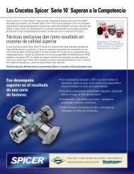
Wheel End Lubrication<br />
Single Reduction Single Drive Axles<br />
Wheel ends with an oil fill hole<br />
Following any servicing of wheel ends, the wheel hub cavities and<br />
1. Rotate the wheel end hub until the oil fill hole is up.<br />
bearings must be lubricated to prevent failure. 2. Remove the oil fill plug.<br />
Caution: Make sure the wheel ends are well lubricated<br />
with the same axle lubricant used in the axle sump, Do<br />
not pack the bearings with grease before installation as<br />
grease will prevent the proper circulation of axle<br />
lubricant and may cause wheel seal failure.<br />
3.<br />
4.<br />
Pour 1 pint of axle sump lubricant into each hub through the<br />
wheel end fill hole.<br />
Install oil fill plug and tighten to specified torque.<br />
axles may be equipped with either of two wheel end designs:<br />
Wheel ends with an oil fill hole<br />
Wheel ends without an oil fill hole<br />
See Figure 1 for cutaway views of the two different designs.<br />
Figure 1 Cutaway Views of Typical Wheel End Assemblies<br />
9
Single Reduction Single Drive Axles<br />
Wheel ends without an oil fill hole 6. With axle on a level surface, add additional lubricant through<br />
1. With axle level and wheel ends assembled, add lubricant<br />
through filler hole in axle housing cover until fluid is level with<br />
the bottom of filler hole.<br />
housing cover oil filler hole to raise lube to required level.<br />
2. Raise the left side of the axle 6 inches or more, Hold axle in<br />
this position for one minute.<br />
Note: Axles without wheel end fill holes will require approximately<br />
2.5 additional pints of lubricant to bring the lube level even with the<br />
bottom of the fill hole.<br />
3, Lower the left side.<br />
4. Raise the right side of the axle 6 inches or more. Hold axle in<br />
this position for one minute.<br />
Tip: The use of ramps or making a full lock figure eight turning<br />
maneuver at low speed will guarantee the wheel end is charged<br />
with lube. Refill axle to proper lube level, (Follow procedure on<br />
5. Lower the right side. page 8).<br />
10
Cleaning, Inspection, Replacement<br />
As the drive axle is disassembled, set all parts aside for thorough<br />
cleaning and inspection. Careful inspection will help determine whether<br />
parts should be reused. In many cases, the causes of premature wear or<br />
drive axle failure will also be revealed.<br />
Cleaning<br />
The differential carrier assembly may be steam-cleaned while mounted in<br />
the housing as long as all openings are tightly plugged. Once removed<br />
from its housing, do not steam clean differential carrier or any<br />
components. Steam cleaning at this time could allow water to be trapped<br />
in cored passages, leading to rust, lubricant contamination, and<br />
premature component wear. The only proper way to clean the assembly<br />
is to disassemble it completely. Other methods will not be effective<br />
except as preparatory steps in the process. Wash steel parts with ground<br />
or polished surfaces in solvent. There are many suitable commercial<br />
solvents available. Kerosene and diesel fuel are acceptable.<br />
WARNING: GASOLINE IS NOT AN ACCEPTABLE SOLVENT BECAUSE<br />
OF ITS EXTREME COMBUSTIBILITY. IT IS UNSAFE IN THE<br />
WORKSHOP ENVIRONMENT.<br />
Wash castings or other rough parts in solvent or clean in hot solution<br />
tanks using mild alkali solutions. If a hot solution tank is used, make<br />
sure parts are heated thoroughly, before rinsing.<br />
Rinse thoroughly to remove all traces of the cleaning solution. Dry parts<br />
immediately with clean rags.<br />
Lightly oil parts if they are to be reused immediately. Otherwise, coat<br />
with oil and wrap in corrosion-resistant paper. Store parts in a clean, dry<br />
place.<br />
Inspection<br />
Inspect steel parts for notches, visible steps or grooves created by wear.<br />
Look for pitting or cracking along gear contact lines. Scuffing,<br />
deformation or discoloration are signs of excessive heat in the axle,<br />
usually related to low lubricant levels or improper lubrication practices.<br />
Before reusing a gear set, inspect teeth for signs of excessive wear.<br />
Check tooth contact pattern for evidence of incorrect adjustment (see<br />
Adjustment Section for correct pattern).<br />
Inspect machined surfaces of cast or malleable parts. They must be free<br />
of cracks, scoring, and wear. Look for elongation of drilled holes, wear<br />
on surfaces machined for bearing fits and nicks or burrs in mating<br />
surfaces.<br />
Inspect fasteners for rounded heads, bends, cracks or damaged threads.<br />
The axle housing should be examined for cracks or leaks. Also look for<br />
loose studs or cross-threaded holes.<br />
Inspect machined surfaces for nicks and burrs.<br />
11
Adjustments<br />
12<br />
Wheel Bearing Adjustment<br />
Wheel bearings should be adjusted at regular intervals<br />
using the following procedure:<br />
PREPARATION: Provide means to capture lubricant that<br />
will escape when axle shafts are removed. Remove axle<br />
shafts. Jack the wheel to be adjusted clear of the<br />
ground.<br />
After securely blocking the vehicle to prevent rolling,<br />
release the parking brake, allowing the wheel to rotate<br />
freely.<br />
1. Remove outer adjusting nut and doweled (or tanged)<br />
washer.<br />
2. Visually inspect spindle for damage or wear. Inspect<br />
the nut and spindle threads for damage. Make certain<br />
that the nut turns without binding by cleaning the threads<br />
and applying a light coat of oil prior to adjusting the<br />
wheel bearings. Inspect tanged washer (if used).<br />
Replace washer if tangs are broken or badly misshaped.<br />
3. Torque inner nut to 200 Ibs.-ft. (272 N•m) while<br />
rotating the wheel. Loosen the nut one full turn. Retorque<br />
to 50 Ibs.-ft. (68 N•m). Back off nut exactly 1/4 of<br />
a turn.<br />
4. Install doweled (or tanged) washer. If the dowel pin<br />
and washer (or washer tang and nut flat) are not aligned,<br />
remove washer, turn it over and reinstall. For further<br />
alignment, loosen the inner nut slightly.<br />
5. Install outer nut and torque as follows:<br />
● Dowel type washer lock -300 Ibs. -ft. (408 N•m)<br />
● Tang type washer lock -250 Ibs. -ft. (229 N•m)<br />
This adjustment procedure should allow wheel to turn<br />
freely with 0.001’’-0.005” (0.025mm to 0.250 mm) endplay.<br />
NOTE: The end-play should be measured using a dial<br />
indicator with a 0.001” resolution. With the tires and<br />
wheels on the hub, rock the wheel end back and fourth<br />
before making the end-play measurement. This will<br />
result in a more accurate reading.<br />
IMPORTANT Never tighten the inner nut for alignment.<br />
This will preload the bearing and cause premature<br />
failure.<br />
WARNING: Never work under a<br />
vehicle supported only by a jack.<br />
Insure that the vehicle will not roll<br />
before releasing brakes.<br />
6. If using the tanged washer type lock, secure adjusting<br />
nuts by bending one wheel nut washer tang over each nut.<br />
Bend tang over the closest flat perpendicular to the tang<br />
(see Illustration).<br />
7. Install axle shaft gasket& axle shaft. Refill axle to<br />
proper lube level. (Follow procedure on page 8).
Adjustments<br />
Differential/ Carrier Adjustments<br />
Adjustments help provide optimum axle life and performance by correctly<br />
positioning bearings and gears under load.<br />
single drive axles require two types of adjustments: Bearings must be<br />
preloaded and ring gear tooth contact must be set.<br />
Bearing Preload — Both pinion and differential bearings Adjust Pinion Bearing Preload — Most axles<br />
require preloading. The adjustment procedures seat will be found with a “slip-fit” outer pinion bearing,<br />
these bearings in their cups for good support and free but recent design changes provide a “press-fit” on<br />
rotation under load. The pinion pilot bearing does not this bearing (in some axle models). Procedures for<br />
require a preload adjustment. adjusting both types of pinion bearing design are<br />
contained in this section.<br />
Adjust Pinion Bearing Preload for Axles With<br />
"Press-fit” Outer Pinion Bearings<br />
Trial Build-up<br />
1. Assemble the pinion bearing<br />
cage, bearings and spacer (without<br />
drive pinion or oil seal).<br />
NOTE: During assembly procedure,<br />
center bearing spacer<br />
(and spacer washer when used)<br />
between the two bearing cones.<br />
2. With the bearings well lubricated,<br />
place the assembly in the<br />
press. Position a sleeve or spacer<br />
so that load is applied directly to<br />
the back face of the outer bearing<br />
cone.<br />
Assemble these Parts for Trial Build-up.<br />
Axle Series<br />
16<br />
17/1 8/21<br />
22<br />
19/20/23/26/30<br />
3. Apply press load to the<br />
assembly and check rolling<br />
torque. Wrap soft wire around the<br />
bearing cage, attach spring scale<br />
and pull. Preload is correct when<br />
torque required to rotate the<br />
pinion bearing cage is from 10-<br />
20 inch pounds. This specification<br />
is translated into spring scale<br />
readings in the chart below.<br />
4. If necessary, Adjust Pinion<br />
Bearing Preload by changing the<br />
pinion bearing spacer. A thicker<br />
spacer will decrease preload. A<br />
thinner spacer will increase<br />
preload.<br />
Specifications for Pinion Bearing<br />
Trial Build-up Preload Test<br />
(“Press-fit” Outer Pinion Bearings)<br />
Nominal Bearing<br />
Spacer Thickness<br />
in.<br />
mm.<br />
0 . 5 2 8 13.41<br />
0.638<br />
0.638<br />
0.638<br />
0.185<br />
16.21<br />
16.21<br />
16.21<br />
4.70<br />
Cage in Press<br />
to Check Bearing<br />
Preload.<br />
Press Loads<br />
Tons Metric Tons<br />
12-13 11-12<br />
1 1 - 1 2 10-11<br />
14-15 13-14<br />
14-15 13-14<br />
19-20 17-18<br />
IMPORTANT: Once correct bearing<br />
preload has been established,<br />
note the spacer size used. Select a<br />
spacer 0.001” larger for use in the<br />
final pinion bearing cage assembly.<br />
The larger spacer compensates<br />
for slight “growth” in the bearings<br />
which occurs when they are<br />
pressed on the pinion shank. The<br />
trial build-up will result in proper<br />
pinion bearing preload in three<br />
of four cases.<br />
IMPORTANT: Do not assume that<br />
all assemblies will retain proper<br />
preload once bearings are pressed<br />
on pinion shank. FINAL PRELOAD<br />
TEST MUST BE MADE IN EVERY<br />
CASE.<br />
Spring Scale Reading<br />
(without pinion seal)<br />
(for 10-20 m-lbs. torque)<br />
(1.1-2.3 N•m)<br />
lb.s kgs.<br />
5-9 2.3-4.1<br />
5-9 2.3-4.1<br />
4-8 1.8-3.6<br />
4-7 1.8-3.2<br />
3-7 1.4-3.2<br />
13
14<br />
Final Pinion Bearing Preload Test<br />
1. Assemble the complete pinion bearing cage unit as recommended<br />
in the assembly section of this manual (Page 25).<br />
2. Apply clamp load to the pinion bearing cage assembly. Either install<br />
the yoke and torque the pinion nut to specifications or use a press to<br />
simulate nut torque (see chart below).<br />
Vise Method - If the yoke and nut are used, mount the assembly in a<br />
vise, clamping yoke firmly.<br />
Press Method - If a press is used, position a sleeve or spacer so that<br />
load is applied directly to the back-face of the outer bearing cone.<br />
3. Measure Pinion Bearing Preload - Use a spring scale to test the<br />
assembly rolling torque. To use the spring scale, wrap soft wire around<br />
the bearing cage, attach the scale and pull. Preload is correct when<br />
torque required to rotate the pinion bearing cage is from 15 to 35 inch<br />
pounds. This specification is translated into spring scale readings in the<br />
chart below.<br />
4. Adjust Pinion Bearing Preload - If necessary, adjust pinion bearing<br />
preload. Disassemble the pinion bearing cage as recommended in this<br />
manual and change the pinion bearing spacer. A thicker spacer will<br />
decrease preload. A thinner spacer will increase preload.<br />
IMPORTANT: Use the correctly sized spacer. Do not use shim stock or<br />
grind spacers. These practices can lead to loss of bearing preload and<br />
gear or bearing failure.<br />
Measuring Bearing Preload with<br />
Pinion in Vise.<br />
Measuring Bearing Preload with<br />
Pinion in Press.<br />
Specifications for Final Pinion Spring Scale Reading<br />
Bearing Preload Test (without pinion seal)<br />
("Press-fit" Outer Pinion Bearings) (for 15-35 in-lbs. torque)<br />
(1.7-4 N.m)<br />
Nut Torque Press Loads<br />
Axle Series Ft-lbs. N.m Tons Metric Tons Ib.s<br />
13/15/16 360-440 488-596 12-13 11-12 7-16<br />
17/18+ 480-600 650-813 14-15 13-14 6-14<br />
17/18/19/20/21/22Ê 560-700 759-949 14-15 13-14 6-13<br />
19/20/23/26/30ˆ 840-1020 1139-1383 19-20 17-18 5-12<br />
+1 1/4-12 Pinion Nut Ê1 1/2-18 Pinion Nut ˆ1 3/4-12 Pinion Nut, *15130 & 16130 Models only use metric nut<br />
M30 X 1.5, 17130 models use metric nut M36 X 1.5,23130 models use metric nut M \42 X 1.5<br />
kgs.<br />
3.2-7.3<br />
2.7-6.4<br />
2.7-5.9<br />
2.3-5.4
Adjustments<br />
Adjust Pinion Bearing Preload for Axles with<br />
"Slip-fit" Outer Pinion Bearings<br />
1. Lubricate bearings and assemble the drive pinion, bearings, and<br />
pinion bearing cage as recommended in the assembly section of this<br />
manual (Page 25). Use the pinion bearing spacer removed from the axle<br />
during disassembly. If the original spacer cannot be used, install the<br />
nominal spacer recommended in the adjacent chart.<br />
NOTE: Bearing spacer washer is not used on 13, 15, 16, 17, 18, 21, 22<br />
Series axles.<br />
2. Apply clamp load to the pinion bearings. Install the yoke and torque the<br />
nut to specification or use a press to simulate nut torque by applying<br />
pressure to the assembly (see chart below).<br />
Vise Method - If the yoke and nut are used, mount the assembly in a vise,<br />
clamping yoke firmly.<br />
Press Method - If a press is used, position a sleeve or spacer so that<br />
load is applied directly to the back-face of outer pinion bearing.<br />
3. Measure Pinion Bearing Preload - Use a spring scale to test the<br />
assembly rolling torque. To use the spring scale, wrap a soft wire around<br />
the bearing cage, attach the scale and pull. Preload is correct when<br />
torque required to rotate the pinion bearing cage is from 15 to 35 inch<br />
pounds. This specification is translated into spring scale readings in the<br />
chart below.<br />
4. Adjust Pinion Bearing Preload - If necessary, adjust pinion bearing<br />
preload. Disassemble the pinion bearing cage as recommended in this<br />
manual and change the pinion bearing spacer. A thicker spacer will<br />
decrease preload. A thinner spacer will increase preload.<br />
IMPORTANT: Use the correctly sized spacer. Do not use shim stock or<br />
grind spacers. These practices can lead to loss of bearing preload and<br />
gear or bearing failure.<br />
Measuring Bearing Preload with Measuring Bearing Preload with<br />
Pinion in Vise. Pinion in Press.<br />
Specifications for Pinion<br />
Bearing Preload Test<br />
("Slip-fit" Ou ter<br />
Pinion Bearings)<br />
Nut Torque Press Loads<br />
Axle Series Ft-lbs. N.m T o n s Metric Tons<br />
13/15/16* 360-440 488-596 12-13 11-12<br />
17*/18+<br />
480-600 650-813 14-15 13-14<br />
17*/18/19/20/21/22Ê 560-700 759-949 14-15 13-14<br />
19/20/23*/26/30ˆ 840-1020 1139-1383 19-20 17-18<br />
+1 1/4-12 Pinion Nut Ê1 1/2-18 Pinion Nut ˆ1 3/4-12 Pinion Nut, *15130 & 16130 Models only use metric nut<br />
M30 X 1.5, 17130 models use metric nut M36 X 1,5,23130 models use metric nut M42 X 1.5<br />
Nominal Pinion<br />
Bearing Spacers<br />
Spacer Thickness<br />
Axle Model in. mm<br />
13/15 . . . . . . . . . . . . . . . 0.528 13 .41<br />
16 . . . . . . . . . . . . . . . . . 0.638 16 .21<br />
17/18/21/22 . . . . . . . . 0.638 16.21<br />
19/20/23/26/30 . . . . . . . . 0.185 4.70<br />
Spring Scale Reading<br />
(without pinion seal)<br />
(for 15-35 m-lbs. torque)<br />
(1.7-4 N.m)<br />
Ib.s<br />
7-16<br />
6-14<br />
6-13<br />
5-12<br />
k S.<br />
3.2-7.3<br />
2.7-6.4<br />
2.7-5.9<br />
2.3-5.4<br />
15
16<br />
Differential Bearing Preload and Ring Gear<br />
Backlash Adjustment<br />
Correct differential bearing preload insures proper location of these<br />
bearings under load and helps position the ring gear for proper gear<br />
tooth contact.<br />
(Follow procedures in numerical sequence.)<br />
Adjust Diff. Bearing Preload<br />
1. Lubricate differential bearings. 3. Loosen the bearing adjuster<br />
IMPORTANT: When installing<br />
on the same side as the ring gear<br />
bearing caps and adjuster, exert<br />
teeth until its first thread is<br />
care not to cross threads.<br />
visible.<br />
/<br />
2. Install adjusters and bearing<br />
caps. Tighten bearing cap screws<br />
finger-tight. If this is difficult,<br />
use a hand wrench.<br />
4. Tighten the bearing adjuster<br />
on the back-face side of the ring<br />
gear until there is no backlash.<br />
This can be tested by facing the<br />
ring gear teeth and pushing the<br />
gear away from the body while<br />
gently rocking the gear from side<br />
to side. There should be no free<br />
movement.<br />
Rotate the ring gear and check<br />
for any point where the gear may<br />
bind. If such a point exists,<br />
loosen and retighten the back<br />
side adjuster. Make all further<br />
adjustments from the point of<br />
tightest mesh.<br />
Adjust Ring Gear Backlash<br />
To add backlash: Loosen the<br />
adjuster on the teeth side of the ring<br />
gear several notches. Loosen the<br />
opposite adjuster one notch.<br />
Return to adjuster on teeth side of<br />
the ring gear and tighten adjuster<br />
until it contacts the bearing cup.<br />
Continue tightening the same adjuster<br />
2 or 3 notches. Recheck<br />
backlash.<br />
5. At teeth side of ring gear,<br />
tighten adjuster until it contacts<br />
the bearing cup. Continue tightening<br />
adjuster two or three notches<br />
and this will preload bearings and<br />
provide backlash.<br />
6. Measure backlash with a dial indicator.<br />
USED GEARING — Reset to backlash recorded before disassembly.<br />
NEW GEARING — Backlash should be between 0.006” and 0.016”<br />
on most models. Axles with 17” or 18” ring gears require<br />
0.008” to 0.018” backlash.<br />
To remove backlash: Loosen the<br />
adjuster on the teeth side of the ring<br />
gear several notches. Tighten the<br />
opposite adjuster one notch.<br />
Return to adjuster on teeth side of<br />
ring gear and tighten adjuster until it<br />
contacts the bearing cup. Continue<br />
tightening the same adjuster 2 or 3<br />
notches. Recheck backlash.<br />
Moving adjuster one notch is the<br />
movement of the lead edge of one<br />
adjuster lug to the lead edge of the<br />
next lug past a preselected point.
Adjustments<br />
Ring Gear and Pinion Tooth Contact<br />
Check Tooth Contact Pattern (NEW GEAR)<br />
Paint twelve ring gear teeth with marking compound<br />
and roll the gear to obtain a contact pattern. The correct<br />
pattern is well-centered on the ring gear tooth with<br />
lengthwise contact clear of the toe. The length of the<br />
pattern in an unloaded condition is approximately onehalf<br />
to two-thirds of the ring gear tooth in most models<br />
and ratios.<br />
RING GEAR TOOTH NOMENCLATURE<br />
Check Tooth Contact Pattern (USED GEAR)<br />
Used gearing will not usually display the square,<br />
even contact pattern found in new gear sets. The<br />
gear will normally have a “pocket” at the toe-end<br />
of the gear tooth which tails into a contact line<br />
along the root of tooth. The more use a gear has<br />
had, the more the line becomes the dominant<br />
characteristic of the pattern.<br />
Adjust used gear sets to display the same contact<br />
pattern observed before disassembly. A correct<br />
pattern is clear of the toe and centers evenly along<br />
the face width between the top land and root.<br />
Otherwise, the length and shape of the pattern are<br />
highly variable and is considered acceptable as<br />
long as it does not run off the tooth at any point.<br />
CORRECT PATTERN (NEW GEARING)<br />
• pattern should be clear of tooth toe.<br />
CORRECT PATTERN (USED GEARING)<br />
17
18<br />
Adjust Tooth Contact Pattern<br />
If necessary, adjust the contact pattern by moving the ring gear and<br />
drive pinion. Ring gear position controls the backlash. This adjustment<br />
moves the contact pattern along the face width of the gear tooth. Pinion<br />
position is determined by the size of the pinion bearing cage shim pack. It<br />
controls contact on the tooth depth of the gear tooth.<br />
These adjustments are interrelated. As a result, they must be considered<br />
together even though the pattern is altered by two distinct<br />
operations. When making adjustments, first adjust the pinion, then the<br />
backlash. Continue this sequence until the pattern is satisfactory.<br />
Adjust Pinion Position<br />
If the gear pattern shows incorrect tooth depth contact, change drive<br />
pinion position by altering the shim pack. Used gears should achieve<br />
proper contact with the same shims removed from the axle at disassembly.<br />
INCORRECT PATTERN<br />
● Pattern too close to tooth top land and off center.<br />
If the pattern is too close to the top land of the<br />
gear tooth, remove pinion shims.<br />
INCORRECT PATTERN<br />
Pattern too close or off tooth root.<br />
If the pattern is too close to the root of the gear<br />
tooth, add pinion shims.<br />
NOTE: Check ring gear backlash after each shim change and adjust if necessary to maintain the<br />
.006¡ to .016¡ specifications. Axles with 17¡ or 18¡ ring gears require .008¡ to .018¡ backlash.<br />
Adjust Backlash<br />
If the gear pattern shows incorrect face width contact, change backlash.<br />
INCORRECT PATTERN<br />
● Pattern too close to edge of tooth toe.<br />
INCORRECT PATTERN<br />
● Pattern too far along tooth toward tooth heel.<br />
With the pattern concentrated at the toe (too far<br />
down the tooth), add backlash by loosening the<br />
bearing adjuster on the teeth side of ring gear several<br />
notches. Loosen the opposite adjuster one notch.<br />
If the pattern is concentrated at the heel (too<br />
far up the tooth), remove backlash by Ioosening the<br />
bearing adjuster on the teeth side of ring gear sev-<br />
eral notches. Tighten the opposite adjuster one notch.<br />
Return to adjuster on teeth side of ring gear and<br />
tighten adjuster until it contacts the bearing cup.<br />
Continue tightening the same adjuster 2 or 3<br />
notches. Recheck backlash.<br />
Return to adjuster on teeth side of ring gear and<br />
tighten adjuster until it contacts the bearing cup.<br />
Continue tightening the same adjuster 2 or 3<br />
notches. Recheck backlash.
Fastener Tightening Specifications<br />
Axle Series: 13, 15, 16, 17, 18, 19, 20, 21, 22, 23, 26, 30<br />
Specifications are for all axle models unless specified otherwise.<br />
●<br />
●<br />
●<br />
●<br />
Correct tightening torque values are extremely important to assure<br />
long Axle life and dependable performance. Under-tightening<br />
of attaching parts is just as harmful as over-tightening.<br />
Exact compliance with recommended torque values will assure the<br />
best resuIts.<br />
The data includes fastener size, grade and torque tightening values.<br />
Axle models are included to pinpoint identification of fasteners for<br />
your particular axle.<br />
TO determine bolt or cap screw grade, check for designation stamped<br />
on bolt head (see illustration).<br />
Bolt head markings<br />
for grade identification<br />
Grade 5 Grade 8<br />
19
Differential Carrier Replacement<br />
20<br />
Remove Differential Carrier Assembly from Axle Housing<br />
Install Differential Carrier Assembly<br />
IMPORTANT: Before installing<br />
carrier assembly, inspect and<br />
thoroughly clean interior of<br />
axle housing.<br />
NOTE: Use silicone rubber gasket<br />
compound on axle housing mating<br />
surface as shown in the illustration.<br />
Gasket compound will set in 20 minutes.<br />
Install carrier before compound<br />
sets or reapply.<br />
Axle Housing Gasket<br />
Compound Pattern.<br />
1. Install differential carrier<br />
assembly in axle housing. Install<br />
stud nuts, cap screws and lockwashers.<br />
Tighten to correct torque<br />
(see chart).<br />
2. Install axle shafts and stud nuts.<br />
(If used, also install lockwashers<br />
and taper dowels. )<br />
3. Connect driveline.<br />
Torque Chart<br />
Differential Carrier CAP SCREW<br />
Axle Series Size Grade Ft.-lbs. Nm<br />
13,15 . . . . ..7/16-14 (5) 48-56 65-75<br />
16, . . . . . . . . 1/2-13 (5) 75-85 101-115<br />
17,18,19,<br />
20,21,22,<br />
23,26,30 5/8-11 (5) 160-176 217-239<br />
5/8-18 (8) 200-230 271-312<br />
NUT<br />
17,1819,20,<br />
21,22,23,<br />
26,30 5/8-18 220-240 298-325<br />
4. Fill axle with correct lube (see<br />
Lubrication Section).<br />
IMPORTANT: When axle has been<br />
disassembled or housing, gears,<br />
axle shafts or wheel equipment<br />
replaced, check axle assembly for<br />
proper differential action before<br />
operating vehicle. Wheels must<br />
rotate freely and independently.
Differential Carrier Overhaul<br />
Disassemble Differential Carrier<br />
NOTE: If gear set is to be reused, check tooth contact pattern and ring<br />
gear backlash before disassembling differential carrier. Best results are<br />
obtained when established wear patterns are maintained in used<br />
gearing. Omit this step if the gear set is to be replaced.<br />
1. Mount Differential Carrier<br />
Assembly in repair stand. Loosen<br />
but do not remove pinion nut.<br />
4. Using a chain hoist, lift ring<br />
gear and differential assembly out<br />
of carrier.<br />
2. Punch mark differential bearing<br />
caps. If reusing gear set, also<br />
punch mark bearing adjusters for<br />
reference during assembly.<br />
5. Remove pinion bearing cage<br />
cap screws, then drive pinion,<br />
cage and yoke assembly out of<br />
carrier.<br />
IMPORTANT: Do not allow pinion<br />
to drop on hard surface. Remove<br />
shim pack.<br />
IMPORTANT: If gear set is to<br />
be reused, keep pinion bearing<br />
cage shim pack intact for use in<br />
reassembly. If the original shims<br />
cannot be reused, record the<br />
number and size of shims in the<br />
pack.<br />
3. Cut lockwire. Remove cap<br />
screws, flat washers and bearing<br />
caps.<br />
21
22<br />
Disassemble Drive Pinion<br />
NOTE: drive<br />
axles may be equipped<br />
with either "slip-fit" or<br />
"press-fit" outer pinion<br />
bearings. Procedures<br />
are contained in this<br />
section for disassembly<br />
of both types.<br />
NOTE: Lubricate parts<br />
with gear lube during<br />
reassembly.<br />
IMPORTANT: During the following<br />
yoke removal procedure, the<br />
drive pinion may fall out of bearings<br />
and cage. Do not allow pinion<br />
to drop on hard surface.<br />
1. Remove yoke. If pinion nut was<br />
not loosened during earlier disassembly,<br />
clamp assembly in vise<br />
jaws, use brass pads to prevent<br />
damage. Loosen and remove<br />
pinion nut. Remove yoke from<br />
pinion.<br />
4. Remove and retain bearing<br />
spacer from pinion (for 19, 20, 23,<br />
26, 30 Series Axles, remove and<br />
retain bearing spacer washer).<br />
2. For pinion with "press-fit" bearing<br />
cone, support cage and press<br />
pinion out of bearing cage and<br />
bearing cone.<br />
For pinion with "slip-fit" bearing<br />
cone, the cage, outer bearing and<br />
pinion can usually be disassembled<br />
easily without a press. If<br />
difficulty is experienced, use<br />
a press.<br />
3. Remove oil seal and bearing<br />
cone from cage. Discard oil seal.<br />
Remove bearing cups with suitable<br />
puller.<br />
5. Remove pilot bearing and inner bearing cone from pinion, using<br />
a split-type puller. Use two procedure steps to remove each bearing<br />
(see photos above).<br />
First, mount puller vertically to split<br />
bearing.<br />
Second, mount puller horizontally<br />
to remove bearing.
Differential Carrier Overhaul<br />
Disassemble Wheel Differential<br />
3. Lift out side gear and thrust<br />
washer.<br />
6. Remove bearing cones from<br />
case haIves using suitable puller<br />
(see photos).<br />
7. Remove bearing cone from<br />
plain case half in two steps: First,<br />
mount puller vertically to split<br />
bearing (see photo). This action<br />
will start moving bearing off case.<br />
Second, mount puller vertically to<br />
remove cone.<br />
8. Remove bearing cone from<br />
flanged case half using suitable<br />
puller.<br />
IMPORTANT: During following<br />
procedure, place differential<br />
assembly on malleable surface<br />
to prevent damage when ring gear<br />
falls off its mounting position.<br />
1. Remove nuts and bolts fastening<br />
ring gear to differential cases,<br />
allowing gear to fall free. If gear<br />
does not fall, tap outer diameter<br />
with soft mallet to loosen.<br />
2. Punch mark differential cases<br />
for correct location during assembly.<br />
Remove cap screws and lift off<br />
plain differential case half.<br />
4. Lift out spider, side pinions and<br />
thrust washers.<br />
Puller Mounted Vertically<br />
to Split Bearing.<br />
5. Remove side gear and thrust<br />
washer.<br />
Removing Bearing Cone<br />
from Flanged Case Half.<br />
23
24<br />
Assemble Wheel Differential<br />
NOTE: Lubricate differential parts with gear lube during assembly.<br />
1. Press bearing cone on flanged<br />
differential case.<br />
4. Assemble side pinion and<br />
thrust washers on spider. Place<br />
this assembly in flanged differential<br />
case. Rotate gears and check<br />
for proper mesh.<br />
7. Install ring gear. Secure with<br />
bolts and nuts and tighten to<br />
correct torque (see chart).<br />
2. Press bearing cone on plain<br />
differential case.<br />
5. Place side gear and thrust<br />
washer on side pinions.<br />
NOTE: Fasteners using self-<br />
Iocking nylon "patches" may be<br />
reused if not damaged, but should<br />
be secured by a few drops of<br />
Loctite #277 on threaded surface<br />
of differential case during following<br />
assembly procedures.<br />
3. Place thrust washer and side<br />
gear in flanged differential case.<br />
6. Align punch marks and install<br />
plain case half. Install cap screws<br />
and tighten to correct torque (see<br />
chart).<br />
Lockwire cap screws on 13, 15 and<br />
16, 19, 20 Series axles.<br />
Check differential for free rotation<br />
by turning side gear hub. Differential<br />
may require up to 50 ft-lbs.<br />
(68 N´m) torque to rotate.<br />
Torque Chart<br />
Ring Gear BOLT/NUT<br />
Axle Series Size Grade Ft.-lbs. N.m<br />
13,15 . . . . . . . . . 7/16-20 (9) 60-70 81-94<br />
16 . . . . . . . . . . . .<br />
17,18,19,20,21,<br />
1 /2-20 (8) 90-100 122-135<br />
22,23,26,30 . . . . 5/8-1 8 (8) 180-220 244-298<br />
Differential Case CAP SCREW<br />
13,15 . . . . . . . . . 7/16-14 (5) 45-55 61-74<br />
16 . . . . . . . . . . . . 1/2-13 (8) 95-115 128-155<br />
17,18,21,22 . . . . 9/16-12 (8) 116-130 157-176<br />
19,20,<br />
23,26,30 . . . . . . 5/8-1 1 (8) 165-195 223-264
Differential Carrier Overhaul<br />
Assemble Drive Pinion ("Press-fit" outer pinion bearing).<br />
NOTE: drive axles may be NOTE: Lubricate parts<br />
equipped with either "slip-fit" or with gear lube during<br />
"press-fit" outer pinion bearings. reassembly.<br />
Procedures are contained in this<br />
section for assembly of both types.<br />
Press Bearing<br />
Cups in Cage.<br />
ïBearing Spacer Washer only<br />
used on 19, 20, 23, 26, 30 Series<br />
"A" - Cups must be firmly seated in cage<br />
Check with feeler gauge (0.001")<br />
after Installation<br />
NOTE: Install cups one at a time<br />
1. Press bearing cups in cage.<br />
IMPORTANT: At this point, select<br />
pinion bearing spacer by using the<br />
"trial build-up" procedure described<br />
in the Adjustments Section of this<br />
manual (Page 13).<br />
4. Press inner bearing cone on<br />
pinion. IMPORTANT: To prevent<br />
bearing damage, use suitable<br />
sleeve that only contacts inner<br />
race of bearing cone. ,<br />
2. Press pilot bearing in pinion.<br />
IMPORTANT: To prevent bearing<br />
damage, use suitable sleeve that<br />
only contacts inner bearing race.<br />
5. Install bearing spacer selected<br />
during "trial build-up" (and spacer<br />
washer for 19, 20, 23, 26, 30 Series<br />
Axles) on pinion.<br />
3. Stake pilot bearing using staking<br />
tool.<br />
NOTE: During pinion bearing<br />
installation, locate each part in<br />
same position that was used in<br />
"Trial-Buildup" Preload Test.<br />
6. Install bearing cage on drive<br />
pinion.<br />
25
Assemble Drive Pinion ("Press-fit" outer pinion bearing) (Cont"d)<br />
TO PRESS ON SEAL OUTER FLANGE 1<br />
7. Press outer bearing cone on 8. With pinion installed and bearing<br />
pinion. preload adjustment complete, in-<br />
IMPORTANT: To prevent bearing stall oil seal with a press. Use propdamage,<br />
use suitable sleeve that erly sized sleeve to fit seal to preonly<br />
contacts inner race of bearing vent distortion during installation.<br />
cone. At this stage of assembly,<br />
"final-check" pinion bearing<br />
preload. See Adjustment Section<br />
of this manual.<br />
Assemble Drive Pinion ("Slip-fit" outer pinion bearing<br />
26<br />
Press Bearing<br />
Cups in Cage.<br />
I PRESS<br />
1<br />
ñAÍ „ Cups must be firmly seated in cage.<br />
Check with feeler gauge (0.001î)<br />
after Installation<br />
NOTE: Install cups one at a time.<br />
1. Press bearing cups in cage.<br />
NOTE: Prior to installation of<br />
flange (or yoke), lubricate oil seal<br />
lip and make sure flange (or yoke)<br />
is clean and dry.<br />
9. Install flange, flat washer and<br />
nut (flat washer is used only on<br />
13, 15, 16, 17, 18, 20, 21, 22 Series<br />
axles). Tighten nut to correct<br />
torque (see chart).<br />
NOTE: 15130, 16130, 17130 series axles<br />
do not use flat washers.<br />
2. Press pilot bearing in pinion. 3. Stake pilot bearing using staking<br />
IMPORTANT: To prevent bearing tool. This is essential to retain the<br />
damage, use suitable sleeve that bearing.<br />
only contacts inner bearing race.
Differential Carrier Overhaul<br />
Assemble Drive Pinion ("Slip-fit" outer pinion bearing) (con't)<br />
4. Press inner bearing cone on<br />
pinion.<br />
IMPORTANT: To prevent bearing<br />
damage, use suitable sleeve that<br />
only contacts inner race of bearing<br />
cone.<br />
7. Install pinion outer bearing<br />
cone. Do not install oil seal until<br />
bearing adjustment is complete.<br />
NOTE: At this stage in assembly,<br />
check pinion bearing preload<br />
described in Adjustment Section<br />
of this manual for "slip-fit" outer<br />
pinion bearing (Page 15).<br />
5. Select existing or nominal bearing<br />
spacer and install on pinion.<br />
On 19, 20, 23, 26, 30 Series axles,<br />
also install spacer washer.<br />
8. With pinion installed and bearing<br />
preload adjustment complete, install<br />
oil seal with a press. Use properlysized<br />
sleeve to fit seal to prevent<br />
distortion during installation.<br />
6. Install bearing cage on drive<br />
pinion.<br />
NOTE: Prior to installation of<br />
flange (or yoke), lubricate oil seal<br />
lip and make sure flange (or yoke)<br />
is clean and dry.<br />
9. Install flange, flat washer and<br />
nut (flat washer is used only on<br />
13, 15, 16, 17, 18, 20, 21, 22 Series<br />
axles). Tighten nut to correct<br />
torque (see chart).<br />
NOTE: 15130.16130.17130 series axles<br />
do not use flat washers.<br />
Torque Chart<br />
„<br />
27
Install Drive Pinion<br />
1. Place shim pack on carrier<br />
making sure lube hole is clear.<br />
,<br />
28<br />
Torque Chart<br />
Bearing Cage CAP SCREW<br />
Axle Series Size Grade Ft.-lbs. N¥m<br />
13,15,16<br />
17,18,21,22 . . . 9/16-12 (5) 110-125 149-170<br />
19,20,<br />
23,26,30 . . . . . 5/8-11 (5) 160-176 217-239<br />
NOTE: If gear set is to be reused,<br />
install same quantity and size<br />
of shims removed during disassembly.<br />
When installing a new<br />
gear set, use nominal shim pack<br />
indicated below.<br />
2. Install pinion assembly. Install<br />
bearing cage cap screws and<br />
lockwashers.<br />
Torque cap screws (see chart).<br />
Install Differential and Ring Gear Assembly<br />
(13, 75, 16, 17, 18, 19, 20, 21, 23, 26, 30 Series)<br />
NOTE: Lubricate bearings during the following assembly procedures.<br />
1. Place ring gear and differential<br />
assembly in carrier. Carefully lower<br />
the assembly until bearing cones<br />
rest on carrier.<br />
2. Install bearing cups at both<br />
sides of differential case. Install<br />
bearing adjusters and caps.<br />
Nominal Shim Pack<br />
Axle Series in. mm<br />
13/15/16 . . . . . . 0.022 0.558<br />
17/18/21/22 . . . 0.023 0.584<br />
19/20 . . . . . . . . . 0.024 0.609<br />
23/26/30 . . . . . . 0.024 0.609<br />
3. Install and tighten bearing cap<br />
screws finger-tight. If this is difficult,<br />
use hand wrench.<br />
NOTE: The assembly is now<br />
ready for adjustment of differential<br />
bearing preload, ring gear backlash<br />
and gear tooth contact (see<br />
page 30).
Differential Carrier Overhaul<br />
Install Differential and<br />
NOTE: Lubricate bearings during<br />
the following assembly<br />
procedures.<br />
1. Place ring gear and differential<br />
assembly in carrier. Carefully<br />
lower the assembly until bearing<br />
cones rest on carrier.<br />
4. At back-face side of gear,<br />
install bearing cap and cap screws.<br />
Tighten cap screws finger-tight. If<br />
this is difficult, use hand wrench.<br />
NOTE: If removed, install bearing<br />
cup in adjuster, using a press.<br />
Place bar stock through opening<br />
in differential. Place bearing<br />
adjuster and cup assembly on<br />
bar stock (see photo).<br />
Raise and lower differential<br />
assembly while threading adjuster<br />
into proper position.<br />
NOTE: Make sure adjuster threads<br />
are well-lubricated.<br />
Ring Gear Assembly (22 Series Axles)<br />
2. At teeth-side of ring gear,<br />
install bearing cup, bearing<br />
adjuster and bearing cap.<br />
3. Install and tighten bearing cap<br />
screws finger-tight. If this is difficult,<br />
use hand wrench.<br />
NOTE: Tighten bearing adjuster<br />
until its first thread is visible.<br />
NOTE: With bearing adjusters and caps assembled to carrier, the carrier<br />
assembly is now ready for adjustment of bearing preload, ring gear<br />
backlash and gear tooth contact (see page 30).<br />
29
Adjust Differential Bearing Preload:<br />
30<br />
1. At the teeth-side of ring gear, position bearing adjuster until its first<br />
thread is visible.<br />
2. At the back-face side of ring gear, tighten adjuster until there is no<br />
backlash.<br />
3. At the teeth-side of ring gear, tighten adjuster until it contacts the<br />
bearing cup. Continue tightening adjuster two or three notches. This<br />
will preload bearings and provide backlash.<br />
4. Check Ring Gear Backlash. Measure backlash with a dial indicator.<br />
Specifications are listed below. Refer to page 21 for detailed instructions<br />
on adjusting backlash.<br />
Ring Gear Backlash Specifications<br />
USED GEARING „ Reset to backlash recorded before disassembly.<br />
NEW GEARING „ Note: Check ring gear backlash after each shim change<br />
and adjust if necessary to maintain the .006" to .016"<br />
specifications. Axles with 17" or 18" ring gears require<br />
.008" to .018" backlash.<br />
5. Check Ring Gear Tooth Contact. Paint ring gear teeth and check tooth<br />
contact pattern. Correct tooth patterns are illustrated below. For checking<br />
and adjusting procedures, see page 21.<br />
6. With ring gear and pinion adjusted correctly, align adjusters and<br />
locks, then tighten differential bearing cap screws to correct torque<br />
(see chart).<br />
All Axles, except 22 Series: Install adjuster locks and cotter pins.<br />
Lockwire differential bearing cap screws.<br />
22 Series Axles Only: On teeth-side of ring gear, install lock and<br />
cotter pin. On back-face side of ring gear, install "T" shaped lock<br />
and cap screws. Torque screws to 160-176 ft-lbs. (217-239 N.m).<br />
Lockwire all cap screws (both sides of ring gears).<br />
CORRECT PATTERN (USED GEARING)<br />
Torque Chart<br />
Bearing Cap CAP SCREW<br />
Axle Series Size Grade Ft.-lbs. N´m<br />
13,15 . . . . . . . . 5/8-1 1 (8) 170-190 230-258<br />
16...........11/16-11 (8) 240-280 325-379<br />
17,18,21 . . . . . 3/4-10 (8) 360-440 488-596<br />
19,20,22,<br />
23,26,30 . . . . . 13/16-10 (8) 370-430 501-583<br />
Adjusting Bearing Adjuster.<br />
Checking Ring Gear Backlash.<br />
CORRECT PATTERN (NEW GEARING)
<strong>Dana</strong> Aftermarket Group<br />
PO Box 321<br />
Toledo, Ohio 43697-0321<br />
Warehouse Distributors: 1.800.621.8084<br />
OE Dealers: 1.877.777.5360<br />
www.spicerparts.com<br />
AXSM-0043 Printed in U.S.A.<br />
Copyright <strong>Dana</strong> Limited, 2012.<br />
All rights reserved. <strong>Dana</strong> Limited.