TW190 Turbo 2764.pdf - Arbtalk
TW190 Turbo 2764.pdf - Arbtalk
TW190 Turbo 2764.pdf - Arbtalk

Create successful ePaper yourself
Turn your PDF publications into a flip-book with our unique Google optimized e-Paper software.
CONTENTS<br />
Section Page No.<br />
INTRODUCTION 1<br />
PURPOSE OF MACHINE 2<br />
MACHINE DIMENSIONS & SPECIFICATIONS 2<br />
PARTS LOCATION DIAGRAMS 3 & 4<br />
SAFE WORKING 6<br />
Operator’s Personal Protective Equipment Required 6<br />
Basic Woodchipping Safety 6<br />
General Safety Matters - Do’s and Dont’s 7<br />
Noise Test 8<br />
OPERATING INSTRUCTIONS 9<br />
Safe Transportation 9<br />
Hitching onto the Tow Ball 9<br />
Unhitching the Chipper 9<br />
Delivery 10<br />
Operator’s Personal Protective Equipment Required 10<br />
Manual Controls 10<br />
Auto Controls 11<br />
Emergency Stopping 11<br />
Daily Checks Before Starting 11<br />
Engine Controls 11<br />
Starting the Engine 11<br />
Controlling the Engine Speed 11<br />
Stopping the Engine 12<br />
Before Using the Chipper 12<br />
Starting to Chip 12<br />
Discharge Controls 12<br />
Chipping 13<br />
Blockages 13<br />
Hydraulic Oil Lever Indicator 13<br />
Fuel Level Indicator 13<br />
SERVICE INSTRUCTIONS 14<br />
Service Schedule 15<br />
Safe Maintenance 16<br />
Safe Lifting of the Chipper 16<br />
Spares 16<br />
Battery Removal and Maintenance 16<br />
Change Hydraulic Oil and Filter 16<br />
Copper Safety Information 17<br />
Battery Safety Information 17<br />
Change Blades 19<br />
Check Fittings 20<br />
Check Hoses 20<br />
Tension Drive Belts 20<br />
Grease the Roller Box Slides 21<br />
Grease the Roller Spline and Bearing 21<br />
Grease Jack Stand 21<br />
Grease the Discharge Flange 21<br />
Greasing Rotor Bearings 21<br />
Engine Manufacturer’s Handbook 21<br />
WARRANTY STATEMENT 22<br />
EC DECLARATION OF CONFORMITY CERTIFICATE 23<br />
IDENTIFICATION PLATES 24<br />
DECALS 25 & 26<br />
ELECTRICAL DETAIL 27<br />
HYDRAULIC LAYOUT 28<br />
CIRCUIT DIAGRAM 29<br />
PARTS LISTS 30 - 46<br />
30th Aug 11
TIMBERWOLF 190TDHB (<strong>Turbo</strong>) 1<br />
Thank you for choosing this Timberwolf brushwood chipper. Timberwolf chippers are<br />
designed to give safe and dependable service if operated according to the instructions.<br />
Before using your new chipper, please take time to<br />
read this manual which contains<br />
IMPORTANT HEALTH AND SAFETY INFORMATION<br />
and explains the chipper controls. Failure to do so could result in:<br />
- personal injury<br />
- equipment damage<br />
- damage to property<br />
- a member of the general public becoming injured<br />
This manual covers the operation and maintenance of the Timberwolf TW 190TDHB<br />
(<strong>Turbo</strong>). All information in this manual is based on the latest product information<br />
available at the time.<br />
All the information you need to operate the machine safely and effectively is contained<br />
within pages 2 to 13. Ensure that all operators are properly trained for operating this<br />
machine, especially with regard to safe working practices.<br />
Timberwolf's policy of constantly improving their products may involve major or minor<br />
changes to the chippers or their accessories. Timberwolf reserves the right to make<br />
changes at any time without notice and without incurring any obligation.<br />
Due to improvements in design and performance during production there may be, in<br />
some cases, minor discrepancies between the actual chipper and the text in this<br />
manual.<br />
The manual should be considered a permanent part of the<br />
machine and should remain with it if the machine is resold.<br />
!<br />
INTRODUCTION<br />
Always follow safe operating and maintenance practices<br />
CAUTION or WARNING<br />
Be aware of this symbol and where shown,<br />
carefully follow the instructions.<br />
This caution symbol indicates important safety messages in this manual. When<br />
you see this symbol, be alert to the possibility of injury to yourself or others, and<br />
carefully read the message that follows.
The Timberwolf TW 190TDHB (<strong>Turbo</strong>) brushwood chipper is designed to chip solid wood material up<br />
to 190 mm in diameter. It is capable of chipping up to 6.5 tonnes of brushwood per hour.<br />
2310 mm<br />
1300 mm<br />
TIMBERWOLF 190TDHB (<strong>Turbo</strong>) 2<br />
Engine type Kubota 4-cylinder turbo diesel<br />
Maximum power 33kW (45hp)<br />
Cooling method Water cooled<br />
Overall weight 1018kg<br />
Starting method Electric<br />
Roller feed Twin series hydraulic motors<br />
PURPOSE OF MACHINE<br />
DIMENSIONS<br />
TIMBERWOLF<br />
45/190 TURBO VORTEX<br />
1510 mm<br />
3990 mm with standard tow head (3385 mm with feed tray folded)<br />
Serial No. Location<br />
The serial number can be<br />
found on the identification<br />
plate located on the<br />
chassis beam.<br />
TIMBERWOLF TW 190TDHB FIXED TOWHEAD SPECIFICATION<br />
Maximum diameter material 190mm (7½")<br />
Fuel capacity 50 litres<br />
Hydraulic oil capacity 15 litres<br />
Material processing capacity up to 6.5 tonnes/hr<br />
Fuel type Diesel
2300mm<br />
TIMBERWOLF 190TDHB (<strong>Turbo</strong>) 3<br />
TIMBERWOLF 190TDHBA ADJUSTABLE TOWHEAD SPECIFICATION<br />
1640mm<br />
Engine type Kubota 4-cylinder turbo diesel<br />
Maximum power 33kW (45hp)<br />
Cooling method Water cooled<br />
Overall weight 1150kg<br />
Starting method Electric<br />
Roller feed Twin series hydraulic motors<br />
TIMBERWOLF<br />
45/190 TURBO VORTEX<br />
1510mm<br />
4900mm with adjustable tow head (4280mm with feed tray folded)<br />
ADJUSTING THE TOWHEAD HEIGHT<br />
Serial No. Location<br />
The serial number can be<br />
found on the identification<br />
plate located on the<br />
chassis beam.<br />
Maximum diameter material 190mm (7½")<br />
Fuel capacity 50 litres<br />
Hydraulic oil capacity 15 litres<br />
Material processing capacity up to 6.5 tonnes/hr<br />
Fuel type Diesel<br />
The TW 190TDHBA chipper has the ability to adjust the towhead height to correspond with the<br />
vehicles towing point.<br />
The preferred towing angle of any chipper is with the<br />
1<br />
chassis level to the ground. The adjustable head has<br />
the ability to move between 300mm from the ground<br />
to 875mm giving an overall adjustment of 575mm.<br />
The towhead latch and handbrake fundamentally<br />
work the same as a fixed standard towhead,<br />
however the front section of the head is retained in<br />
position via a locking ring and single clamp handle.<br />
To adjust the height the locking handle located on<br />
the side of the head (1) is turned in an anticlockwise<br />
direction to allow for the locking ring to disengage<br />
from its apposing ring. An internal damper is fitter to<br />
support the heads weight allowing both hands free<br />
to adjust the height. Once the desired height has<br />
been achieved the locking handle is turned<br />
clockwise until tight. The latching of the hitch is as normal as is the fitting of the light plug and<br />
breakaway cable as outlined in the ‘Hitching onto the tow ball’ section on page 9.
FEED FUNNEL<br />
SAFETY BAR<br />
FUEL TANK<br />
TOOL BOX<br />
HYDRAULIC<br />
OIL TANK<br />
HYDRAULIC<br />
OIL FILTER<br />
PARTS LOCATOR 4<br />
ROLLER<br />
CONTROLS<br />
DISCHARGE<br />
TUBE<br />
TIMBERWOLF<br />
45/190 TURBO VORTEX<br />
ROTOR<br />
HOUSING<br />
DISCHARGE<br />
BUCKET<br />
DISCHARGE<br />
ADJUSTMENT<br />
CONTROL<br />
LIFTING EYE<br />
THROTTLE<br />
AIR INTAKE<br />
ENGINE<br />
GUARDS<br />
TOW HEAD
ROTOR<br />
PULLEY<br />
DRIVE<br />
PULLEY<br />
ROTOR<br />
PARTS LOCATOR 5<br />
AIR INTAKE<br />
HYDRAULIC<br />
PUMP<br />
IN-LINE<br />
FUEL FILTER<br />
TOP<br />
ROLLER SLIDE<br />
ENGINE<br />
CONTROL PANEL<br />
FUEL<br />
PUMP<br />
BATTERY<br />
FUEL FILTER<br />
DIP<br />
STICK<br />
OIL FILTER<br />
AIR FILTER<br />
ALTERNATOR<br />
EXHAUST<br />
RESERVE TANK<br />
DIRECTIONAL<br />
CONTROL<br />
VALVE<br />
RADIATOR<br />
JOCKEY<br />
WHEEL<br />
ASSEMBLY<br />
STARTER<br />
MOTOR
!<br />
SAFE WORKING 6<br />
WARNING<br />
The chipper will feed material through on its own. To do this, it relies on<br />
sharp blades on the chipper rotor. To keep the blades sharp, only feed the<br />
machine with clean brushwood. DO NOT put muddy/dirty wood, roots,<br />
potted plants, bricks, stones or metal into the chipper.<br />
OPERATOR'S PERSONAL PROTECTIVE EQUIPMENT REQUIRED<br />
Chainsaw safety helmet<br />
fitted with mesh visor and<br />
recommended ear defenders<br />
to the appropriate<br />
specifications.<br />
Work gloves with<br />
elasticated wrist.<br />
Steel toe cap safety boots.<br />
BASIC WOODCHIPPING SAFETY<br />
The operator should be aware of the following points:<br />
MAINTAIN A SAFETY EXCLUSION ZONE around the chipper of at least 10 metres for the<br />
general public or employees without adequate protection. Use hazard tape to identify this<br />
working area and keep it clear from debris build up. Chips should be ejected away from any<br />
area the general public have access to.<br />
HAZARDOUS MATERIAL - Some species of trees and bushes are poisonous. The chipping<br />
action can produce vapour, spray and dust that can irritate the skin. This may lead to<br />
respiratory problems or even cause serious poisoning. Check the material to be chipped before<br />
you start. Avoid confined spaces and use a facemask if necessary.<br />
BE AWARE when the chipper is processing material that is an awkward shape. The material<br />
can move from side to side in the funnel with great force. If the material extends beyond the<br />
funnel, the brash may push you to one side causing danger. Badly twisted brash should be<br />
trimmed before being chipped to avoid thrashing in the feed funnel.<br />
BE AWARE that the chipper can eject chips out of the feed funnel with considerable force.<br />
Always wear full head and face protection.<br />
ALWAYS work on the side of the machine furthest from any local danger, e.g. not road side.<br />
!<br />
Close fitting heavy-duty<br />
non-snag clothing.<br />
Face mask if<br />
appropriate.<br />
DO NOT<br />
wear rings, bracelets,<br />
watches, jewellery or any<br />
other items that could be<br />
caught in the material and<br />
draw you into the chipper.
ALWAYS stop the chipper engine before making<br />
any adjustments, refuelling or cleaning.<br />
ALWAYS check rotor has stopped rotating and<br />
remove chipper ignition key before maintenance<br />
of any kind, or whenever the machine is to be left<br />
unattended.<br />
ALWAYS check the machine is well supported<br />
and cannot move.<br />
ALWAYS operate the chipper with the engine set<br />
to maximum speed when chipping.<br />
ALWAYS check (visually) for fluid leaks.<br />
ALWAYS take regular breaks. Wearing personal<br />
protective equipment for long periods can be<br />
tiring and hot.<br />
ALWAYS keep hands, feet and clothing out of<br />
feed opening, discharge and moving parts.<br />
ALWAYS use the next piece of material or a push<br />
stick to push in short pieces. Under no<br />
circumstances should you reach into the funnel.<br />
<br />
ALWAYS keep the operating area clear of people,<br />
animals and children.<br />
ALWAYS keep the operating area clear from<br />
debris build up.<br />
ALWAYS keep clear of the chip discharge tube.<br />
Foreign objects may be ejected with great force.<br />
ALWAYS ensure protective guarding is in place<br />
before commencing work. Failure to do so may<br />
result in personal injury or loss of life.<br />
ALWAYS operate the chipper in a well ventilated<br />
area - exhaust fumes are dangerous.<br />
SAFE WORKING 7<br />
GENERAL SAFETY MATTERS<br />
DO’S AND DON’TS<br />
DO NOT operate chipper unless available light is<br />
sufficient to see clearly.<br />
DO NOT use or attempt to start the chipper<br />
without the feed funnel, guards and discharge<br />
unit securely in place.<br />
DO NOT stand directly in front of the feed funnel<br />
when using the chipper. Stand to one side.<br />
DO NOT allow -<br />
BRICKS STRING CLOTH PLASTIC STONES<br />
METAL GLASS RUBBER ROOTS BEDDING<br />
PLANTS<br />
- to enter the machine, as damage is likely.<br />
DO NOT smoke when refuelling.<br />
DO NOT let anyone who has not received<br />
instruction operate the machine.<br />
DO NOT climb on the machine at any time.<br />
DO NOT handle material that is partially engaged<br />
in the machine.<br />
DO NOT touch any exposed wiring while<br />
machine is running.<br />
DO NOT use the chipper inside buildings.<br />
!
MACHINE:<br />
NOTES:<br />
SAFE WORKING 8<br />
TW 190TDHB (<strong>Turbo</strong>)<br />
NOISE TEST<br />
Tested Chipping 120 mm x 120 mm Corsican Pine 1.5m in<br />
length<br />
Noise levels above 80dB (A) will be experienced at the working position. Wear ear protection<br />
at all times to prevent possible damage to hearing. All persons within a 4 metre radius must<br />
also wear good quality ear protection.<br />
89.4dB Calculated<br />
96.6 dB<br />
R= 4 metres<br />
R= 10 metres<br />
95.6 dB<br />
99.9 dB<br />
98.9 dB<br />
Guaranteed Sound Power: 119dB (A)<br />
95.2 dB<br />
95.1 dB<br />
As required by Supply of Machinery (safety) regulations of 2008.<br />
89.4dB Calculated<br />
89.4dB Calculated
OPERATING INSTRUCTIONS 9<br />
SAFE TRANSPORTATION<br />
WARNING<br />
! DO NOT RIDE ON THE CHIPPER WHEN IT IS BEING TOWED. !<br />
WHEN towing a chipper do not exceed the maximum permitted towing speed for the country<br />
concerned.<br />
ON rough or bumpy road surfaces reduce speed accordingly to protect your machine from<br />
unnecessary vibration.<br />
WHEN towing off road be aware of objects that may catch the chipper undergear.<br />
WHEN towing off road ensure inclination is not excessive.<br />
AVOID excessively pot holed ground.<br />
WHEN reversing the chipper the short wheel base will react quickly to steering input.<br />
ALWAYS check the discharge tube is tight before moving.<br />
KEEP tyre pressures inflated to 2.9 bar or 42 psi.<br />
CHECK wheel nuts are tightened to 90Nm or 65 lbs ft.<br />
CLEAR loose chippings and debris from the machine before departing.<br />
ENSURE the feed funnel is closed and the catches are is properly engaged before departing.<br />
HITCHING ONTO THE TOW BALL<br />
CHECK the ball head is well greased.<br />
WIND jockey wheel assembly anticlockwise until the tow head is above the height of the ball<br />
hitch on the vehicle.<br />
REVERSE the vehicle so the ball hitch is directly below the tow head.<br />
ATTACH the breakaway cable to a strong point on the vehicle, not the ball hitch.<br />
GRASP handle on tow head and push back catch with thumb.<br />
WIND the jockey wheel assembly clockwise, to lower the tow head onto the ball hitch.<br />
RELEASE handle and continue to wind jockey wheel clockwise. The tow head should snap<br />
into place on the ball hitch. If it doesn't, repeat previous 2 steps.<br />
WIND jockey wheel up until fully retracted and the jockey wheel frame is seated in its notch on<br />
the stem. The chipper weight should be fully on the vehicle.<br />
RELEASE the jockey wheel clamp and slide the jockey wheel assembly fully up.<br />
TIGHTEN clamp on the jockey wheel assembly.<br />
CONNECT electrical plug to socket on rear of towing vehicle and check operation of all the<br />
trailer and vehicle lights.<br />
THE chipper is now properly attached to the vehicle.<br />
UNHITCHING THE CHIPPER<br />
APPLY handbrake.<br />
DISCONNECT the electrical cable from the vehicle socket.<br />
RELEASE breakaway cable.<br />
RELEASE the jockey wheel assembly clamp.<br />
LOWER the jockey wheel assembly fully.<br />
RETIGHTEN the jockey wheel assembly clamp.<br />
WIND the jockey wheel assembly anticlockwise until it starts to take the weight of the chipper.<br />
GRASP the handle and release the catch with your thumb.<br />
CONTINUE to wind the jockey wheel anticlockwise. This should lift the tow head clear of the ball hitch.<br />
DRIVE the vehicle clear of the chipper.<br />
WIND the jockey wheel assembly to a suitable point where the chipper is level.<br />
THE chipper is now fully detached from the vehicle.
OPERATING INSTRUCTIONS 10<br />
DELIVERY<br />
All Timberwolf 190TDHB (<strong>Turbo</strong>) machines have a full pre - delivery inspection before leaving the factory<br />
and are ready to use. Read and understand this instruction manual before attempting to operate the<br />
chipper. In particular, read pages 6-8 which contain important health and safety information and advice.<br />
OPERATOR’S PERSONAL PROTECTIVE EQUIPMENT REQUIRED<br />
CHAINSAW SAFETY HELMET fitted with visor<br />
and recommended ear defenders to an<br />
appropriate specification.<br />
HEAVY-DUTY work gloves with elasticated wrist.<br />
Control Panel Diagram<br />
See page 6 for more detailed information.<br />
MANUAL CONTROLS<br />
CLOSE - FITTING heavy-duty non-snag clothing.<br />
SAFETY footwear.<br />
FACE MASK (if appropriate).<br />
Roller control box - is the control box above the feed opening of the chipper funnel. Its function is to control<br />
the feed rollers. The feed rollers draw material into the machine. It does not control the main rotor.<br />
RED SAFETY BAR = This is the large red bar that surrounds the feed tray and side of the feed<br />
funnel. The bar is spring loaded and connected to a switch that will interrupt the power to the rollers.<br />
The switch is designed so that it only activates if the bar is pushed to the limit of its travel. The rollers<br />
stop instantly, but can be made to turn again by pressing either the GREEN FEED or BLUE REVERSE<br />
control buttons.<br />
RED SAFETY BAR TEST<br />
To ensure the safety bar is always operational it must be activated once before each work session.<br />
The rollers will not function until the bar is activated. This procedure must be repeated each time the<br />
ignition is switched off.<br />
WARNING<br />
DO NOT remove, jam, disable, bypass, override or otherwise<br />
impede the effectiveness of the red safety bar.<br />
! !<br />
GREEN BUTTON = Forward feed - Push the button once - this activates the rollers and will allow you<br />
to start chipping (if the rotor speed is high enough).<br />
RED BUTTON = Emergency stop - This button stops the rollers from feeding. It overrides all other<br />
buttons or bars and will not allow the other buttons to function until it has been reset. To reset, pull out until<br />
it returns to its original position. The forward and reverse buttons will now function.<br />
BLUE BUTTON = Reverse feed - allows you to back material out of the rollers. The rollers will only<br />
turn in reverse as long as you keep pressing the button. You do not have to press the STOP button<br />
before pressing the GREEN FEED button to recommence feeding.<br />
BLUE<br />
REVERSE<br />
FEED<br />
PANEL<br />
RED STOP FEED - EMERGENCY<br />
STOP BUTTON<br />
PUSH TO STOP<br />
PULL TO RESET<br />
RED SAFETY BAR<br />
GREEN<br />
FORWARD<br />
FEED<br />
PANEL<br />
Do not rely on the red bar to keep the rollers stationary if it is<br />
necessary to clear or touch the rollers. Always switch off the<br />
machine and remove ignition key before approaching the rollers.
OPERATING INSTRUCTIONS 11<br />
AUTO CONTROLS<br />
The engine management unit controls the feed rate of the material going into the chipping chamber.<br />
If the engine speed is below the predetermined level, the engine management unit will not allow the<br />
feed rollers to work in the forward “infeed” direction, until the rotor speed rises above the<br />
predetermined level. At this point, the feed rollers will start turning without warning. The reverse<br />
function will work at any engine speed.<br />
EMERGENCY STOPPING<br />
There are two ways of stopping the TW 190TDHB (<strong>Turbo</strong>) chipper in the event of an emergency.<br />
STOPPING THE ROLLERS<br />
-Activating the red safety bar will stop the rollers immediately. To restart the rollers, just push the<br />
green forward button or blue reverse button.<br />
-Pushing the red Emergency button on the roller control box will also stop the rollers immediately. The<br />
button will stay in the “pushed in” position, and will require resetting (pulling out) before being able to<br />
restart the roller functions.<br />
DAILY CHECKS BEFORE STARTING<br />
LOCATE the machine on firm level ground.<br />
CHECK machine is well supported and<br />
cannot move.<br />
CHECK jack stand is lowered and secure.<br />
CHECK all guards are fitted and secure.<br />
CHECK the discharge unit is in place and<br />
fastened securely.<br />
CHECK discharge tube is pointing in a safe<br />
direction.<br />
ENGINE CONTROLS<br />
The engine controls are in two locations. The engine ignition is on the<br />
control panel in the centre of the machine, and the throttle lever is on the<br />
bonnet (see parts locator on pg. 3).<br />
STARTING THE ENGINE<br />
ENSURE throttle lever is in the slow (tortoise)<br />
position.<br />
INSERT key. Turn to heat.<br />
HEATER LED comes on.<br />
WAIT FOR HEATER LED TO GO OUT.<br />
TURN key to engage starter motor.<br />
RELEASE key once engine starts.<br />
Do not engage starter motor for more than 20<br />
seconds - allow one minute before attempting to<br />
start. Investigate reasons for failure to start.<br />
CHECK the feed funnel to ensure no objects<br />
are inside.<br />
CHECK feed tray is in up position - to<br />
prevent people reaching rollers.<br />
CHECK controls as described below.<br />
CHECK (visually) for fluid leaks.<br />
CHECK fuel and hydraulic oil levels.<br />
For parts location see diagrams on pages 4 & 5.<br />
OFF ON HEAT START<br />
0<br />
1<br />
CONTROLLING ENGINE SPEED<br />
The engine has two throttle settings, idle and fast. These are controlled by the throttle<br />
lever on the bonnet. Moving the lever towards the ‘Hare’ on the pictogram will<br />
increase engine speed while moving it towards the ‘Tortoise’ will decrease engine<br />
speed.<br />
2<br />
POWER<br />
ON LED<br />
HEATER<br />
ON LED<br />
POWER<br />
ON /OFF<br />
& START<br />
HOURS<br />
COUNTER<br />
0<br />
1<br />
1462975<br />
2
OPERATING INSTRUCTIONS 12<br />
BEFORE USING THE CHIPPER<br />
IT IS ESSENTIAL TO CARRY OUT THE FOLLOWING TESTS to check safety equipment - this<br />
sequence of tests will only take a few seconds to carry out. We recommend that these tests are<br />
carried out daily. Observing the function as described will confirm that the safety circuits are working<br />
correctly. This is also a good opportunity to remind all operators of the control and emergency stop<br />
systems.<br />
1 2<br />
PRESS THE GREEN<br />
BUTTON<br />
THE ROLLERS<br />
SHOULD TURN FORWARDS<br />
PRESS THE RED<br />
SAFETY BAR<br />
THE ROLLERS<br />
SHOULD STOP<br />
4 5 6<br />
7<br />
PRESS THE GREEN<br />
BUTTON AGAIN<br />
THE ROLLERS SHOULD<br />
TURN FORWARDS<br />
STOPPING THE ENGINE<br />
MOVE the throttle lever to the ‘Tortoise’ to reduce the engine speed to idle.<br />
LEAVE the engine running for 1 minute.<br />
TURN the power switch to position 0. The engine should stop after a few seconds.<br />
REMOVE the ignition key.<br />
WITH THE ENGINE RUNNING AT FULL SPEED<br />
PRESS THE EMERGENCY<br />
RED BUTTON<br />
THE ROLLERS<br />
SHOULD STOP<br />
3<br />
PRESS THE BLUE BUTTON<br />
THE ROLLERS SHOULD TURN<br />
BACKWARDS ONLY WHILE THE<br />
BUTTON IS PRESSED<br />
PRESS THE BLUE<br />
BUTTON<br />
THE ROLLERS<br />
SHOULD NOT TURN<br />
PULL TO RESET<br />
THE RED BUTTON<br />
THE MACHINE IS<br />
READY TO USE<br />
STARTING TO CHIP<br />
WARNING<br />
Do not use or attempt to start the chipper without the protective<br />
! !<br />
guarding and discharge unit securely in place. Failure to do so may<br />
result in personal injury or loss of life.<br />
CHECK that chipper is running smoothly.<br />
RELEASE the catches on the feed tray and lower. Pull to release the red emergency stop button.<br />
PRESS the green control button. The rollers will commence turning.<br />
STAND to one side of the feed funnel.<br />
PROCEED to feed material into the feed funnel.<br />
DISCHARGE CONTROLS<br />
ROTATION<br />
Controlling the discharge is an essential part of safe working.<br />
BUCKET ANGLE<br />
1. Slacken nut using<br />
integral handle.<br />
1<br />
4. Adjust the bucket to the desired<br />
angle using the handle provided.<br />
2. Rotate tube.<br />
3. Retighten nut.
OPERATING INSTRUCTIONS 13<br />
CHIPPING<br />
Wood up to 190 mm diameter can be fed into the feed funnel. Put the butt end in first and engage it<br />
with the feed roller. The hydraulic feed rollers will pull the branch into the machine quite quickly. Large<br />
diameter material will have its feed rate automatically controlled by the engine management unit.<br />
Sometimes a piece of wood that is a particularly awkward shape is too strong for the feed rollers to<br />
break. This will cause the top roller to either bounce up and down on the wood or both rollers to stall.<br />
If this occurs press the BLUE REVERSE button until the material has been released. Pull the material<br />
out of the feed funnel and trim it so the chipper can handle it.<br />
Both feed rollers should always turn at the same speed. If one or both rollers stop or suddenly slow<br />
down it may be that a piece of wood has become stuck behind one of the rollers. If this occurs press<br />
the BLUE REVERSE button and hold for 2 seconds - then repress GREEN FEED button. This should<br />
enable the rollers to free the offending piece of material and continue rotation at the correct speed. If<br />
the rollers continue to stall in the 'forward feed' or 'reverse feed' position push the RED STOP<br />
BUTTON, turn engine off, remove ignition key and investigate.<br />
BLOCKAGES<br />
Always be aware that what you are putting into the chipper must come out. If the chips stop coming<br />
out of the discharge tube but the chipper is taking material in - STOP IMMEDIATELY. Continuing to<br />
feed material into a blocked machine may cause damage and will make it difficult to clear.<br />
If the chipper becomes blocked proceed as follows:<br />
STOP the engine and remove the keys.<br />
REMOVE the two rotor housing bolts.<br />
OPEN the rotor housing fully.<br />
THE material causing the blockage should fall clear.<br />
WARNING<br />
Do not reach into the rotor housing with unprotected hands. There are<br />
sharp blades and any small movement of the rotor may cause serious injury.<br />
! !<br />
EMPTY loose debris from inside the rotor housing.<br />
CHECK that the discharge tube is clear before continuing.<br />
THE rotor housing does not have to be completely clear to continue.<br />
SHUT the rotor housing and replace both bolts securely.<br />
RESTART the engine.<br />
ALLOW machine time to clear excess chips still remaining in rotor housing before you continue<br />
feeding brushwood. Feed in a small piece of wood while watching to make sure that it comes out of<br />
the discharge. If this does not clear it, repeat the process and carefully inspect the discharge tube to<br />
find any obstruction.<br />
NOTE<br />
Continuing to feed the chipper with brushwood once it has become blocked will cause the chipper to<br />
compact the chips in the rotor housing and it will be difficult and time consuming to clear.<br />
AVOID THIS SITUATION - WATCH THE DISCHARGE TUBE AT ALL TIMES.<br />
HYDRAULIC OIL LEVEL INDICATOR<br />
This can be viewed through the wall of the tank. Maximum and minimum marks are provided.<br />
FUEL LEVEL INDICATOR<br />
The fuel level can be seen through the wall of the fuel tank.
SERVICE INSTRUCTIONS 14<br />
THE FOLLOWING PAGES DETAIL ONLY<br />
BASIC MAINTENANCE GUIDELINES SPECIFIC<br />
TO YOUR CHIPPER.<br />
! !<br />
THIS IS NOT A WORKSHOP MANUAL.<br />
THE FOLLOWING GUIDELINES ARE NOT EXHAUSTIVE AND DO NOT EXTEND<br />
TO GENERALLY ACCEPTED STANDARDS OF ENGINEERING/MECHANICAL<br />
MAINTENANCE THAT SHOULD BE APPLIED TO ANY PIECE OF MECHANICAL<br />
EQUIPMENT AND THE CHASSIS TO WHICH IT IS MOUNTED.<br />
AUTHORISED TIMBERWOLF SERVICE AGENTS ARE FULLY TRAINED IN ALL<br />
ASPECTS OF TOTAL SERVICE AND MAINTENANCE OF TIMBERWOLF<br />
WOODCHIPPERS. YOU ARE STRONGLY ADVISED TO TAKE YOUR CHIPPER TO<br />
AN AUTHORISED AGENT FOR ALL BUT THE MOST ROUTINE MAINTENANCE<br />
AND CHECKS.<br />
TIMBERWOLF ACCEPTS NO RESPONSIBILITY FOR THE FAILURE OF THE<br />
OWNER/USER OF TIMBERWOLF CHIPPERS TO RECOGNISE GENERALLY<br />
ACCEPTED STANDARDS OF ENGINEERING/MECHANICAL MAINTENANCE<br />
AND APPLY THEM THROUGHOUT THE MACHINE.<br />
THE FAILURE TO APPLY GENERALLY ACCEPTED<br />
STANDARDS OF MAINTENANCE, OR THE PERFORMANCE<br />
OF INAPPROPRIATE MAINTENANCE, MAY INVALIDATE<br />
WARRANTY IN WHOLE OR IN PART.<br />
PLEASE REFER TO YOUR AUTHORISED<br />
TIMBERWOLF SERVICE AGENT FOR<br />
SERVICE AND MAINTENANCE.<br />
! !
!<br />
SERVICE INSTRUCTIONS 15<br />
WARNING<br />
Always immobilise the machine by stopping the engine, removing the ignition<br />
key and disconnecting the battery before undertaking any maintenance work. !<br />
SERVICE SCHEDULE<br />
Check water. <br />
Check radiator is clear. <br />
Check engine oil - top up if necessary (10W-30). <br />
Check for engine oil / hydraulic oil leaks. <br />
Check fuel level.<br />
Check feed funnel, feed roller cover, access covers,<br />
<br />
engine covers and discharge unit are securely fitted. <br />
Check blades. <br />
Clean air filter element.<br />
DEPENDING ON WORKING ENVIRONMENT<br />
Check tyre pressure is 2.9 Bar (42 psi). <br />
Check safety bar mechanism.<br />
Check for tightness all nuts, bolts and fastenings<br />
<br />
making sure nothing has worked loose. <br />
Grease discharge flange.<br />
Check tension of main drive belts<br />
<br />
(and tension if necessary). <br />
Grease the roller box slides. OR AS REQUIRED - SEE PAGE 21<br />
Grease the roller spline and bearing. OR AS REQUIRED - SEE PAGE 21<br />
Check fuel pipes and clamp bands. <br />
Check battery electrolyte level. <br />
Check for loose electrical wiring. <br />
Grease jack stand.<br />
Replace hydraulic oil filter - every year or 100 hours<br />
<br />
after service or repair work to the hydraulic system. OR <br />
Replace hydraulic oil. OR <br />
Replace fuel pipes and clamp bands.<br />
Check coolant.<br />
Change engine oil.<br />
Replace engine oil filter cartridge.<br />
Check valve clearance.<br />
Replace anvils.<br />
Axle maintenance.<br />
Tow head maintenance.<br />
Daily<br />
Check<br />
50<br />
Hours<br />
100<br />
Hours<br />
500<br />
Hours<br />
REFER TO YOUR ENGINE<br />
SUPPLIERS MANUAL<br />
1<br />
Year<br />
RETURN TO DEALER - 1500 HRS OR 3 YRS<br />
REFER TO SUPPLIERS<br />
INSTRUCTION SHEET<br />
NOTE: Your Timberwolf woodchipper is covered by a full 12 months parts and labour warranty.<br />
Subject to correct maintenance and proper machine usage, the bearings are guaranteed for 12<br />
months regardless of hours worked by the machine. In conditions of 'heavy usage' - i.e. in excess of<br />
500 hours per year - it is recommended that the bearings are changed annually to ensure that the<br />
machine retains optimum working performance.
SERVICE INSTRUCTIONS<br />
HANDLE blades with extreme caution to<br />
avoid injury. Gloves should always be<br />
worn when handling the cutter blades.<br />
THE drive belts should be connected<br />
while changing blades, as this will restrict<br />
sudden movement of the rotor.<br />
SAFE MAINTENANCE<br />
ALWAYS IMMOBILISE THE ENGINE BEFORE UNDERTAKING ANY MAINTENANCE WORK ON THE<br />
CHIPPER BY REMOVING THE KEY AND DISCONNECTING THE NEGATIVE LEAD AT THE BATTERY.<br />
SPARES<br />
THE major components of this machine<br />
are heavy. Lifting equipment must be<br />
used for disassembly.<br />
CLEAN machines are safer and easier to<br />
service.<br />
AVOID contact with hydraulic oil and fuel.<br />
Only fit genuine Timberwolf replacement blades, screws and chipper spares. Failure to do so<br />
will result in the invalidation of the warranty and may result in damage to the chipper, personal<br />
injury or even loss of life.<br />
BATTERY REMOVAL AND MAINTENANCE<br />
16<br />
WARNING<br />
Refer to the battery safety section on pages 17-18. !<br />
!<br />
BATTERY MAINTENANCE<br />
1. Undo the two M10 nuts on the battery cover.<br />
2. Remove the battery cover.<br />
3. The battery can be serviced in this position.<br />
SAFE LIFTING OF THE CHIPPER<br />
The lifting eye is designed to lift the machine’s weight only. Do not use<br />
hoist hook directly on the lifting eye, use a correctly rated safety shackle.<br />
Inspect the lifting eye prior to each use - DO NOT USE LIFTING EYE IF<br />
DAMAGED.<br />
BATTERY REMOVAL<br />
1. Remove the negative battery lead.<br />
2. Remove the positive battery lead.<br />
When reinstalling the battery apply a small smear of Vaseline to the terminals.<br />
CHANGE HYDRAULIC OIL AND FILTER<br />
WARNING<br />
Use plastic gloves to keep oil off skin and dispose of the used oil and filter in<br />
an ecologically sound way. The oil and filter should be changed once a year<br />
or at any time it becomes contaminated. Before starting check that the<br />
chipper is standing level and brush away loose chips.<br />
1. Remove the black screw cap from the top of the filter housing.<br />
1<br />
2. Partially remove filter element from inner cup. Leave filter to<br />
drain for 15 minutes.<br />
3. Remove filter element from cup when clear of hydraulic oil.<br />
4. Remove drain plug and drain oil into a suitable container.<br />
5. Replace drain plug.<br />
2<br />
6. Refill with VG 32 hydraulic oil until the level is between the min and<br />
max lines marked on the tank (about 40 litres).<br />
4<br />
7. Refit the filter cup, install a new filter element and refit the<br />
black screw cap, to the filter housing, ensuring o-ring remains<br />
in place.<br />
! !
Product name: Copper Ease.<br />
SERVICE INSTRUCTIONS 17<br />
Copper Ease contains no hazardous ingredients at or above regulatory disclosure limits, however,<br />
safety precautions should be taken when handling (use of oil-resistant gloves and saftey glasses are<br />
recommended - respiratory protection is not required). Avoid direct contact with the substance and<br />
store in a cool, well ventilated area avoiding sources of ignition, strong oxidising agents and strong<br />
acids. Dispose of as normal industial waste (be aware of the possible existance of regional or national<br />
regulations regarding disposal), do not discharge into drains or rivers.<br />
In case of fire: in combustion the product emits toxic fumes, extinguish with alcohol or polymer foam,<br />
carbon dioxide or dry chemical powder. Wear self-contained breathing apparatus and protective clothing<br />
to prevent contact with skin and eyes.<br />
FIRST AID<br />
COPPER EASE SAFETY INFORMATION<br />
Skin contact: there may be mild irritation at the site of contact, wash immediately with plenty of soap<br />
and water.<br />
Eye contact: there may be irritation and redness, bathe the eye with running water for 15 minutes.<br />
Ingestion: there may be irritation of the throat, do not induce vomiting, wash out mouth with water.<br />
A safety data sheet for this product can be obtained by writing to the manufacturer at the<br />
following address: Comma Oil and Chemicals Ltd., Deering Way, Gravesend, Kent DA12 2QX.<br />
Tel: 01474 564311, Fax: 01474 333000.<br />
WARNING NOTES AND SAFETY REGULATIONS FOR FILLED LEAD-ACID BATTERIES<br />
For safety reasons, wear eye protection<br />
when handling a battery.<br />
Keep children away from acid and<br />
batteries.<br />
BATTERY SAFETY INFORMATION<br />
Fires, sparks, naked flames and smoking are<br />
prohibited.<br />
-Avoid causing sparks when dealing with cables<br />
and electrical equipment, and beware of<br />
electrostatic discharges.<br />
-Avoid short circuits, otherwise:<br />
Explosion hazard:<br />
-A highly explosive oxyhydrogen gas mixture is<br />
produced when batteries are charged.<br />
Corrosive hazard:<br />
-Battery acid is highly corrosive, therefore:<br />
-Wear protective gloves and eye protection.<br />
-Do not tilt the battery, acid may escapefrom the<br />
vent openings.<br />
First aid:<br />
-Rinse off acid splashed in the eyes immediately<br />
for several minutes with clear water! Then<br />
consult a doctor immediately.<br />
-Neutralise acid splashes on the skin or clothes<br />
immediately with acid neutraliser (soda) or soap<br />
suds, and rinse with plenty of water.<br />
-If acid is swallowed, consult a doctor immediately.<br />
Warning notes: The battery case can become brittle, to<br />
avoid this:<br />
-Do not store batteries in direct sunlight.<br />
-Discharged batteries may freeze up, therefore<br />
store in an area free from frost.<br />
Disposal:<br />
-Dispose of old batteries at an authorised<br />
collection point.<br />
-The notes listed under item 1 are to be followed<br />
for transport.<br />
-Never dispose of old batteries in household<br />
waste.
SERVICE INSTRUCTIONS 18<br />
BATTERY SAFETY INFORMATION...cont.<br />
1. Storage and transport<br />
- Batteries are filled with acid.<br />
- Always store and transport batteries upright<br />
and prevent from tilting so that no acid can<br />
escape.<br />
- Store in a cool and dry place.<br />
- Do not remove the protective cap from the<br />
positive terminal.<br />
- Run a FIFO (first in-first out)warehouse<br />
management system.<br />
2. Initial operation<br />
- The batteries are filled with acid at a density of<br />
1.28g/ml during the manufacturing process and<br />
are ready for use.<br />
- Recharge in case of insufficient starting power<br />
(cf. section 4).<br />
3. Installation in the vehicle and removal from<br />
the vehicle<br />
- Switch off the engine and all electrical<br />
equipment.<br />
- When removing, disconnect the negative<br />
terminal first.<br />
- Avoid short circuits caused by tools, for example.<br />
- Remove any foreign body from the battery tray,<br />
and clamp battery tightly after installation.<br />
- Clean the terminals and clamps, and lubricate<br />
slightly with battery grease.<br />
- When installing, first connect the positive<br />
terminal, and check the terminal clamps for<br />
tight fit.<br />
- After having fitted the battery in the vehicle,<br />
remove the protective cap from the positive<br />
terminal, and place it on the terminal of the<br />
replaced battery in order to prevent short<br />
circuits and possible sparks.<br />
- Use parts from the replaced battery, such as<br />
the terminal covers, elbows, vent pipe<br />
connection and terminal holders (where<br />
applicable); use available or supplied filler caps.<br />
- Leave at least one vent open, otherwise there<br />
is a danger of explosion. This also applies<br />
when old batteries are returned.<br />
4. Charging<br />
- Remove the battery from the vehicle;<br />
disconnect the lead of the negative terminal first.<br />
- Ensure good ventilation.<br />
- Use suitable direct current chargers only.<br />
- Connect the positive terminal of the battery to<br />
the positive output of the charger. Connect the<br />
negative terminal accordingly.<br />
- Switch on the charger only after the battery has<br />
been connected, and switch off the charger first<br />
after charging has been completed.<br />
- Charging current-recommendation: 1/10<br />
ampere of the battery capacity Ah.<br />
- Use a charger with a constant charging voltage<br />
of 14.4V for re-charging.<br />
- If the acid temperature rises above 55 o Celsuis,<br />
stop charging.<br />
- The battery is fully charged when the charging<br />
voltage has stopped rising for two hours.<br />
5. Maintenance<br />
- Keep the battery clean and dry.<br />
- Use a moist anti-static cloth only to wipe the<br />
battery, otherwise there is a danger of<br />
explosion.<br />
- Do not open the battery.<br />
- Recharge in case of insufficient starting power<br />
(cf. section 4).<br />
6. Jump Starting<br />
- Use the standardised jumper cable in<br />
compliance with DIN 72553 only, and follow the<br />
operating instructions.<br />
- Use batteries of the same nominal voltage only.<br />
- Switch off the engines of both vehicles.<br />
- First connect the two positive terminals (1) and<br />
(2), then connect the<br />
negative terminal of the<br />
charged battery (3) to a<br />
metal part (4) of the<br />
vehicle requiring<br />
assistance away from the battery.<br />
- Start the engine of the vehicle providing<br />
assistance, then start the engine of the vehicle<br />
requiring assistance for a maximum of 15<br />
seconds.<br />
- Disconnect the cables in reverse sequence<br />
(4-3-2-1).<br />
7. Taking the battery out of service<br />
- Charge the battery; store in a cool place or in<br />
the vehicle with the negative terminal<br />
disconnected.<br />
- Check the battery state of charge at regular<br />
intervals, and correct by recharging when<br />
necessary (cf. section 4).<br />
12V<br />
(2)<br />
(1)<br />
(3) (4)<br />
12V
!<br />
4<br />
SERVICE INSTRUCTIONS 19<br />
CHANGING BLADES<br />
WARNING<br />
Wear heavy duty gloves for the blade changing operation.<br />
1. Turn off the chipper and remove the key.<br />
2. Remove the negative battery lead.<br />
3. Turn the discharge tube to point across the<br />
machine.<br />
4. Use a 24mm socket with extension bar to<br />
remove the two M16 nuts clamping the rotor<br />
housing shut.<br />
5. Carefully lift the rotor housing until its rests on<br />
its stop.<br />
6. Using the fan blades turn the rotor so the first<br />
blade to be changed is in a convenient<br />
position. Wedge rotor against the housing<br />
with a wooden block to prevent turning.<br />
7. Brush away all dirt and debris from the rotor<br />
and blades.<br />
8. With a 24mm spanner/socket undo the two<br />
nyloc nuts that are holding the blade in place.<br />
9. Grasp the blade by the flat edges while<br />
wearing heavy duty gloves.<br />
10. Withdraw the blade from the rotor.<br />
11. If the blades are being rotated and not<br />
replaced, do not remove the blade bolts.<br />
12. If the blades are to be renewed, place the<br />
blade on a flat surface and tap the top of<br />
the blade bolts with a hammer. The bolts<br />
are designed for this. They should loosen<br />
from the blade. Withdraw them completely.<br />
13. Clean the back surface of the blade, blade<br />
bolts and blade area of the rotor before<br />
WARNING<br />
Always sharpen blades on a regular basis. Failure to do so will cause the machine<br />
to under perform and will overload engine and bearings causing machine<br />
breakdown. Blades must not be sharpened beyond the wear mark (see diagram).<br />
! Failure to comply with this could result in machine damage, injury or loss of life.<br />
5<br />
THIS PROCEDURE SHOULD ONLY BE UNDERTAKEN WITH THE DISCHARGE IN PLACE.<br />
10<br />
reseating blades. The blades must not<br />
have any material underneath them<br />
when tightened. If they are not flat and<br />
tight they will become loose quickly.<br />
14. Reassemble the blades, bolts, washers and<br />
nuts in the order shown in the diagram<br />
above. Use only genuine Timberwolf nuts<br />
and washers, as they are of a higher grade<br />
than normally stocked at fastener factories.<br />
Failure to use the appropriate grade nuts or<br />
washers may result in damage, injury or<br />
death. The use of genuine Timberwolf<br />
blades and bolts is recommended.<br />
15. Apply a smear of anti seize compound<br />
(copper ease) to the bolt threads and back<br />
face of the nuts. Do not apply copper grease<br />
onto the counter bore faces of the blades or<br />
bolts.<br />
16. Wedge rotor against housing with a wooden<br />
block to tension nuts.<br />
17. A calibrated torque wrench must be used<br />
to tighten the bolts to a torque setting of<br />
125 lbs ft (170 Nm).<br />
18. Repeat this procedure for the other blade.<br />
19. Slowly lower the rotor housing to its original<br />
position.<br />
20. Refit the two M16 nuts and tighten to<br />
60 lbs ft (80Nm).<br />
21. Re-attach battery lead.<br />
6<br />
WEAR<br />
MARK<br />
8<br />
!<br />
!
1<br />
2<br />
SERVICE INSTRUCTIONS 20<br />
CHECK FITTINGS<br />
The TW 190TDHB (<strong>Turbo</strong>) is subject to large vibrations during the normal course of operation.<br />
Consequently there is always a possibility that nuts and bolts will work themselves loose. It is<br />
important that periodic checks are made to ensure the security of all fasteners. Uncalibrated torque<br />
wrenches can be inaccurate by as much as 25%. It is therefore essential that a calibrated<br />
torque wrench is used to achieve the tightening torques listed below.<br />
Size Pitch Head Torque Ibs.ft Torque Nm<br />
Blade Bolts M16 Fine 24 mm Hex 125 170<br />
Anvil Retaining Bolts M12 Standard 10 mm Allen Key 65 88<br />
Rotor Housing Clamp Bolts M16 Standard 24 mm Hex 60 80<br />
Hyd Motor Retaining Cap Screws M12 Standard 10 mm Allen Key 60 81<br />
Roller Box Retaining Bolts M16 Standard 24 mm Hex 105 140<br />
Rotor Main Shaft Retaining Screws M12 Standard 10 mm Allen Key 105 140<br />
Rotor Stub Shaft Retaining Screws M10 Fine 8 mm Allen Key 45 61<br />
Large Rotor Shaft Retaining Nut M39 Nut 60 mm Hex 450 610<br />
Funnel Retaining Nuts M12 Standard 19 mm Hex 60 80<br />
General M8 Standard 13 mm Hex 17 23<br />
General M10 Standard 17 mm Hex 34 46<br />
General M12 Standard 19 mm Hex 60 80<br />
Drain Bung in Fuel Tank 3/8” BSP - 22 mm Hex 25 33.8<br />
Fuel Take-off in Fuel Tank 3/4” BSP - 32 mm Hex 40 54.2<br />
CHECK HOSES<br />
All the hydraulic hoses should be regularly inspected for chafing and leaks. The hydraulic system is<br />
pressurized to 150 Bar (2175 PSI) and thus the equipment containing it must be kept in good condition.<br />
Identify the hoses that run to the top motor. These have the highest chance of damage as they are<br />
constantly moving. If any hydraulic components are changed new seals should be installed during<br />
reassembly. Fittings should then be retightened.<br />
TENSION DRIVE BELTS<br />
NOTE: There will normally be a rapid drop in tension during run-in period for new belts. When new<br />
belts are fitted, check the tension every 2 - 3 hours and adjust until the tension remains constant.<br />
Belt failures due to lack of correct tensioning will not be covered under your Timberwolf warranty.<br />
1. Remove the near side roller box guard.<br />
2. Open the rotor housing.<br />
3. Slacken the four 24 mm nuts that retain the<br />
roller box (bolt is retained underneath).<br />
4. Slacken the lock nuts on the belt tension bracket.<br />
5. Turn appropriate lock nut to move roller box in<br />
desired direction. Take care to keep roller box<br />
square. Slightly tighten nut A (see diagram)<br />
when tension is near desired amount. Continue<br />
to tension belts until correct tension is achieved.<br />
3<br />
A<br />
For instructions on checking belt tension &<br />
correct belt tension values, please refer to<br />
the Timberwolf V-Belt Tensioning Data Table<br />
(pg. 45).<br />
6. When the belt tension is correct tighten<br />
the four 24 mm roller box retaining nuts.<br />
7. Tighten the lock nuts.<br />
8. Grease the roller box slides and rollers.<br />
9. Close the rotor housing and fasten securely.<br />
10. Refit the near side roller box guard.<br />
4
SERVICE INSTRUCTIONS 21<br />
GREASE THE ROLLER BOX SLIDES<br />
NOTE: This should be done every 50 hours. In dirty or dusty conditions or during periods of<br />
hard work it should be done more frequently. If the slides become dry the top roller will tend<br />
to hang up and the pulling-in power of the rollers will<br />
be much reduced. Excessive wear will ensue.<br />
1<br />
1. Remove the near side roller box guard.<br />
2. Open the rotor housing.<br />
3. Apply multipurpose grease directly to the slide surfaces<br />
indicated. DO NOT USE GRAPHITE BASED GREASE.<br />
4. Close the rotor housing.<br />
5. Refit the near side roller box guard.<br />
GREASE THE ROLLER SPLINE AND BEARING<br />
NOTE: This should be done regularly. In dirty and dusty conditions or during periods of hard<br />
work it should be weekly. If the bearings and splines are allowed to run dry premature wear<br />
will occur resulting in a breakdown and the need for replacement parts. This failure is not<br />
warranty. Early signs of insufficient grease includes squeaking or knocking rollers.<br />
1. Open the rotor housing.<br />
2. Locate two grease nipples; one in the centre of each roller shaft.<br />
3. Use a pump action grease gun to apply a generous amount of grease to<br />
each roller drive. DO NOT USE GRAPHITE BASED GREASE.<br />
4. Close the rotor housing.<br />
5. To penetrate all the bearing surfaces thoroughly, start the machine and<br />
operate the rollers for 20 seconds. Switch off the machine. Repeat this<br />
greasing/running procedure a further 3 times.<br />
GREASE THE JACK STAND<br />
The jack stand requires intermittent greasing to maintain a smooth operation.<br />
1. Brush off dirt with a stiff brush.<br />
2. Apply grease liberally to screw thread using a brush.<br />
3. Wind mechanism up and down a couple of times to ensure grease has covered all surfaces.<br />
2<br />
GREASE THE DISCHARGE FLANGE<br />
1. Remove the discharge tube.<br />
2. Apply multipurpose grease to surface shown.<br />
3. Refit discharge tube.<br />
GREASING ROTOR BEARINGS<br />
Both front and rear bearings are sealed and do not need greasing.<br />
ENGINE MANUFACTURER’S HANDBOOK<br />
Refer to your Engine Manufacturer’s Handbook for detailed instructions on the following:<br />
Changing the fuel filter Checking the engine oil Changing the engine oil Changing the engine oil filter<br />
3<br />
2<br />
3<br />
2
WARRANTY 22<br />
ENVIRONMENTAL MANUFACTURING LLP 12 MONTH CHIPPER WARRANTY<br />
WARRANTY PERIOD<br />
The warranty period for the woodchipper commences on the date of sale to the first end user and continues for<br />
a period of 12 months. This guarantee is to the first end user only and is not transferable except when an<br />
authorised Timberwolf Dealer has a woodchipper registered with Environmental Manufacturing LLP as a hire<br />
chipper or long term demonstrator – in these situations they are duly authorised to transfer any remaining<br />
warranty period to their first end user. Any warranty offered by the Timberwolf Dealer beyond the original 12<br />
month period will be wholly covered by said Dealer.<br />
LIABILITY<br />
Our obligation under this warranty is limited to repair at Environmental Manufacturing LLP premises or at our<br />
option an Environmental Manufacturing LLP approved Timberwolf dealer. No liability will be accepted for<br />
special, indirect, incidental, or consequential loss or damages of any kind.<br />
WARRANTY STATEMENT<br />
Environmental Manufacturing LLP warrants to the first end user that;<br />
-Your woodchipper shall be designed, built and equipped, at the point of sale, to meet all current applicable<br />
regulations.<br />
-Your chipper shall be free from manufacturing defects both in materials and workmanship in normal service for<br />
the period mentioned above.<br />
Warranty will not apply to a failure where normal use has exhausted the life of a component.<br />
Engine units are covered independently by their respective manufacturer warranties.<br />
OWNERS WARRANTY RESPONSIBILITIES<br />
As the owner of an Environmental Manufacturing LLP woodchipper you are responsible for the following;<br />
-Operation of the woodchipper in accordance with the Environmental Manufacturing LLP instruction manual.<br />
-Performance of the required maintenance listed in your Environmental Manufacturing LLP instruction manual.<br />
-In the event of a failure the Environmental Manufacturing LLP authorised Timberwolf dealer is to be notified<br />
within 10 days of failure and the equipment is to be made available for unmolested inspection by the dealer<br />
technician.<br />
WARRANTY RESTRICTIONS<br />
The Environmental Manufacturing LLP warranty is restricted to the first end user only and is not transferable<br />
except when an authorised Timberwolf Dealer has a woodchipper registered with Environmental Manufacturing<br />
LLP as a hire chipper or long term demonstrator – in these situations they are duly authorised to transfer any<br />
remaining warranty period to their first end user.<br />
The Environmental Manufacturing LLP warranty may be invalidated if any of the following apply;<br />
-The failed parts or assembly is interfered with in any way.<br />
-Normal maintenance has not been performed.<br />
-Incorrect reassembly of components.<br />
-The machine has undergone modifications not approved in writing by Environmental Manufacturing LLP.<br />
-In the case of tractor driven equipment, use has been on an unapproved tractor.<br />
-Conditions of use can be deemed abnormal.<br />
-The machine has been used to perform tasks contrary to those stated in the Environmental Manufacturing LLP<br />
instruction manual.<br />
WARRANTY SERVICE<br />
To obtain warranty service please contact your nearest Environmental Manufacturing LLP approved Timberwolf<br />
dealer. To obtain details of the nearest facility please contact Environmental Manufacturing LLP at the address<br />
on the front of this manual.<br />
These warranty terms are in addition to and not in substitution for and do not affect any right and remedies which<br />
an owner might have under statute or at common law against the seller of the goods under the contract by which<br />
the owner acquired the goods.
CERTIFICATE OF CONFORMITY 23
IDENTIFICATION PLATES 24<br />
EXAMPLE
!<br />
HOT<br />
EXHAUST<br />
WARNING<br />
FAILURE TO MAINTAIN BRAKE<br />
ADJUSTMENT WILL RESULT IN<br />
DAMPER FAILURE. NO WARRANTY<br />
LIABILITY WILL BE ACCEPTED ON<br />
THIS ITEM.<br />
DANGER<br />
BEWARE OF<br />
SHARP BLADES<br />
WHEN THE<br />
ROTOR HOUSING<br />
IS OPEN.<br />
HIGH<br />
VELOCITY<br />
DISCHARGE<br />
KEEP CLEAR!<br />
0<br />
1<br />
2<br />
Forward<br />
Latch<br />
Engine<br />
Safety<br />
DECALS 25<br />
616 617 670 671 1136 x 2<br />
PUSH TO STOP<br />
!<br />
DO NOT PULL HERE<br />
!<br />
!<br />
DANGER<br />
! !<br />
DANGER<br />
DANGER<br />
DANGER<br />
119 dB<br />
1350KGMAX<br />
GREASE ROLLER<br />
SPINDLE AND<br />
SLIDES<br />
LWA<br />
Last Updated 1st Dec 2010<br />
!<br />
DANGER<br />
!<br />
!<br />
DANGER<br />
DANGER DANGER<br />
SEE NEXT PAGE FOR DETAIL<br />
PUSH TO STOP<br />
PULL TO RESET<br />
92 dB<br />
!! ATTENTION !!<br />
NEW DRIVE BELTS NEED<br />
RE-TENSIONING<br />
WHEN NEW BELTS ARE FITTED CHECK<br />
TENSION EVERY 2-3 HOURS & ADJUST<br />
UNTIL TENSION REMAINS CONSTANT.<br />
TIMBERWOLF<br />
OPERATING INSTRUCTIONS<br />
READ THE INSTRUCTION MANUAL.<br />
THE INSTRUCTION MANUAL WITH THIS MACHINE<br />
CONTAINS IMPORTANT OPERATING, MAINTENANCE AND<br />
HEALTH AND SAFETY INFORMATION.<br />
FAILURE TO FOLLOW THE INFORMATION CONTAINED IN<br />
THE INSTRUCTION MANUAL MAY LEAD TO DEATH OR<br />
SERIOUS INJURY.<br />
1258 1363 1399 1661 1662<br />
! SAFETY NOTE !<br />
LIFTING EYE IS DESIGNED TO LIFT THE<br />
MACHINE’S WEIGHT ONLY.<br />
DO NOT USE HOIST HOOK DIRECTLY ON LIFTING EYE.<br />
USE CORRECTLY RATED SAFETY SHACKLE<br />
ONLY THROUGH LIFTING EYE.<br />
LIFTING EYE TO BE INSPECTED EVERY 6 MONTHS<br />
OR BEFORE EACH USE.<br />
ALWAYS VISUALLY INSPECT LIFTING EYE PRIOR TO<br />
EACH USE. DO NOT USE LIFTING EYE IF DAMAGED.<br />
2440 2800 2801 2802 2949<br />
LAeq<br />
!! ATTENTION !!<br />
CLEAN UNDER BLADES BEFORE<br />
REFITTING OR TURNING<br />
FAILURE TO DO SO MAY RESULT IN<br />
BLADE(S) COMING LOOSE AND DAMAGE<br />
BEING CAUSED TO THE ROTOR HOUSING<br />
2950 2951 2995 2998 3004 3022<br />
WARNING<br />
DO NOT ENGAGE STARTER MOTOR<br />
FOR MORE THAN<br />
20 SECONDS<br />
ALLOW ONE MINUTE BEFORE ATTEMPTING TO START<br />
INVESTIGATE REASONS FOR FAILURE TO START<br />
EXCESSIVE CRANKING WILL RESULT IN STARTER MOTOR FAILURE.<br />
THIS WILL NOT BE COVERED UNDER WARRANTY.<br />
4099 X 2 4310 X 2 17335 18393 19517
DECALS 26<br />
671 - these individual decals are supplied as a set, they may not all apply to your machine.<br />
CAUTION<br />
DANGER<br />
DANGER<br />
WHEN TRANSPORTING<br />
DISCHARGE CLAMPS MAY<br />
WORK LOOSE.<br />
CHECK FREQUENTLY<br />
AUTOFEED SYSTEM FITTED.<br />
ROLLERS MAY TURN WITHOUT<br />
WARNING!<br />
WHEN ENGINE IS SWITCHED OF<br />
THE ROLLERS WILL TURN<br />
DURING THE RUN DOWN<br />
PERIOD<br />
WITHOUT THIS<br />
! !<br />
DO NOT OPERATE<br />
COVER IN PLACE<br />
CAUTION<br />
FUEL HERE<br />
RISK OF FIRE<br />
DANGER<br />
AVOID STANDING DIRECTLY IN<br />
FRONT OF FEED FUNNEL TO<br />
REDUCE EXPOSURE TO NOISE,<br />
DUST AND RISK FROM EJECTED<br />
PARTICLES<br />
ALLOW ENGINE TO COOL FOR<br />
1 MINUTE BEFORE REFUELING.<br />
USE UNLEADED PETROL<br />
DO NOT OPERATE<br />
WITHOUT THIS<br />
COVER IN PLACE<br />
!<br />
DANGER<br />
CAUTION<br />
DANGER<br />
ROTATING<br />
BLADES<br />
!<br />
DO NOT PUT ROAD<br />
SWEEPINGS IN MACHINE<br />
AS GRIT WILL DAMAGE<br />
BLADES<br />
DO NOT OPERATE<br />
WITHOUT THIS<br />
COVER IN PLACE<br />
!<br />
DANGER DANGER<br />
DANGER<br />
DO NOT USE THIS MACHINE<br />
WITHOUT THE DISCHARGE UNIT<br />
FITTED FAILURE TO COMPLY<br />
MAY RESULT IN SERIOUS<br />
INJURY OR DAMAGE<br />
!<br />
STOP ENGINE AND REMOVE<br />
KEY BEFORE REMOVING<br />
DISCHARGE UNIT. ROTATING<br />
BLADES INSIDE.<br />
!<br />
DO NOT OPERATE<br />
WITHOUT THIS<br />
COVER IN PLACE<br />
!
ELECTRICAL DETAIL 27<br />
Date Last Modified: 19th Sept 05
2973<br />
HYDRAULIC LAYOUT 28<br />
BOTTOM<br />
MOTOR<br />
2830<br />
4243<br />
PUMP<br />
TANK<br />
P T<br />
DCV<br />
A B<br />
2885<br />
4244<br />
Date Last Modified: 1st Sept 05<br />
FILTER<br />
TOP<br />
MOTOR<br />
3060<br />
KIT NO: 4245
190 ROAD MACHINES WOULD NOT HAVE THIS SWITCH.<br />
CONNECT "ONLY" THE BLACK/WHITE WIRE TO ONE OF THE BLACK WIRES.<br />
MAIN LOOM 18482<br />
COMPONENT LIST:<br />
MAIN LOOM: 17276/2, FUNNEL LOOM: 1975/3, SAFETY BAR LOOM: 1406/1<br />
NO STRESS SENSOR: 1638/2<br />
POSITIVE BATTERY CABLE: 1375/2, NEGATIVE BATTERY CABLE: 1376/2<br />
ENGINE SPD<br />
SIGNAL (INDUCTIVE)<br />
ENGINE<br />
ROTOR<br />
SWITCH EMERGENCY<br />
HOUR FUEL FUEL<br />
METER<br />
PUMP<br />
SOLENOID<br />
SECURITY<br />
GROUND<br />
ENGINE<br />
GROUND<br />
SWITCH<br />
POINT<br />
N.O./N.C.<br />
N.O./N.C.<br />
13 14<br />
KEY SWITCH<br />
CONTROLLER<br />
H-BOX PCU<br />
C D<br />
21 22<br />
M<br />
B<br />
B<br />
PULL 1 2 HOLD<br />
A B<br />
B B<br />
B/W<br />
START<br />
BL/W<br />
B/R<br />
B<br />
P/W<br />
RUN<br />
R<br />
OFF<br />
ACC<br />
CONFIGURATION T.B.A.<br />
1 IN-<br />
SPEED SIG -<br />
2 IN+<br />
SPEED SIG +<br />
3 EPA OIL PRESSURE SW<br />
4 EPB WATER TEMP SW<br />
5 EPC EMERGENCY/ROTOR SWITCH<br />
6 STT GLOW PLUG I/P<br />
7 RST RESET REVERT TO RESET MODE<br />
FROM SAFETY SWITCH<br />
8 AX1<br />
9 AX1<br />
10 AX2<br />
11 AX2<br />
12 OUT 4 AUTO REVERSE PULSE OUTPUT<br />
13 OUT 5 SOL GND SPEED CONTROLLED<br />
14 GND GND 0v<br />
15 BAT BAT 12 V IGP<br />
16 OUT 1<br />
17 OUT 2 FUEL HOLD SOLENOID<br />
18 OUT 3 GLOW PLUG LAMP<br />
SP<br />
1<br />
P<br />
SP<br />
1<br />
TACHO SIG / ALT<br />
B B/W<br />
U/B<br />
B/R<br />
B<br />
B<br />
BL<br />
BL<br />
Y/BL<br />
Y/BL<br />
Y/R<br />
SP<br />
1<br />
Y/R<br />
SP<br />
1<br />
SP<br />
4<br />
R<br />
BR<br />
B/R<br />
SP<br />
1<br />
SP<br />
4<br />
B/R<br />
G<br />
P/W<br />
P/W BR<br />
ENG GND POINT<br />
PART No. 1376<br />
BATT 25mm<br />
BR<br />
BR<br />
SP<br />
6<br />
SP<br />
1<br />
SP<br />
2<br />
BATTERY<br />
O<br />
O<br />
BATT 25mm<br />
STARTER<br />
R MAIN TERM<br />
PART No. 1375<br />
CIRCUIT DIAGRAM 29<br />
WATER TEMP<br />
SWITCH t<br />
STARTER<br />
SOL TERM<br />
STARTER<br />
MOTOR<br />
W/R<br />
Y/R<br />
P/W<br />
P/W<br />
OIL PRESS<br />
SWITCH<br />
p<br />
W/R<br />
BR/B<br />
SP<br />
4<br />
87a<br />
R<br />
B<br />
BL<br />
SP<br />
1<br />
BL<br />
SP<br />
4<br />
ROTOR<br />
Y/BL<br />
87<br />
30<br />
BL/B<br />
ALTERNATOR<br />
P<br />
BR/R<br />
O/P<br />
R<br />
B/W<br />
86<br />
85<br />
START RELAY<br />
GLOW<br />
PLUGS<br />
35 1mm<br />
FWD REVERSE<br />
SOLENOID SOLENOID<br />
8<br />
.5mm<br />
39 1mm<br />
14<br />
.5mm<br />
18 2mm<br />
SP#1<br />
12 .5mm BLACK 41 1mm<br />
40<br />
1mm<br />
48<br />
3mm<br />
40 1mm<br />
27<br />
1mm<br />
40<br />
1mm<br />
33<br />
1mm<br />
7 1mm 28 1mm<br />
1<br />
1 2<br />
3<br />
2<br />
3<br />
W<br />
BR<br />
BR P/W<br />
FUSE 1<br />
IGP<br />
HEATERS<br />
ON LED<br />
15 1mm<br />
16<br />
1.5mm<br />
LATCH RELAY<br />
FWD SOL<br />
SP<br />
2<br />
G<br />
1-AC 3mm<br />
GREEN<br />
SP#2<br />
P/W<br />
LED<br />
O<br />
B/BR<br />
SP<br />
5<br />
BR/R<br />
B<br />
SP<br />
1<br />
SP<br />
4<br />
BL<br />
1mm<br />
2mm<br />
15<br />
5<br />
POWER ON<br />
LED<br />
B/BR<br />
LINK LEAD<br />
50E 1mm<br />
87a<br />
SP#4 14<br />
0.5<br />
BLUE<br />
8 0.5<br />
40 1mm<br />
40<br />
1mm<br />
BL/G<br />
LED<br />
FUSE 2<br />
AUX<br />
20<br />
1mm<br />
40 1mm<br />
87<br />
30<br />
SP<br />
1<br />
B<br />
SP<br />
4<br />
B BL<br />
SP<br />
1<br />
86<br />
85<br />
LINK LEAD<br />
AUX POWER<br />
CONN<br />
B<br />
Date Last Modified: 8th July 09<br />
SP<br />
2<br />
G<br />
B<br />
SP<br />
1<br />
P/W<br />
SP<br />
1<br />
BL/W<br />
2<br />
1<br />
SPLIT TO FUNNEL LOOM<br />
A B/G<br />
B/G<br />
FWD<br />
N.O.<br />
REV STOP<br />
N.O./N.C.<br />
N.C./N.C.<br />
13 14<br />
A B<br />
21 22<br />
C D<br />
PART No. 1975<br />
P/W<br />
13 14<br />
BL/G<br />
B<br />
BL/G<br />
P/W<br />
C<br />
O<br />
D<br />
BL<br />
E<br />
BL<br />
SP<br />
4<br />
W<br />
F<br />
BL/R<br />
BL<br />
SAFETY SW<br />
N.O./N.C.<br />
PART No. 1406<br />
SPLIT TO SAFETY SWITCH LOOM<br />
KEY TO WIRING<br />
B BLACK<br />
BL BLUE<br />
BR BROWN<br />
R RED<br />
G GREEN<br />
Y YELLOW<br />
P PURPLE<br />
W WHITE<br />
O ORANGE<br />
B/G BLACK WITH GREEN TRACER<br />
BL/R BLUE WITH RED TRACER<br />
O<br />
1<br />
C D<br />
BL/R<br />
2<br />
A B<br />
BL/G BLUE WITH GREEN TRACER<br />
BL/W BLUE WITH WHITE TRACER<br />
B/R BLACK WITH RED TRACER<br />
P/W PURPLE WITH WHITE TRACER<br />
B/BR BLACK WITH BROWN TRACER<br />
BL/B BLUE WITH BLACK TRACER<br />
W/R WHITE WITH RED TRACER<br />
Y/B YELLOW WITH BLUETRACER<br />
O/W ORANGE WITH WHITE TRACER<br />
O/Y ORANGE WITH YELLOW TRACER<br />
BL<br />
3<br />
DOCUMENT No. ISSUE<br />
CIRCUIT DIAGRAM FOR: 190 (T)DHB and 190 (T)FTR (H-BOX) 190-CD<br />
2
TIMBERWOLF<br />
190TDHB (<strong>Turbo</strong>)<br />
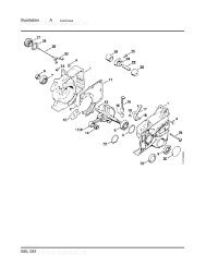
PARTS LISTS<br />
The following illustrations are for parts identification only. The<br />
removal or fitting of these parts may cause a hazard and should<br />
only be carried out by trained personnel.<br />
Page No.<br />
CHASSIS - FIXED TOWHEAD 31<br />
CHASSIS - ADJUSTABLE TOWHEAD 32<br />
CONTROL BOX 33<br />
CONTROL PANEL 34<br />
DECALS See pages 25 - 26<br />
DISCHARGE 35<br />
DRIVE TRAIN 36<br />
ELECTRICAL LAYOUT 37<br />
ENGINE 38<br />
ENGINE BAY 39<br />
FUEL TANK 40<br />
FUNNEL 41<br />
HYDRAULICS 42<br />
ROLLER BOX 43<br />
ROTOR 44<br />
ROTOR HOUSING 45<br />
V- BELT TENSIONING TABLE 46
Date Last Modified: 9th June 11<br />
21<br />
1<br />
20<br />
17<br />
38<br />
29<br />
10<br />
11<br />
49 50<br />
24<br />
16<br />
36<br />
x2<br />
18<br />
2<br />
47<br />
33<br />
12<br />
36<br />
4<br />
CHASSIS - FIXED TOWHEAD 31<br />
20<br />
19<br />
19<br />
14<br />
13<br />
28<br />
39<br />
4<br />
7<br />
10<br />
9<br />
15<br />
6<br />
5<br />
4<br />
10<br />
4<br />
14<br />
3<br />
22<br />
11<br />
46<br />
49 36<br />
25<br />
40<br />
23<br />
36<br />
43<br />
26<br />
41<br />
8<br />
9<br />
30<br />
6<br />
19<br />
4<br />
42<br />
4<br />
4<br />
44<br />
37<br />
34<br />
31<br />
10<br />
4<br />
8<br />
35<br />
11<br />
45<br />
27<br />
28 32<br />
Item Part No Part Name Q’ty<br />
35 1932 Wheel 3<br />
36 0839 M10 C Washer 14<br />
37 0350 M8/25 Bolt 2<br />
38 1036 M10 Brake Adjuster Nut 1<br />
39 1054 Brake Rod 1<br />
40 0382 M10/30 Bolt 4<br />
41 079F Nut Ball 1<br />
42 1501 M10 Plain 1/2 Nut 1<br />
43 0358 Catch Plate 1<br />
44 0067 Pop Rivet 4<br />
45 2963 Catch 1<br />
46 3043FS Outer Beam Handle 2<br />
47 17501 Jockey Wheel Clamp 1<br />
48 0878 M10/20 Bolt 2<br />
49 4345 M10 P Nyloc Nut 6<br />
50 0701 M10 A Washer 12<br />
Item Part No Part Name Q’ty<br />
18 4210 Battery 1<br />
19 0360 M10/25 Bolt 8<br />
20 0313 M12/100 4<br />
21 17478 Jockey Wheel 1<br />
22 17474FB Inner Chassis Beam O/S 1<br />
23 19076FB Outer Chassis Beam O/S 1<br />
24 1520 M10/45 Bolt 2<br />
25 19078F Offside Mudguard 1<br />
26 17522FB Tool Box Lid 1<br />
27 17494 Axle 1<br />
28 0479 M8 P Nyloc Nut 4<br />
29 17493 Tow Head 1<br />
30 0354 M8/60 Bolt 1<br />
31 1682 Threaded Stand Off 1<br />
32 2633 Wind Down Jack Stand 1<br />
33 18035FS Battery Support Bracket 1<br />
34 1683M Plain Stand Off 1<br />
Item Part No Part Name Q’ty<br />
1 19075FB Outer Chassis Beam N/S 1<br />
2 17475FB Inner Chassis Beam N/S 1<br />
3 0352 M8/40 Bolt 2<br />
4 0712 M8 C Washer 24<br />
5 19056 Lightboard 1<br />
6 0346 M8/20 Bolt 5<br />
7 19074FB Lightboard Bracket 1<br />
8 0481 M8 T Nyloc Nut 3<br />
9 0429 M12/35 Bolt 12<br />
10 0704 M12 C Washer 40<br />
11 0644 M12 P Nyloc Nut 12<br />
12 19077FB Nearside Mudguard 1<br />
13 1830FB Cross Beam 1<br />
14 18037 M8/12 Bolt 8<br />
15 1644 AV Mount 4<br />
16 0052 M10 T Nyloc Nut 2<br />
17 18036FB Battery Cover 1
29<br />
21<br />
1<br />
38<br />
x4<br />
20<br />
17<br />
49<br />
16<br />
51<br />
CHASSIS - ADJUSTABLE TOWHEAD 32<br />
47<br />
36<br />
x2<br />
18<br />
2<br />
36<br />
33<br />
12<br />
24<br />
4<br />
52<br />
50<br />
19<br />
14<br />
28<br />
10<br />
13<br />
39<br />
11<br />
4<br />
15<br />
9<br />
7<br />
6<br />
4<br />
22<br />
5<br />
14<br />
10<br />
11<br />
4<br />
3<br />
46<br />
25<br />
40<br />
49 36<br />
23<br />
43<br />
36<br />
26<br />
8<br />
4<br />
19<br />
9<br />
41<br />
30<br />
6<br />
42<br />
44<br />
10<br />
4<br />
4<br />
37<br />
35<br />
11<br />
34<br />
31<br />
4<br />
45<br />
27<br />
8<br />
Date Last Modified: 7th July 11<br />
28 32<br />
Item Part No Part Name Q’ty<br />
37 0350 M8/25 Bolt 2<br />
38 1036 M10 Brake Adjuster Nut 1<br />
39 19585 Brake Rod 1<br />
40 0382 M10/30 Bolt 4<br />
41 079F Nut Ball 1<br />
42 1501 M10 Plain 1/2 Nut 1<br />
43 0358 Catch Plate 1<br />
44 0067 Pop Rivet 4<br />
45 2963 Catch 1<br />
46 3043FS Outer Beam Handle 2<br />
47 17501 Jockey Wheel Clamp 1<br />
48 0878 M10/20 Bolt 2<br />
49 4345 M10 P Nyloc Nut 6<br />
50 0701 M10 A Washer 12<br />
51 0415 Heavy Washer 4<br />
52 0702 M12 A Washer 4<br />
Item Part No Part Name Q’ty<br />
19 0360 M10/25 Bolt 8<br />
20 4333 M12/170 4<br />
21 17478 Jockey Wheel 1<br />
22 17474FB Inner Chassis Beam O/S 1<br />
23 19572FB Outer Chassis Beam O/S 1<br />
24 1520 M10/45 Bolt 2<br />
25 19078F Offside Mudguard 1<br />
26 17522FB Tool Box Lid 1<br />
27 17494 Axle 1<br />
28 0479 M8 P Nyloc Nut 4<br />
29 19583 Tow Head 1<br />
30 0354 M8/60 Bolt 1<br />
31 1682 Threaded Stand Off 1<br />
32 2633 Wind Down Jack Stand 1<br />
33 18035FS Battery Support Bracket 1<br />
34 1683M Plain Stand Off 1<br />
35 1932 Wheel 3<br />
36 0839 M10 C Washer 14<br />
Item Part No Part Name Q’ty<br />
1 19571FB Outer Chassis Beam N/S 1<br />
2 17475FB Inner Chassis Beam N/S 1<br />
3 0352 M8/40 Bolt 2<br />
4 0712 M8 C Washer 24<br />
5 19619 Lightboard 1<br />
6 0346 M8/20 Bolt 5<br />
7 19074FB Lightboard Bracket 1<br />
8 0481 M8 T Nyloc Nut 3<br />
9 0429 M12/35 Bolt 12<br />
10 0704 M12 C Washer 34<br />
11 0644 M12 P Nyloc Nut 12<br />
12 19077FB Nearside Mudguard 1<br />
13 1830FB Cross Beam 1<br />
14 18037 M8/12 Bolt 8<br />
15 1644 AV Mount 4<br />
16 0052 M10 T Nyloc Nut 2<br />
17 18036FB Battery Cover 1<br />
18 4210 Battery 1
15<br />
16<br />
17<br />
18<br />
14<br />
13<br />
11<br />
10<br />
Item Part No Part Name Q’ty<br />
1 2794FB Control Box Cover 1<br />
2 2803 M10/240 Bolt 1<br />
3 0839 M10 C Washer 2<br />
4 4345 M10 P Nyloc Nut 1<br />
5 2795FB Control Box Base 1<br />
6 0709 M6 C Washer 4<br />
7 1658 M6/12 Bolt 4<br />
8 2853 Stop Switch 1<br />
9 2796FS Finger Plate 2<br />
10 2834 AV Mount 2<br />
11 2804 Bush M10 Top Hat 4<br />
12 2807 AV Mount 20 x 16 2<br />
12<br />
9<br />
19<br />
CONTROL BOX 33<br />
8<br />
2<br />
23<br />
3<br />
20<br />
5<br />
21 22<br />
Item Part No Part Name Q’ty<br />
13 0857 M5 A Washer 2<br />
14 18103 M5/8 Pan Pozi 2<br />
15 18168 M4/35 Pan Pozi 4<br />
16 1348 Limit Switch 2<br />
17 18100 M4 Washer 6<br />
18 18235 M4 P Nyloc Nut 6<br />
19 made in production 65mm Spacer 1<br />
20 2793FB Bracket Mounting Control Box 1<br />
21 0712 M8 C Washer 2<br />
22 0344 M8/16 Bolt 4<br />
23 0711 M8 A Washer 2<br />
6<br />
1<br />
7<br />
Date Last Modified: 21st July 05<br />
4
0<br />
1<br />
1<br />
2<br />
2<br />
3<br />
Item Part No Part Name Q’ty<br />
1 18107 M6 Wing Nut 3<br />
2 18106 M6 Split Washer 3<br />
3 0709 M6 C Washer 11<br />
4 1972 Electrical Cover 1<br />
5 2725 Electrical Cover Stand Off 3<br />
6 0391 M6 T Nyloc Nut 5<br />
7 0438 M6/16 Pan Pozi 3<br />
8 Supp’d with loom Relay 2<br />
9 0857 M5 A Washer 9<br />
10 0236 M5 P Nyloc Nut 5<br />
11 2958FS Electrical Panel 1<br />
20<br />
CONTROL PANEL 34<br />
4<br />
18<br />
5<br />
9<br />
16<br />
3<br />
22<br />
17<br />
6<br />
7<br />
19<br />
3<br />
8<br />
6<br />
Date Last Modified: 20th March 08<br />
Item Part No Part Name Q’ty<br />
12 4033 M5 AV Mount 5<br />
13 Supp’d with loom LED 2<br />
14 Supp’d with engine Ignition Switch 1<br />
15 0327 Hours Counter 1<br />
16 Supp’d with loom Fuse 2<br />
17 1151 Countersunk Pop Rivet 1<br />
18 0435 M5/16 Pan Pozi 4<br />
19 18405 H-Box 1<br />
20 2951 Control Panel Decal 1<br />
21 3024 M5 Spring Washer 5<br />
22 18398 Mounting Bracket 2<br />
10<br />
21 9<br />
11<br />
12<br />
13<br />
15<br />
14
8<br />
9<br />
15<br />
16<br />
10<br />
11<br />
13<br />
12<br />
14<br />
Date Last Modified: 18th March 2010<br />
DISCHARGE 35<br />
1<br />
7<br />
Item Part No Part Name Q’ty<br />
1 0904FO Discharge Tube 1<br />
2 0523FO Discharge Bucket 1<br />
3 0045 M12 T Nyloc Nut 2<br />
4 0702 M12 A Washer 2<br />
5 19282 M12/30 Cup Square 1<br />
6 19283 M12/40 Cup Square 1<br />
7 0134 Black Handle Grip 1<br />
8 1649MS Discharge Clamp Handle 1<br />
9 4109M M16 Clamp Nut 1<br />
10 4131 Roll Pin 1<br />
11 0434 M16/70 Hex Bolt 1<br />
12 1354 M16 C Washer 1<br />
13 2837M Clamp Nut Small 1<br />
14 1511 M16 P Nyloc Nut 1<br />
15 0832 M24 Washer 1<br />
16 0333 M16/60 Hex Bolt 1<br />
2<br />
3<br />
4<br />
6<br />
3<br />
5<br />
4
4<br />
5<br />
Item Part No Part Name Q’ty<br />
1 17322 Vee Belt 1232 XPA 3<br />
2 4327 Taper Lock Bush 2517 50 mm 1<br />
3 17321 Pulley 280 x 3 1<br />
4 2984M Key 54 x 14 x 9 1<br />
5 17314 Pulley Engine 168 x 4 1<br />
3<br />
DRIVE TRAIN 36<br />
2<br />
1<br />
Date Last Modified: 16th Sept 05
Date Last Modified: 20th March 08<br />
1<br />
Item Part No Part Name Q’ty<br />
1 1406 Safety Switch Loom 1<br />
2 1975 Control Box Loom 1<br />
3 18482 Engine Loom 1<br />
ELECTRICAL LAYOUT 37<br />
2<br />
5 4<br />
3<br />
Item Part No Part Name Q’ty<br />
4 1375 + VE Battery Cable 1<br />
5 1376 - VE Battery Cable 1<br />
3
7<br />
4<br />
5<br />
26<br />
6<br />
7<br />
22<br />
3<br />
18<br />
Item Part No Part Name Q’ty<br />
1 4316 Air Cleaner 1<br />
2 0095 Oil Filter 1<br />
3 Air Filter 1<br />
4 4252 Directional Control Valve (DCV) 1<br />
5 19157FB Engine Bracket Nearside 1<br />
6 0711 M8 A Washer 7<br />
7 0346 M8/20 Bolt 3<br />
8 19157FB Engine Bracket Offside 1<br />
9 4319 Radiator Kit 1<br />
10 4313 Engine 1<br />
11 0350 M8/25 Bolt 2<br />
12 2946 Throttle Assembly 1<br />
13 0304 M10/25 Fine Thread Socket Cap 16<br />
14 0085 Fuel Filter 1<br />
15 2954FS Throttle Cable Bracket 1<br />
16<br />
6<br />
17<br />
10<br />
1<br />
2<br />
15<br />
ENGINE 38<br />
10<br />
29<br />
12<br />
26<br />
30<br />
1<br />
20<br />
27<br />
28<br />
21<br />
8<br />
9<br />
19<br />
25<br />
Date Last Modified: 17th Dec 09<br />
Item Part No Part Name Q’ty<br />
16 17314 Pulley Engine 168 x 4 1<br />
17 0352 M8/40 Bolt 1<br />
18 0481 M8 T Nyloc Nut 1<br />
19 0392 M6 Plain Nut 4<br />
20 4297FB Air Intake Tube 1<br />
21 4335 Radiator Fan Guard 1<br />
22 4054 M10/35 Fine Thread Socket Cap 6<br />
23 0437 M6/16 Bolt 4<br />
24 0709 M6 C Washer 8<br />
25 18106 M6 Spring Washer 4<br />
26 18629FB Engine Bracket Base 2<br />
27 0332 M12/90 Bolt 4<br />
28 18522 AV Mount 4<br />
29 0704 M12 C Washer 4<br />
30 0644 M12 P Nyloc Nut 4<br />
24<br />
11<br />
x4<br />
23<br />
6<br />
14<br />
13
Date Last Modified: 11th Sept 08<br />
23<br />
1 5<br />
32 40<br />
12 13<br />
31<br />
6<br />
Item Part No Part Name Q’ty<br />
1 2950 Throttle Decal 1<br />
2 18327FB Exhaust Muffler Complete 1<br />
3 0344 M8/16 Bolt 2<br />
4 0711 M8 A Washer 2<br />
5 0438 M6/16 Pan Pozi 3<br />
6 0709 M6 C Washer 5<br />
7 0391 M6 T Nyloc Nut 3<br />
8 0066 Pop Rivet 5 x 6 2<br />
9 4088 Catch Plate 1<br />
10 0607FO Access Cover 1<br />
11 4270FO Top Bonnet 1<br />
12 1757 M8 P Nyloc Nut 8<br />
13 0769 M8 C Washer 22<br />
14 0765 Side Panel 2<br />
15 0825FS Side Panel Handle 2<br />
16 0348 M8/20 Skt Csk Bolt 4<br />
17 0704 M12 C Washer 14<br />
18 0318 M12/20 Bolt 2<br />
30<br />
14<br />
ENGINE BAY 39<br />
27<br />
6<br />
7<br />
15 17 18<br />
16<br />
13 12<br />
29<br />
x3<br />
2<br />
x6<br />
33<br />
17<br />
3<br />
4<br />
24<br />
17<br />
26<br />
34<br />
12<br />
13<br />
13<br />
26<br />
Item Part No Part Name Q’ty<br />
19 0067 Pop Rivet 4.8 x 12 3<br />
20 18580FO Radiator Shroud 1<br />
21 0235 Catch 1<br />
22 0350 M8/25 Bolt 2<br />
23 4315 In-Line Fuel Filter 1<br />
24 0429 M12/35 Bolt 6<br />
25 0431 M12/40 Bolt 6<br />
26 0481 M8 T Nyloc Nut 10<br />
27 2955FO Engine Base Guard 1<br />
28 1984FS Engine Guard Bracket 2<br />
29 0644 M12 P Nyloc Nut 6<br />
30 4314 Fuel Pump 1<br />
31 0437 M6/16 Bolt 2<br />
32 2851 Clip Fuel Filter 1<br />
33 4253 Domed Blanking Plug 1<br />
34 4320 Reserve Tank 1<br />
35 18581FO Shroud Radiator with Grille 1<br />
36 0346 M8/20 Bolt 2<br />
8<br />
9<br />
10<br />
11<br />
28<br />
20 21 19<br />
x2<br />
13<br />
x2<br />
22<br />
13<br />
35<br />
36
6<br />
Item Part No Part Name Q’ty<br />
1 1374 Locking Tank Cap 1<br />
2 1658 M6/12 Bolt 6<br />
3 0709 M6 C Washer 6<br />
4 2617FS Fuel Tank Filler Assy 1<br />
5 2811FB Funnel Support 1<br />
6 18392K Fuel Tank Kit (inc. parts 11-12, 17-21) 1<br />
7 0479 M8 P Nyloc Nut 2<br />
8 0712 M8 C Washer 4<br />
9 1989FS Bracket Tank Front 1<br />
10 1990FS Bracket Tank Rear 1<br />
11 0396 3/8 Dowty Washer 1<br />
12 0211 3/8 Drain Plug 1<br />
11<br />
12<br />
15<br />
FUEL TANK 40<br />
1<br />
2<br />
3<br />
4<br />
5<br />
8<br />
10<br />
17<br />
7<br />
13<br />
14<br />
19<br />
9<br />
Date Last Modified: 9th June 08<br />
Item Part No Part Name Q’ty<br />
13 0360 M10/25 Bolt 4<br />
14 0839 M10 C Washer 4<br />
15 0346 M8/20 Bolt 2<br />
16 0481 M8 T Nyloc Nut 2<br />
17 2897M Pick Up Weight 1<br />
18 2896 Copper Washer 2<br />
19 0389 8 MM Rubber Pipe 1<br />
20 1992 Tail Hose 2<br />
21 18568 Reducer Bush 1<br />
22 0711 M8 A Washer 2<br />
23 0152 3/4” Dowty Washer 1<br />
22<br />
20<br />
16<br />
18<br />
21<br />
23<br />
20
Date Last Modified: 9th Oct 08<br />
31<br />
14<br />
32<br />
22<br />
30<br />
37<br />
29<br />
10<br />
40<br />
7<br />
18<br />
7<br />
39<br />
26<br />
15 16<br />
3<br />
Item Part No Part Name Q’ty<br />
1 2809F Control Box (detail on page 33) 1<br />
2 1933FS Spare Wheel Bracket 1<br />
3 0045 M12 T Nyloc Nut 6<br />
4 0702 M12 A Washer 4<br />
5 0320 M12/25 Cup Square 4<br />
6 1932 Spare Wheel 1<br />
7 0704 M12 C Washer 11<br />
8 0342 M8/10 Bolt 6<br />
9 1644 M8 Anti-Vibration Mount 3<br />
10 0712 M8 C Washer 8<br />
11 1601 Nylon Piston 2<br />
12 1603 Die Spring 2<br />
13 0644 M12 P Nyloc Nut 3<br />
14 0429 M12/35 Bolt 2<br />
15 1605M Stainless Spacer 2<br />
16 1599 Bearing Washer 2<br />
17 2913FO Funnel 1<br />
18 1348 Limit Switch 1<br />
19 1520 M10/45 Bolt 2<br />
20 1591 Nylon Spacer 2<br />
21 4206 Nylon Bush 1<br />
12<br />
34<br />
32<br />
24<br />
11<br />
33<br />
FUNNEL 41<br />
36<br />
17<br />
21<br />
10 41<br />
10<br />
40<br />
8<br />
9<br />
38<br />
20<br />
28<br />
19<br />
1<br />
27<br />
Item Part No Part Name Q’ty<br />
22 0479 M8 P Nyloc Nut 1<br />
23 2923 Hinge Pin 2<br />
24 2986 1/2” Spring Bolt 2<br />
25 1276 Split Pin 2<br />
26 1598F Safety Bar 1<br />
27 0391 M6 T Nyloc Nut 8<br />
28 4344 M10 C Repair Washer 2<br />
29 0178 Rubber End Stop 1<br />
30 2727 Actuator Bracket 1<br />
31 0437 M6/16 Bolt 2<br />
32 0709 M6 C Washer 10<br />
33 2914FR Feed Tray 1<br />
34 0437 M6/16 Bolt 8<br />
35 0046 M12 Plain Nut 4<br />
36 18115 M8/50 Csk Soc. 1<br />
37 1006 M4/30 Pan Pozi 2<br />
38 4345 M10 P Nyloc Nut 1<br />
39 2493 Rubber Cap 2<br />
40 1337 Rubber Cap 2<br />
41 0481 M8 T Nyloc Nut 1<br />
2<br />
3<br />
4<br />
5<br />
7<br />
35<br />
25<br />
23<br />
7<br />
13<br />
6
10<br />
22<br />
11<br />
18<br />
19<br />
22<br />
9<br />
21<br />
9<br />
12<br />
16<br />
15<br />
20<br />
Item Part No Part Name Q’ty<br />
1 1434 Return Filter 1<br />
2 0100 Filter 1<br />
3 0350 M8/25 Bolt 2<br />
4 0711 M8 A Washer 2<br />
5 1658 M6/12 Bolt 8<br />
6 1702FS Tank Top Plate 1<br />
7 0152 3/4” Dowty Seal 2<br />
8 0225 3/8” - 3/4” BSP Adapter 1<br />
9 4243 3/8” Hose, Pump to DCV 1<br />
10 0161 3/8” - 3/8” Adapter 5<br />
11 0396 3/8” Dowty Seal 6<br />
12 4252 Directional Control Valve (DCV) 1<br />
13 1660 Pump 1<br />
14 0026 1/2” - 3/8” BSP Adapter 4<br />
11<br />
10<br />
19<br />
HYDRAULICS 42<br />
15<br />
13<br />
18<br />
14<br />
17<br />
17<br />
21<br />
11<br />
24<br />
8<br />
23<br />
1<br />
7<br />
7<br />
Date Last Modified: 5th Dec 06<br />
Item Part No Part Name Q’ty<br />
15 0398 1/2” Dowty Washer 5<br />
16 2982B Motor 2<br />
17 2885 3/8” Hose, Top Motor to Btm Motor 1<br />
18 3060 3/8” Hose, Top Motor to DCV 1<br />
19 2973 3/8” Hose, Bottom Motor to DCV 1<br />
20 1583 1/2” - 3/4” BSP Adapter 1<br />
21 2830 3/4” Hose, Hyd Tank to Pump 1<br />
22 4244 3/8” Hose, Hyd Filter to DCV 1<br />
23 1766 3/4” - 3/4” BSP Adapter 1<br />
24 0211 3/8” BSP Blanking Plug 1<br />
25 1703 Hydraulic Oil Tank 1<br />
26 4219 3/4” Tapered Blanking Plug 1<br />
27 1067 Breather Filter 1<br />
27<br />
5<br />
6<br />
2<br />
3<br />
4<br />
26<br />
25
28<br />
7<br />
2<br />
3<br />
2<br />
27<br />
47<br />
6<br />
8<br />
4<br />
31<br />
1<br />
5<br />
32<br />
15 16<br />
12<br />
22 23<br />
x8<br />
x6<br />
52<br />
53<br />
36<br />
35<br />
9<br />
18<br />
x8<br />
13<br />
{<br />
29<br />
33<br />
14<br />
34<br />
19<br />
x2<br />
17<br />
55 54<br />
46<br />
ROLLER BOX 43<br />
x4<br />
56<br />
10<br />
x6<br />
50<br />
51<br />
20<br />
11<br />
19<br />
x4<br />
37<br />
45<br />
41<br />
38<br />
48<br />
16<br />
26 19<br />
24<br />
21<br />
22<br />
25<br />
44<br />
19<br />
57<br />
30<br />
x4 Road Tow machines only<br />
34<br />
x2 Tracked machines only<br />
Item Part No Part Name Q’ty<br />
39 2783FS Fitting Bracket Short 4<br />
40 0351 M8/30 Bolt 1<br />
41 4342 M8/30 CSK Screw 1<br />
42 0479 M8 P Nyloc Nut 2<br />
43 0712 M8 C Washer 2<br />
44 18268FS Fitting Bracket Long 1<br />
45 0330 M12/70 Bolt 4<br />
46 4340 M12/50 Caphead 4<br />
47 1840FS Roller Box Top 1<br />
48 0356 Roller Box Stud 4<br />
49 0711 M8 A Washer 1<br />
50 2888 Layflat Spring Protector 4<br />
51 0839 M10 C Washer 8<br />
52 4135M Spacer Disc 4<br />
53 4224M Anvil Primary Right Side 1<br />
54 17374P Stub Shaft Profile 2<br />
55 17375M Stub Shaft 2<br />
56 0429 M12/35 Bolt 8<br />
57 M12/260 Threaded Rod 2<br />
39<br />
14 15<br />
42<br />
40<br />
x2<br />
43<br />
17<br />
42<br />
49<br />
x4<br />
56<br />
55 54<br />
Date Last Modified: 12th Nov 09<br />
Item Part No Part Name Q’ty<br />
20 0481 M12/30 Bolt 2<br />
21 1525 M10/40 Caphead 3<br />
22 1985 M12/30 Caphead 6<br />
23 2982B Hydraulic Motor 2<br />
24 3025MS Bracket Motor AV Mount 1<br />
25 2731M Adapter Spline 1<br />
26 0985 Straight Grease Nipple 1<br />
27 19052 Spring 4<br />
28 0878 M10/20 Bolt 4<br />
29 4341 M12/150 Threaded Bar 1<br />
30 0045 M12 T Nyloc Nut 4<br />
31 1898M Damper Stop 2<br />
32 18491FO Roller Box 190mm 1<br />
33 2733M Bearing Roller Motor Side 1<br />
34 0046 M12 Plain Nut 4<br />
35 1517 M12/40 Caphead 2<br />
36 4223M Anvil Primary Left Side 1<br />
37 1284 M16 T Nyloc Nut 4<br />
38 1143 M16 A Washer 4<br />
Item Part No Part Name Q’ty<br />
1 0382 M10/30 Bolt 2<br />
2 0701 M10 A Washer 8<br />
3 0052 M10 T Nyloc Nut 2<br />
4 2748FS Short Spring Hanger 1<br />
5 0305 M10/25 Caphead 4<br />
6 2940FS Top Roller Slide Assembly 1<br />
7 0481 M8 T Nyloc Nut 4<br />
8 1526 M12/25 Caphead 2<br />
9 1768 AV Mount 4<br />
10 1812 M10/35 Bolt 8<br />
11 3026 AV Bush Concentric 8<br />
12 3009 Slide Plug 8<br />
13 2732M Adapter Spline 6B 1<br />
14 1947M Roller Hub 190 2<br />
15 1948MH Roller Blade 190 12<br />
16 0428 M12/30 CSK Blade Bolts 24<br />
17 0788 Bearing Plastic Bush 4<br />
18 0986 45o Grease Nipple 1<br />
19 0702 M12 A Washer 31
15<br />
14<br />
20<br />
19<br />
12<br />
x6<br />
11<br />
10<br />
8<br />
Date Last Modified: 13th Feb 09<br />
18<br />
17<br />
9<br />
16<br />
ROTOR 44<br />
x8<br />
13<br />
6<br />
5<br />
4<br />
7<br />
3<br />
2<br />
1<br />
Item Part No Part Name Q’ty<br />
11 0355 M8/16 CSK Bolt 4<br />
Item Part No Part Name Q’ty<br />
1 0360 M10/25 Bolt 1<br />
12 2902MS Bolt Plate 2<br />
13 1940MS Bearing Spacer 1<br />
2 0839 M10 C Washer 1<br />
3 17350M Rotor Shaft 1<br />
14 1218 M16 Hardened Washer 4<br />
15 1284 M16 T Nyloc Nut 4<br />
4 1527 M8/25 Caphead 8<br />
5 1937M Bearing Cap 1<br />
16 1862 Bearing 6308 1<br />
17 1893 Nut M39/4 1<br />
6 2943 Oil Seal 1<br />
7 1939 Bearing 6309 1<br />
18 2983MS Drive Adapter 1<br />
19 0701 M10 A Washer 6<br />
8 18712M Blade Bolt 2<br />
9 18513M Rotor Disc 1<br />
20 4054 M10/35 Finethread Capheads 6<br />
10 18692MH 5” Blade 2
1<br />
Date Last Modified: 14th Sept 09<br />
3<br />
Item Part No Part Name Q’ty<br />
1 1906FO Guard Roller Box Near Side 1<br />
2 0878 M10/20 Bolt 6<br />
3 0360 M10/25 Bolt 3<br />
4 0839 M10 C Washer 9<br />
5 1907FO Guard Roller Box Off Side 1<br />
6 0052 M10 T Nyloc Nut 2<br />
7 0701 M10 A Washer 2<br />
8 4066 Gas Spring Compression 1<br />
9 0528 Split Pin 1<br />
10 1943M Pin Hinge 180 mm 1<br />
11 18443FO Rotor Housing Opening 1<br />
12 2978S M16 Flange Nut 2<br />
2<br />
ROTOR HOUSING 45<br />
3<br />
4<br />
2<br />
5<br />
10<br />
6<br />
9<br />
7<br />
8<br />
21 20<br />
Item Part No Part Name Q’ty<br />
13 0178 Rubber End Stop 1<br />
14 0479 M8 P Nyloc Nut 1<br />
15 0712 M8 C Washer 2<br />
16 1691FS Switch Back Plate 1<br />
17 1868 M8 AV Mount 2<br />
18 0711 M8 A Washer 4<br />
19 1721 M8/10 Bolt 4<br />
20 1692 Limit Switch 1<br />
21 1006 M4/30 Pan Pozi 2<br />
22 18442FO Rotor Housing Fixed 1<br />
23 2819FS Fitting Bracket 1<br />
16<br />
13<br />
23<br />
17<br />
11<br />
18<br />
22<br />
19<br />
12<br />
14<br />
15
TIMBERWOLF V-BELT TENSIONING DATA TABLE<br />
METHOD:<br />
1. SET THE DEFLECTION DISTANCE ON THE LOWER SCALE OF THE TENSION GUAGE<br />
SO THAT THE UNDERSIDE OF THE 'O'-RING EQUALS THE 'h' VALUE GIVEN IN THE<br />
TABLE BELOW<br />
V-BELT TENSIONING TABLE 46<br />
TIPS ON BELT TIGHTENING:<br />
A) THERE WILL NORMALLY BE A RAPID DROP IN TENSION DURING THE<br />
RUN-IN PERIOD FOR NEW BELTS. WHEN NEW BELTS ARE FITTED, CHECK THE<br />
TENSION EVERY 2-3 HOURS & ADJUST UNTIL THE TENSION REMAINS<br />
CONSTANT<br />
2. ENSURE THAT THE DEFLECTION FORCE SCALE IS ZERO'D BY PUSHING THE UPPER<br />
'O'-RING ALL THE WAY DOWN<br />
=<br />
=<br />
3. PLACE THE TENSION GUAGE IN THE CENTRE OF THE BELT SPAN AS SHOWN IN<br />
THE DIAGRAM LEFT<br />
B) THE BEST TENSION FOR V-BELT DRIVES IS THE LOWEST TENSION AT<br />
WHICH THE BELTS DO NOT SLIP OR RATCHET UNDER THE HIGHEST LOAD<br />
CONDITION<br />
4. PRESS DOWNWARDS ON THE RUBBER BUFFER, DEFLECTING THE BELT UNTIL THE<br />
UNDERSIDE OF THE LOWER O'-RING IS LEVEL WITH THE BELT BEHIND (USE A<br />
STRAIGHT EDGE IF THERE IS ONLY 1 BELT)<br />
h<br />
C) TOO MUCH TENSION SHORTENS BELT & BEARING LIFE<br />
D) TOO LITTLE TENSION WILL AFFECT THE PERFORMANCE OF YOUR MACHINE<br />
ESPECIALLY IN RESPECT OF NO-STRESS DEVICES<br />
5. TAKE THE READING FROM THE DEFLECTION SCALE OF THE TENSION METER<br />
(READ AT THE LOWER EDGE OF THE 'O'-RING) & COMPARE THIS VALUE WITH<br />
THAT GIVEN IN THE TABLE BELOW<br />
E) ENSURE THAT BELT DRIVES ARE KEPT FREE OF ANY FOREIGN MATERIALS<br />
6. TIGHTEN OR LOOSEN BELTS AS REQUIRED FOLLOWING PROCEDURE GIVEN IN THE<br />
OPERATOR'S MANUAL<br />
F) IF A BELT SLIPS - TIGHTEN IT!<br />
TENSION GUAGES ARE AVAILABLE FROM TIMBERWOLF SPARES, QUOTING PART No. 18091<br />
S425/S426<br />
SHREDDER<br />
230TR 250DH PTO100 PTO150 PTO300<br />
190TFTR<br />
190TVGTR<br />
13/75G 18/100G 125PH 150DH/DHB 150FTR 150VTR 190DH 190FTR 190TDH<br />
TW MODEL No.:<br />
Gates Super<br />
HC-MN<br />
N/A<br />
Gates Super<br />
HC-MN<br />
Gates Super<br />
HC-MN<br />
Gates Quad<br />
Power II<br />
Gates Super<br />
HC-MN<br />
Gates Super<br />
HC-MN<br />
Gates Super<br />
HC-MN<br />
Gates Super<br />
HC-MN<br />
Gates Super<br />
HC-MN<br />
Gates Super<br />
HC-MN<br />
Gates Super<br />
HC-MN<br />
Gates Super<br />
HC-MN<br />
Gates Super<br />
HC-MN<br />
Gates Super<br />
HC-MN<br />
Gates Super<br />
HC-MN<br />
Belt Mfr / Type<br />
Belt Pitch Designation SPA SPA SPA SPA SPA SPA SPA SPA SPA SPA SPB XPB SPA SPA SPB<br />
Belt Length 900.0 1060.0 1060.0 1060.0 1060.0 1060.0 1232.0 1232.0 1232.0 1232.0 1950.0 3350.0 900.0 900.0 2120.0<br />
Belt deflection = h 4.0 4.0 4.0 4.0 4.0 4.0 4.0 4.0 4.0 4.0 6.0 10.0 4.0 4.0 8.0<br />
ROTOR BELTS<br />
3.4 - 3.6 3.1 - 3.3 3.0 - 3.2 4.3 - 4.5 4.3 - 4.5 4.3 - 4.5 3.3 - 3.5 3.3 - 3.5 3.9 - 4.1 3.9 - 4.1 3.4 - 3.6 3.5 - 3.7* 3.3 - 3.5 3.8 - 4.0 3.3 - 3.5*<br />
New belt<br />
Force reading<br />
(Kgf)<br />
3.0 - 3.2 2.8 - 3.0 2.7 - 2.9 3.7 - 4.0 3.7 - 4.0 3.7 - 4.0 2.8 - 3.0 2.8 - 3.0 3.4 - 3.6 3.4 - 3.6 3.0 - 3.2 3.1 - 3.3* 2.9 - 3.0 3.3 - 3.5 2.9 - 3.1*<br />
Used belt<br />
N/A<br />
Gates Super<br />
HC-MN<br />
Gates Super<br />
HC-MN<br />
N/A N/A<br />
Gates Super<br />
HC-MN<br />
Gates Super<br />
HC-MN<br />
N/A<br />
Gates Super<br />
HC-MN<br />
N/A<br />
Gates Super<br />
HC-MN<br />
Gates Super<br />
HC-MN<br />
N/A<br />
Gates Super<br />
HC-MN<br />
Belt Mfr / Type N/A N/A<br />
Belt Pitch Designation SPA SPA SPA SPA SPA SPA SPA SPA<br />
Belt Length 950.0 900.0 900.0 925.0 925.0 950.0 950.0 1000.0<br />
Belt deflection = h 4.0 4.0 4.0 4.0 4.0 4.0 4.0 4.0<br />
PUMP BELT<br />
1.9 - 2.0 2.3 - 2.4 2.3 - 2.4 2.3 - 2.4 2.3 - 2.4 1.5 - 1.6 2.0 - 2.2 1.9 - 2.0<br />
New belt<br />
1.7 - 1.8 2.0 - 2.1 2.0 - 2.1 2.0 - 2.2 2.0 - 2.2 1.3 - 1.4 1.8 - 2.0 1.7 - 1.8<br />
Used belt<br />
Force reading<br />
(Kgf)<br />
Ver 2.0 - 12-10-07<br />
* DUE TO THE EXTENDED BELT SPAN LENGTHS ON THE 250DH & S425/S426 SHREDDER, THE FORCE READINGS ARE INCREASED BY 0.5Kgf OVER THE DESIGN IQ OUTPUTS