

Centrifugal Fan Class IV - Greenheck Fan Corporation - Building ...
Centrifugal Fan Class IV - Greenheck Fan Corporation - Building ...
Centrifugal Fan Class IV - Greenheck Fan Corporation - Building ...

Create successful ePaper yourself
Turn your PDF publications into a flip-book with our unique Google optimized e-Paper software.
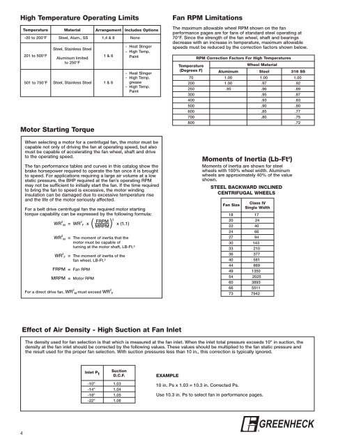
High Temperature Operating Limits<br />
4<br />
Temperature Material Arrangement Includes Options<br />
-20 to 200°F Steel, Alum., SS 1,4 & 8 None<br />
201 to 500°F<br />
501 to 750°F<br />
Steel, Stainless Steel<br />
Aluminum limited<br />
to 250°F<br />
Steel, Stainless Steel<br />
Motor Starting Torque<br />
1 & 8<br />
1 & 8<br />
- Heat Slinger<br />
- High Temp.<br />
Paint<br />
- Heat Slinger<br />
- High Temp.<br />
grease<br />
- High Temp.<br />
Paint<br />
When selecting a motor for a centrifugal fan, the motor must be<br />
capable not only of driving the fan at operating speed, but also<br />
must be capable of accelerating the fan wheel, shaft and drive<br />
to the operating speed.<br />
The fan performance tables and curves in this catalog show the<br />
brake horsepower required to operate the fan once it is brought<br />
to speed. For applications requiring a large air volume at a low<br />
static pressure, the BHP required at the fan’s operating RPM<br />
may not be sufficient to initially start the fan. If the time required<br />
to bring the fan to speed is excessive, the motor winding<br />
insulation can be damaged due to excessive temperature rise<br />
and the life of the motor seriously affected.<br />
For a belt drive centrifugal fan the required motor starting<br />
torque capability can be expressed by the following formula:<br />
WR 2<br />
M = WR 2<br />
F x<br />
( MRPM)<br />
FRPM 2<br />
x (1.1)<br />
WR 2<br />
M = The moment of inertia that the<br />
motor must be capable of<br />
turning at the motor shaft, LB-Ft. 2<br />
WR 2<br />
F = The moment of inertia of the<br />
fan wheel, LB-Ft. 2<br />
FRPM = <strong>Fan</strong> RPM<br />
MRPM = Motor RPM<br />
For a direct drive fan, WR 2<br />
M must exceed WR 2<br />
F<br />
Effect of Air Density - High Suction at <strong>Fan</strong> Inlet<br />
<strong>Fan</strong> RPM Limitations<br />
The maximum allowable wheel RPM shown on the fan<br />
performance pages are for fans of standard steel operating at<br />
70°F. Since the strength of the fan wheel, shaft and bearings<br />
decrease with an increase in temperature, maximum allowable<br />
speeds must be reduced by the correction factors shown below.<br />
RPM Correction Factors For High Temperatures<br />
Temperature<br />
Wheel Material<br />
(Degrees F) Aluminum Steel 316 SS<br />
70 1.00 1.00 1.00<br />
200 1.00 .97 .92<br />
250 .95 .96 .89<br />
300 .95 .87<br />
400 .93 .83<br />
500 .90 .80<br />
600 .85 .77<br />
700 .80 .75<br />
800 .72<br />
Moments of Inertia (Lb-Ft 2 )<br />
Moments of inertia are shown for steel<br />
wheels with 100% wheel width. Aluminum<br />
wheels are approximately 40% of the value<br />
shown.<br />
STEEL BACKWARD INCLINED<br />
CENTRIFUGAL WHEELS<br />
<strong>Fan</strong> Size<br />
<strong>Class</strong> <strong>IV</strong><br />
Single Width<br />
18 17<br />
20 24<br />
22 40<br />
24 66<br />
27 94<br />
30 143<br />
33 210<br />
36 377<br />
40 581<br />
44 869<br />
49 1350<br />
54 2025<br />
60 3893<br />
66 5511<br />
73 7942<br />
The density used for fan selection is that which is measured at the fan inlet. When the inlet total pressure exceeds 10" in suction, the<br />
density at the fan inlet should be corrected by the following values. These values should be multiplied to the fan static pressure and<br />
the result used for the proper fan selection. With suction pressures less than 10 in., this correction is typically ignored.<br />
Inlet P t<br />
Suction<br />
D.C.F.<br />
-10" 1.03<br />
-14" 1.04<br />
-18" 1.05<br />
-22" 1.06<br />
EXAMPLE<br />
10 in. Ps x 1.03 = 10.3 in. Corrected Ps.<br />
Use 10.3 in. Ps to select fan in performance pages.<br />
GREENHECK<br />
®