

Centrifugal Fan Class IV - Greenheck Fan Corporation - Building ...
Centrifugal Fan Class IV - Greenheck Fan Corporation - Building ...
Centrifugal Fan Class IV - Greenheck Fan Corporation - Building ...

You also want an ePaper? Increase the reach of your titles
YUMPU automatically turns print PDFs into web optimized ePapers that Google loves.
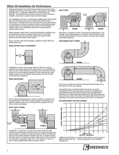
Effect Of Installation On Performance<br />
6<br />
Ratings presented in the performance tables and curves of this<br />
catalog were derived from tests made in accordance with AMCA<br />
Standard 210 – “Laboratory Methods of Testing <strong>Fan</strong>s for<br />
Ratings.” The AMCA test procedure utilizes an open inlet and a<br />
straight outlet duct to assure maximum static regain.<br />
Any installation with inlet or discharge configurations that deviate<br />
from this standard may result in reduced fan performance.<br />
Restricted or unstable flow at the fan inlet can cause pre-rotation<br />
of incoming air or uneven loading of the fan wheel yielding large<br />
system losses and increased sound levels. Free discharge or<br />
turbulent flow in the discharge ductwork will also result in<br />
system effect losses.<br />
Static pressure losses due to inlet and discharge conditions can<br />
be expressed in terms of system effect factors. The static<br />
pressure for selection of the fans equals the system static<br />
pressure plus the system effect factor.<br />
Some common inlet and discharge conditions which affect fan<br />
performance are:<br />
NON-DUCTED INLET CLEARANCE<br />
Installation of a fan with an open inlet too close to a wall or<br />
bulkhead will cause reduced fan performance. It is desirable to<br />
have one fan wheel diameter if possible and a minimum of three<br />
fourths of a wheel diameter between the fan inlet and the wall.<br />
System effect curve #3 depicts the pressure loss for one-half<br />
wheel diameter clearance.<br />
FREE DISCHARGE<br />
Free or abrupt discharge into a plenum results in a reduction in<br />
fan performance. The effect of static regain in discharge is not<br />
realized. System effect curve #2 depicts the pressure loss for<br />
free or abrupt discharge.<br />
INLET DUCT TURNS<br />
Turning<br />
Vanes<br />
1 <strong>Fan</strong><br />
Wheel<br />
Dia.<br />
1 <strong>Fan</strong><br />
Wheel<br />
Dia.<br />
GOOD POOR<br />
Installation of a duct turn or elbow too close to the fan inlet<br />
reduces fan performance because the air is loaded unevenly into<br />
the fan wheel. To achieve full fan performance there should be at<br />
least one fan wheel diameter between the turn or elbow and the<br />
fan inlet. Curve #1 shows the system effect factor when less than<br />
one diameter is provided. Note: Use of an inlet box in lieu of a<br />
turn or elbow significantly reduces system effect.<br />
INLET SPIN<br />
Inlet spin is a frequent cause of reduced fan performance. The<br />
change in fan performance is a function of the intensity of spin<br />
and not easily defined. The best solution is proper duct design<br />
and airflow patterns.<br />
DISCHARGE DUCT TURNS<br />
Duct turns located near the fan discharge should always be in<br />
the direction of the fan rotation.<br />
<strong>Fan</strong> performance is reduced when duct turns are made<br />
immediately off the fan discharge. To achieve cataloged fan<br />
performance there should be at least three equivalent duct<br />
diameters of straight ductwork between the fan discharge and<br />
any duct turns. Curve #4 shows the system effect factor for two<br />
diameters of straight ductwork and curve #2 for one diameter.<br />
SYSTEM EFFECT FACTOR CURVES<br />
STATIC PRESSURE LOSS<br />
1.2<br />
1.0<br />
0.8<br />
0.6<br />
0.4<br />
0.2<br />
0.0<br />
Rotation<br />
Rotation<br />
POOR<br />
Rotation<br />
POOR<br />
Turning<br />
Vanes<br />
Length of Straight Duct<br />
GOOD<br />
CURVE 1<br />
Rotation<br />
GOOD<br />
CURVE 2<br />
CURVE 3<br />
CURVE 4<br />
0 5 10 15 20 25 30 35 40 45<br />
FPM X 100<br />
OUTLET VELOCITY<br />
Additional information on system effect factors can be found in<br />
AMCA Publication 201 – “<strong>Fan</strong>s and Systems” and ASHRAE<br />
Handbooks.<br />
GREENHECK<br />
®