Very High Power PEBB technology - VDE
Very High Power PEBB technology - VDE
Very High Power PEBB technology - VDE

You also want an ePaper? Increase the reach of your titles
YUMPU automatically turns print PDFs into web optimized ePapers that Google loves.
<strong>Very</strong> <strong>High</strong> <strong>Power</strong> <strong>PEBB</strong> <strong>technology</strong> BRUECKNER Thomas<br />
Acknowledgements<br />
<strong>Very</strong> <strong>High</strong> <strong>Power</strong> <strong>PEBB</strong> <strong>technology</strong><br />
P. K. Steimer, O. Apeldoorn, B. Ødegård<br />
ABB Switzerland Ltd.<br />
<strong>Power</strong> Electronics and MV drives<br />
5300 Turgi - Switzerland<br />
Tel.: +41 – 58 – 589 38 88<br />
Fax: +41 – 58 – 589 25 79<br />
E-Mail: peter.steimer@ch.abb.com<br />
URL: http://www.abb.com<br />
S. Bernet, T. Brückner<br />
Berlin University of Technology<br />
FG <strong>Power</strong> Electronics<br />
10587 Berlin - Germany<br />
Tel.: +49 30– 314 – 25855<br />
Fax: +49 30 – 314 – 25526<br />
E-Mail: steffen.bernet@tu-berlin.de<br />
URL: http://www.tu-berlin.de<br />
The authors gratefully acknowledge the contributions of Terry Ericson on the <strong>PEBB</strong> concept, which<br />
linked perfectly into the basic ideas of a platform-based approach to power electronics. The work<br />
presented was supported by ONR under the agreement N o . N00014-99-3-0002 “<strong>Very</strong> <strong>High</strong> <strong>Power</strong> <strong>PEBB</strong><br />
Demonstration”.<br />
Keywords<br />
«<strong>High</strong> power discrete device», «IGBT», «IGCT», «Multilevel converters», «FACTS»<br />
Abstract<br />
In the field of power electronics the <strong>Power</strong> Electronics Building Block (<strong>PEBB</strong>) is a key functional<br />
component. With regard to the applications, it is of outmost importance that the <strong>PEBB</strong> <strong>technology</strong> used is<br />
compact, cost-effective and reliable.<br />
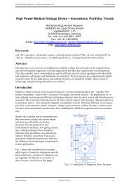
The IGCT is at the forefront of <strong>technology</strong> in high power, medium-voltage applications. For further<br />
improvement in size and costs a new ANPC IGCT <strong>PEBB</strong> has been developed. The main new technologies<br />
to achieve higher powers are the new low-inductive gate-unit to maintain hardswitched operation up to<br />
more than 6000A, the increased SOA of the 91mm asymmetric IGCT (4 inch <strong>technology</strong>) and the<br />
antiparallel diode up to more than 6000A and the Active NPC <strong>technology</strong>, which allows an optimum and<br />
equal loss balancing in all power semiconductors<br />
The maximum inverter output power has been increased by 80% with a parallel increase in the power<br />
density and reduced costs per kVA.<br />
EPE 2005 - Dresden ISBN : 90-75815-08-5 P.1
<strong>Very</strong> <strong>High</strong> <strong>Power</strong> <strong>PEBB</strong> <strong>technology</strong> BRUECKNER Thomas<br />
Introduction<br />
<strong>Power</strong> electronics is a <strong>technology</strong> of continuously growing importance in multiple areas like<br />
• power generation<br />
• transmission and distribution<br />
• multiple industrial applications and<br />
• transportation.<br />
Mature applications may be found in static excitation systems for power generation, HVDC<br />
transmission systems, rectifiers for DC loads, UPS products, adjustable speed drives and converters for<br />
rolling stock. Emerging applications for power electronics have been evolving in all the above areas, such<br />
as :<br />
• new voltage-source converter based HVDC transmission systems (HVDC light),<br />
• new FACTS solutions like the UPFC or SSSC for powerflow and STATCOM for voltage<br />
control,<br />
• new Custom <strong>Power</strong> products to protect critical loads, like dynamic voltage restorers (DVR),<br />
• new energy storage solutions based on flywheel <strong>technology</strong>, conventional and advanced<br />
batteries and<br />
• new distributed power generation solutions based on windturbines, microturbines and fuel cells.<br />
More and more <strong>PEBB</strong> based approaches to power electronics are chosen to exploit the synergies of<br />
multiple applications. In the field of power electronics the <strong>PEBB</strong> is a key functional component, which<br />
enables a platform-based approach.<br />
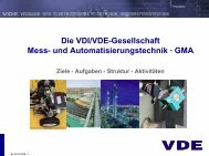
Definition of the <strong>Power</strong> Electronics Building Block (<strong>PEBB</strong>)<br />
The functionality of a <strong>PEBB</strong> [1], as a basic building block, can be defined as power conversion (single<br />
phase or multiple phases) including (Fig. 1)<br />
• power supply for gate drives and sensors<br />
• stack or module assembly including gate drives<br />
• voltage, current and temperature sensors incl. A/D conversion of sensor signals<br />
• switching control incl. pulse generation for gate drive<br />
• communication with control and<br />
• primary protection.<br />
The interfaces of a <strong>PEBB</strong> can be defined as follows:<br />
• auxiliary power interface<br />
• control interface<br />
• power interfaces and<br />
• cooling interface.<br />
With this proposed definition [2], the complexity of power electronics systems can be reduced due to<br />
basic building block and interface definition. The interface with the highest complexity is that between the<br />
<strong>PEBB</strong> and the control. This interface may also have a different definition and functionality depending on<br />
the degree of integration within the <strong>PEBB</strong>.<br />
To achieve a clearly defined, scalable and easy to implement interface between the control and the<br />
<strong>PEBB</strong> it is proposed that, in very high power applications, additional intelligence be included within the<br />
<strong>PEBB</strong>. This additional intelligence should be based, in a first step, on the level <strong>PEBB</strong> control (see Fig. 1),<br />
which includes the following functionality<br />
• modulator with switching logic and<br />
EPE 2005 - Dresden ISBN : 90-75815-08-5 P.2
<strong>Very</strong> <strong>High</strong> <strong>Power</strong> <strong>PEBB</strong> <strong>technology</strong> BRUECKNER Thomas<br />
• the 2 nd level of protection.<br />
This additional intelligence should be physically located close to the power part of the <strong>PEBB</strong> as<br />
distributed intelligence.<br />
A / D & D/A<br />
V DC1 T<br />
V<br />
PLL, αβ ↔ dq Transformations<br />
id / iq current control<br />
2nd 2 level<br />
protection<br />
nd level<br />
protection<br />
System control<br />
Application control<br />
Gate drives &<br />
device protection<br />
FB<br />
Modulator<br />
Converter<br />
switching logic<br />
6<br />
1..6<br />
A / D & D/A<br />
I A/B/C V A/B/C<br />
(optional)<br />
V<br />
Configuration<br />
& & diagnostics diagnostics<br />
Application Control<br />
- overriding control & measurements<br />
Converter Control<br />
- PLL synchronization<br />
- αβ ↔ dq Transformations<br />
- id- and iq current control<br />
<strong>PEBB</strong> Control<br />
- Modulator<br />
- Converter switching logic<br />
- 2nd - Modulator<br />
- Converter switching logic<br />
- 2 level protection<br />
nd level protection<br />
<strong>PEBB</strong><br />
- Stack or module assembly<br />
- Snubbers for safe commutation<br />
- Gate drives & feedbacks<br />
- 1st - Stack or module assembly<br />
- Snubbers for safe commutation<br />
- Gate drives & feedbacks<br />
- 1 level device protection<br />
- A/D & D/A conversion<br />
- Gate drive power supply<br />
- Current and voltage sensors<br />
- AC/DC power terminals<br />
- Thermal management<br />
st level device protection<br />
- A/D & D/A conversion<br />
- Gate drive power supply<br />
- Current and voltage sensors<br />
- AC/DC power terminals<br />
- Thermal management<br />
Fig. 1: <strong>PEBB</strong> and its possible levels of integration according to IEEE guide [3]<br />
1ms..1s..<br />
10 µs..1ms<br />
1..10 µs<br />
0.1..1 µs<br />
In a next step it is possible to include within the <strong>PEBB</strong> the next level, i.e. the Converter Control. This<br />
may happen first at lower powers. In such a solution the following additional functionalities would be<br />
integrated within the <strong>PEBB</strong>:<br />
• synchronization with the connected AC system<br />
• transformation of the variables in to rotating systems<br />
• current control within the rotating systems.<br />
It is important to understand that the definition of a <strong>PEBB</strong> allows a high level of flexibility and that<br />
<strong>PEBB</strong> definitions exist with highly different levels of integration. But in all cases the interfaces of the<br />
<strong>PEBB</strong> and its own functionality are clearly defined.<br />
<strong>PEBB</strong> Type 1 = <strong>PEBB</strong> <strong>Power</strong>part<br />
<strong>PEBB</strong> Type 2 = <strong>PEBB</strong> <strong>Power</strong>part +<br />
<strong>PEBB</strong> Control<br />
<strong>PEBB</strong> Type 3 = <strong>PEBB</strong> <strong>Power</strong>part +<br />
<strong>PEBB</strong> Control +<br />
Converter Control<br />
<strong>PEBB</strong> Type 4 = ….<br />
As mentioned before, for very high power applications, it is proposed to use the <strong>PEBB</strong> Type 2, i.e. the<br />
<strong>PEBB</strong> <strong>Power</strong>part with integrated <strong>PEBB</strong> Control functionality.<br />
EPE 2005 - Dresden ISBN : 90-75815-08-5 P.3
<strong>Very</strong> <strong>High</strong> <strong>Power</strong> <strong>PEBB</strong> <strong>technology</strong> BRUECKNER Thomas<br />
<strong>Power</strong> Semiconductor Technology<br />
Silicon based power semiconductors are an essential key component of the <strong>PEBB</strong>. It is therefore<br />
important, that the basic properties of the commonly used power semiconductors are understood.<br />
The low-voltage IGBT module<br />
The low-voltage IGBT module is used in low-voltage applications up to few megawatts with system<br />
voltages in the range of 240V up to 690V. With its typical dynamic blocking voltage in the range of 600V<br />
up to 1700V it is the dominant power semiconductor in these applications. The typical PWM carrier<br />
frequencies in the higher power range are in the range of a few kHz, typically 3 – 5 kHz. The dominant<br />
applications of the low-voltage IGBT module are low-voltage AC drives, where these power<br />
semiconductors are used in high volumes.<br />
Econopack /SKiiP/LoPak Module 1200 V und 1700 V<br />
Maximum blocking voltage<br />
Fig. 2: The low-voltage IGBT module<br />
The medium-voltage-IGBT module<br />
IHV / HiPak Module (E1/E2)<br />
Turn off 3x rating current (3300V IGBT)<br />
75 – 450 A<br />
Maximum phase current<br />
Switching frequency (f PWM)<br />
1200 V: Typical 3..5 kHz<br />
Integration<br />
Fig. 3: The medium-voltage IGBT module<br />
Electrical insulation<br />
Up to six switching devices<br />
Loss-optimized<br />
Soft Punch Through or<br />
Trench<br />
Copper base plate (EconoPack)<br />
Limited in thermal cycles<br />
2500 V, 3300 V and 6500 V<br />
Maximum blocking voltage<br />
1500 A, 1200 A, 600 A<br />
Maximum phase current<br />
Switching frequency (f PWM )<br />
3300 V: Typical 1..2 kHz<br />
Integration<br />
Electrical insulation<br />
Up to 2 devices (dual pack)<br />
Loss-optimized<br />
Soft Punch Through or<br />
Trench<br />
AlSiC base plate<br />
Traction<br />
The medium-voltage IGBT module with dynamic blocking voltages in the range of 2500 V to 6500V is<br />
used in medium-voltage applications up to a few megawatts. The typical PWM carrier frequencies in these<br />
high power applications are in the range of 1 to 2 kHz. The dominant application for this power<br />
semiconductor is traction propulsion.<br />
EPE 2005 - Dresden ISBN : 90-75815-08-5 P.4
<strong>Very</strong> <strong>High</strong> <strong>Power</strong> <strong>PEBB</strong> <strong>technology</strong> BRUECKNER Thomas<br />
The medium-voltage-IGCT Presspack<br />
The medium-voltage IGCT [4] is a presspack device with its typical dynamic blocking voltage in the<br />
range of 4500V to 6000V. It consists of one bipolar wafer only, which has structures like a GTO device. It<br />
can therefore be manufactured on more simple wafer fabs, which already achieve low production costs<br />
with lower production volumes owing to the substantially lower investment costs. Additionally the one<br />
wafer solution needs inherently less edge termination area, than comparable solutions based on multiple<br />
small wafers. The IGCT is used in medium-voltage applications up to 100 MW and higher. The typical<br />
PWM carrier frequencies in high power applications are in the range of as low as 50 Hz up to 1 kHz. The<br />
dominant application of the medium voltage IGCT are medium-voltage AC drives, where these power<br />
semiconductors are used in high volumes.<br />
Today, the IGCT is the power semiconductor, which is best established in all high power applications.<br />
It has the most impressive reference list and is employed in the highest number of installations.<br />
As a thyristor-based power semiconductor, the IGCT has very low on-state losses. Owing to its<br />
integrated gate drive the turn-off occurs in an inherently robust transistor mode. Additionally, the<br />
presspack housing has the necessary attribute, that it fails short and any plasma is contained within the<br />
power semiconductor housing. This feature allows the implementation of robust and reliable protection<br />
concepts, which are essential for very high power applications.<br />
4<br />
3<br />
2<br />
1<br />
0<br />
-10<br />
-20<br />
V g<br />
(V)<br />
IGCT Presspack<br />
V d<br />
(kV)<br />
I Itg tg<br />
q<br />
V dm<br />
anode current I a<br />
thyristor x<br />
transistor<br />
starts to block<br />
anode voltage V d<br />
gate voltage<br />
V g<br />
I a (kA)<br />
1.5 2.0 2.5 3.0 3.5 t (µ s)<br />
4<br />
1<br />
3<br />
2<br />
0<br />
4500 V and 6000 V<br />
Maximum blocking voltage<br />
150 – 2000 A<br />
Maximum phase current<br />
Switching frequency (f PWM )<br />
Typical 0.5 – 1 kHz<br />
Integration<br />
Gate unit<br />
Loss-optimized<br />
Transparent Anode<br />
Thyristor-based<br />
Presspack<br />
Short circuit<br />
di/dt – snubber<br />
Fig. 4.: The medium-voltage IGCT presspack<br />
The medium-voltage IGBT Presspack<br />
The medium-voltage IGBT presspack with a typical dynamic blocking voltage of 2500V up to 4500V is<br />
used mainly in high voltage DC transmission up to a few 100 MW. The typical PWM carrier frequencies<br />
are in the range of 0.5 – 2 kHz. The IGBT presspack consists of multiple IGBT wafers, each needing its<br />
own small presspack structure. The IGBT chips are manufactured on the newest generation of IGBT wafer<br />
fabs, which are able to process the much finer structure required for this type of power semiconductor.<br />
When considering a power semiconductor switching at elevated frequencies, i.e. above 3 to 5 times<br />
the fundamental frequency, the IGBT has the advantage that the gate drive needs a smaller power supply.<br />
This is particularly beneficial in higher voltage applications, as the energy extraction on potential is<br />
simpler. This is one of the main reasons, that the IGBT presspack <strong>technology</strong> has been introduced in high<br />
voltage DC transmission systems, i.e. HVDC light based on voltage source converter <strong>technology</strong>.<br />
EPE 2005 - Dresden ISBN : 90-75815-08-5 P.5
<strong>Very</strong> <strong>High</strong> <strong>Power</strong> <strong>PEBB</strong> <strong>technology</strong> BRUECKNER Thomas<br />
IGBT Presspack<br />
2500 V and 4500 V<br />
Maximum blocking voltage<br />
600 – 2000 A<br />
Maximum phase current<br />
Switching frequency (f PWM )<br />
2500 V: typical 1 – 2 kHz<br />
4500 V: typical 0.5 – 1 kHz<br />
Integration<br />
Single device<br />
Loss-optimized<br />
Soft Punch Through or<br />
Trench<br />
Presspack<br />
Fig. 5.: The medium-voltage IGBT presspack<br />
Comparison of power semiconductors<br />
Short circuit<br />
In Fig. 6 a comparison of the features of the most important power semiconductors and their applications<br />
is made:<br />
• in the lower MW range the low-voltage IGBT module is the dominant design, combining low<br />
costs and high efficiency.<br />
• in the higher MW range, MV <strong>technology</strong> is used and the medium-voltage IGCT presspack is the<br />
dominant design up to several 100 MW owing to the benefits it provides with regard to :<br />
o Lower cabling efforts due to lower currents<br />
o Lower complexity due to lower parts count<br />
o <strong>High</strong>er efficiency as the IGCT is derived from the lowest loss thyristor <strong>technology</strong><br />
o Achieving a robust and reliable protection concept due to the presspack <strong>technology</strong>.<br />
• In high voltage DC transmission systems based on voltage source <strong>technology</strong> (HVDC light) the<br />
medium-voltage IGBT presspack <strong>technology</strong>, adapted to fulfill very specific HVDC<br />
requirements, has found its market niche.<br />
Application<br />
Cost<br />
IGBT Module<br />
Low- and<br />
medium-voltage<br />
Low<br />
IGCT Presspack<br />
Medium voltage<br />
(up to 15 kV)<br />
<strong>Power</strong> 1 – 5 MW<br />
5 – 100 MW<br />
Losses Medium<br />
Low<br />
Low<br />
IGBT Presspack<br />
Medium and HV<br />
(up to +/- 150kV)<br />
Scalability<br />
Parallel & Series<br />
Parallel<br />
Parallel & Series<br />
(with snubber)<br />
Type of failure Open (Plasma) Short circuit<br />
50 – 300 MW<br />
Medium<br />
Medium<br />
Short circuit<br />
LV Drives MV Drives HVDC light<br />
Traction FACTS FACTS<br />
<strong>Power</strong> Quality <strong>Power</strong> Quality<br />
Fig. 6: Comparison of the most important power semiconductors and their applications<br />
With regard to the applications, it is of the outmost importance that the <strong>PEBB</strong> <strong>technology</strong> used is<br />
compact, cost-effective, reliable and highly efficient. When focusing on the higher MW range up to more<br />
100 MVA the medium-voltage IGCT presspack <strong>technology</strong> is the prime choice, as it offers the lowest<br />
costs and the highest efficiency. Regarding series and parallel connection, the trade-offs are minor as only<br />
small snubbers, if any, are needed to overcome these limitations.<br />
EPE 2005 - Dresden ISBN : 90-75815-08-5 P.6
<strong>Very</strong> <strong>High</strong> <strong>Power</strong> <strong>PEBB</strong> <strong>technology</strong> BRUECKNER Thomas<br />
NPC IGCT <strong>PEBB</strong> Technology<br />
The NPC IGCT <strong>PEBB</strong><br />
Based on the highly competitive IGCT <strong>technology</strong> a very compact NPC IGCT <strong>PEBB</strong>, called <strong>Power</strong>Stack<br />
(Fig. 7.), serving multiple medium-voltage applications has been introduced to the market and the first<br />
commercial installations were commissioned in the year 2000.<br />
Fig. 7: NPC IGCT <strong>PEBB</strong> – a leading edge <strong>PEBB</strong> based on medium-voltage IGCT presspack <strong>technology</strong><br />
Cd1<br />
Cd2<br />
Ls1<br />
Rcl1<br />
Rcl2<br />
Ls2<br />
Ccl1<br />
Ccl2<br />
NPC IGCT <strong>PEBB</strong><br />
Dcl1<br />
Dcl2<br />
D5<br />
D6<br />
Fig 8: NPC IGCT <strong>PEBB</strong> Topology<br />
S1<br />
S2<br />
S3<br />
S4<br />
D1<br />
D2<br />
D3<br />
D4<br />
The maximum output power of the water-cooled NPC IGCT <strong>PEBB</strong> in a 3-phase configuration is in the<br />
range of 9 MVA. The NPC IGCT <strong>PEBB</strong> is a highly compact, highly reliable and efficient medium-voltage<br />
design, which defines the basic metrics for any competitive solution in this field. The system voltage with<br />
the 4500 V or 6000 V IGCTs is limited to 3300 V or 4160V correspondingly.<br />
Applications of the NPC IGCT <strong>PEBB</strong>)<br />
The NPC IGCT <strong>PEBB</strong> has been successfully introduced into the market to serve multiple, highly<br />
demanding, mature and emerging applications like<br />
• 9 – 27 MVA medium-voltage drives for various applications including rolling mills and marine<br />
propulsion,<br />
• 15 MVA back-to-back inter-tie to connect the 50 Hz grid and the 162/3Hz grid of European<br />
traction systems,<br />
• 15 – 60 MVA energy storage systems based on regenerative fuel cell <strong>technology</strong> or NiCd<br />
EPE 2005 - Dresden ISBN : 90-75815-08-5 P.7
<strong>Very</strong> <strong>High</strong> <strong>Power</strong> <strong>PEBB</strong> <strong>technology</strong> BRUECKNER Thomas<br />
battery <strong>technology</strong> to enhance grid stability or to reduce power fluctuations.<br />
• 22 MVA Dynamic Voltage Restorers to safeguard the highly critical processes of a<br />
semiconductor plant.<br />
Fig. 9: Back-to-back intertie based on the NPC IGCT <strong>PEBB</strong><br />
The New ANPC IGCT <strong>PEBB</strong><br />
Limitations of the NPC IGCT <strong>PEBB</strong><br />
The maximum output power of the NPC IGCT <strong>PEBB</strong> is limited mainly by two factors, i.e.<br />
• the safe operation area of the IGCT and<br />
• the thermal management of the power semicon-ductors.<br />
The maximum power of the conventional NPC IGCT <strong>PEBB</strong> is limited by the maximum turn-off<br />
capability of the IGCT and the corresponding companion diode. The maximum turn-off capability linked<br />
to the 4 inch wafer <strong>technology</strong> is in the range of 4000A at a DC voltage of 2800 Vdc.<br />
At the same time, in a conventional NPC converter with diodes clamped to the neutral point, the loading<br />
of the outer and the inner IGCT and corresponding antiparallel diodes is different, for example, at<br />
• a power factor equal to one<br />
• a high modulation and<br />
• delivering active power from DC to AC<br />
the outer IGCTs (S1, S4) of the NPC IGCT <strong>PEBB</strong> have reached their thermal limit, i.e. the thermal<br />
resistance of the IGCT and the water cooling circuit will not allow any higher losses. On the other side the<br />
inner IGCTs (S2, S3) are thermally loaded much less, as their losses are caused by conduction losses only.<br />
In case of inverse energy direction the same happens with the corresponding antiparallel diodes.<br />
The new technologies introduced with the ANPC IGCT <strong>PEBB</strong><br />
To further improve the power density and the cost competitiveness of the leading IGCT <strong>PEBB</strong> <strong>technology</strong><br />
the ANPC IGCT <strong>PEBB</strong> has been developed, which is able to deliver up to 16 MVA output power. The<br />
main new technologies introduced to achieve higher output powers are:<br />
• increased SOA of the 91mm asymmetric IGCT (4 inch <strong>technology</strong>) and of the antiparallel diode<br />
up to more than 6000A [5] and<br />
• improved thermal management by means of the Active NPC topology [6].<br />
EPE 2005 - Dresden ISBN : 90-75815-08-5 P.8
<strong>Very</strong> <strong>High</strong> <strong>Power</strong> <strong>PEBB</strong> <strong>technology</strong> BRUECKNER Thomas<br />
The low-inductive gate unit<br />
To keep the IGCT in the hard-switched mode during turn-off, the gate current rise time needs to meet the<br />
following requirements. Typically the maximum turn-off current needs to be achieved in less than 1us,<br />
with a gate unit voltage of approximately –20V. By utilizing newest technologies of FET and capacitors in<br />
the turn-off channel combined with an optimum PCB layout, values of more than 7-8 kA / µs can be<br />
achieved with the result that currents of up to 6000A and more can be turned-off safely. <strong>High</strong>er values<br />
maybe possible, but the limit of the homogenous IGCT turn-off and the GTO type turn-off, with the risk<br />
of hot spots, needs to be carefully addressed.<br />
Fig. 10: Low-inductive 6000A IGCT gate unit<br />
New IGCT with increased SOA<br />
To achieve the needed higher turn-off current the IGCT <strong>technology</strong> has been further developed [5]. The<br />
development focused on<br />
• local improvement of the SOA, focusing on the IGCT cell level by optimizing the doping profiles<br />
and the irradiation. Record turn-off capabilities of 1 MW/ cm 2 have been achieved and<br />
• the reduction of lateral effects by optimizing the current distribution over the whole wafer area.<br />
Fig 11: 6.5 kA turn-off versus 2.8kVdc at 125°C with a 91mm asymmetric IGCT (4 inch <strong>technology</strong>).<br />
EPE 2005 - Dresden ISBN : 90-75815-08-5 P.9
<strong>Very</strong> <strong>High</strong> <strong>Power</strong> <strong>PEBB</strong> <strong>technology</strong> BRUECKNER Thomas<br />
Overall, a substantial improvement could be achieved, whereas the lateral effect and low temperature<br />
operations remain the main limitations with regard to SOA. As shown in Fig. 11, including the lateral<br />
effects, the turn-off capability could be kept above 450 kVA /cm 2 at 125°C with a reduction down to 350<br />
kVA /cm 2 at 25°C. It is expected that, in the near future, this performance can be further improved based<br />
on the knowledge gained in establishing this new high power IGCT generation.<br />
New ANPC (Active NPC) topology<br />
Using power semiconductors with improved turn-off capability would not improve the output power<br />
substantially as the limitations set by the thermal management of the NPC topology cannot be overcome.<br />
By combining it with the advanced Active NPC topology the output power can be increased to 16 MVA.<br />
The Active NPC topology makes it possible to balance the semiconductor losses in the relevant IGCTs<br />
and diodes, thus differentiating this topology from the well-known NPC topology [6], for example at<br />
• a power factor equal to one<br />
• a high modulation and<br />
• delivering active power from DC to AC<br />
the thermal loading of pairs of outer and inner IGCTs (S1/S2 and S3/S4) of the ANPC IGCT <strong>PEBB</strong> can be<br />
equalized by distributing the turn-off switching actions needed to connect the outer potentials to the<br />
neutral potential. In case of inverse energy direction the same can be done to load the corresponding<br />
antiparallel diodes equally.<br />
Cd1<br />
Cd2<br />
Ls1<br />
Rcl1<br />
Rcl2<br />
Ls2<br />
ANPC IGCT <strong>PEBB</strong><br />
Ccl1<br />
Ccl2<br />
Dcl1<br />
Dcl2<br />
Fig. 12: Active NPC IGCT <strong>PEBB</strong> Topology<br />
The ANPC IGCT <strong>PEBB</strong><br />
S5<br />
S6<br />
D5<br />
D6<br />
S1<br />
S2<br />
S3<br />
S4<br />
D1<br />
D2<br />
D3<br />
D4<br />
Based on these basic innovations the ANPC IGCT <strong>PEBB</strong> has been developed. The mechanical<br />
arrangement is shown in Fig. 13. Overall the following improvements have been obtained:<br />
NPC IGCT ANPC IGCT<br />
<strong>PEBB</strong><br />
<strong>PEBB</strong><br />
Output power 100 % 180%<br />
<strong>Power</strong> density<br />
on stack level<br />
100 % 130 %<br />
<strong>Power</strong> density<br />
on inverter<br />
level<br />
100 % 150% on average<br />
EPE 2005 - Dresden ISBN : 90-75815-08-5 P.10
<strong>Very</strong> <strong>High</strong> <strong>Power</strong> <strong>PEBB</strong> <strong>technology</strong> BRUECKNER Thomas<br />
Fig. 13: The ANPC IGCT <strong>PEBB</strong> (16 MVA <strong>Power</strong>Stack)<br />
Conclusions<br />
The IGCT is the leading <strong>technology</strong> in high power, medium voltage applications. The <strong>technology</strong> has been<br />
further developed and the maximum inverter output power without series connection has been increased<br />
by 80% with a parallel increase in the power density.<br />
Applying IGCT <strong>technology</strong> in the building of high power <strong>PEBB</strong>s makes it possible to deploy<br />
synergies of leading-edge <strong>PEBB</strong> designs over multiple applications due to defined interfaces and a<br />
platform-based based approach to power electronics systems.<br />
References<br />
[1] T. Ericsen, “<strong>Power</strong> Electronics Building Blocks”, The Electric Warship Conference, IME/IEE/SEE, London,<br />
1997<br />
[2] P. Steimer, “<strong>Power</strong> Electronics Building Blocks - a Platform-based Approach to <strong>Power</strong> Electronics”, IEEE<br />
<strong>Power</strong> Engineering Society, Toronto, 2003<br />
[3] IEEE <strong>Power</strong> Engineering Society, “<strong>Power</strong> Electronics Building Block (<strong>PEBB</strong>) Concepts”, IEEE Guide - Task<br />
Force 2 Wgi8 Document, Product Number 04TP170, 2004, contact: customer-service@ieee.org<br />
[4] P. Steimer, H.E. Grüning, J. Werninger, E. Carroll, S. Klaka, and S. Linder, “IGCT – A new emerging<br />
<strong>technology</strong> for high power low cost inverters,” in Conf. Rec. IEEE-IAS Annual Meeting, 1997, pp. 1592–1599.<br />
[5] T. Stiasny, P. Streit, M. Lüscher, M. Frecker, “Large area IGCTs with improved SOA“, Nuremberg, PCIM<br />
2004.<br />
[6] T. Brückner, S. Bernet, "Loss balancing in three-level voltage source inverters applying active NPC switches,"<br />
in Proc. IEEE-PESC, Vancouver, Canada, 2001, pp. 1135-1140<br />
EPE 2005 - Dresden ISBN : 90-75815-08-5 P.11