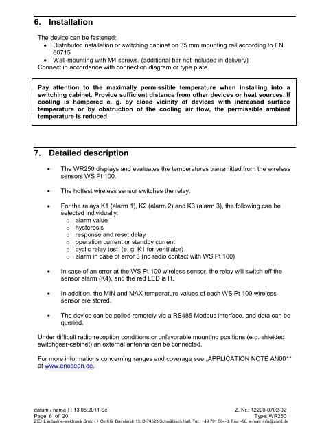
Operating instructions Wireless temperature relay type WR250
Operating instructions Wireless temperature relay type WR250
Operating instructions Wireless temperature relay type WR250
You also want an ePaper? Increase the reach of your titles
YUMPU automatically turns print PDFs into web optimized ePapers that Google loves.
6. Installation<br />
The device can be fastened:<br />
Distributor installation or switching cabinet on 35 mm mounting rail according to EN<br />
60715<br />
Wall-mounting with M4 screws. (additional bar not included in delivery)<br />
Connect in accordance with connection diagram or <strong>type</strong> plate.<br />
Pay attention to the maximally permissible <strong>temperature</strong> when installing into a<br />
switching cabinet. Provide sufficient distance from other devices or heat sources. If<br />
cooling is hampered e. g. by close vicinity of devices with increased surface<br />
<strong>temperature</strong> or by obstruction of the cooling air flow, the permissible ambient<br />
<strong>temperature</strong> is reduced.<br />
7. Detailed description<br />
The <strong>WR250</strong> displays and evaluates the <strong>temperature</strong>s transmitted from the wireless<br />
sensors WS Pt 100.<br />
The hottest wireless sensor switches the <strong>relay</strong>.<br />
For the <strong>relay</strong>s K1 (alarm 1), K2 (alarm 2) and K3 (alarm 3), the following can be<br />
selected individually:<br />
o alarm value<br />
o hysteresis<br />
o response and reset delay<br />
o operation current or standby current<br />
o cyclic <strong>relay</strong> test (e. g. K1 for ventilator)<br />
o alarm in case of error 3 (no radio contact with WS Pt 100)<br />
In case of an error at the WS Pt 100 wireless sensor, the <strong>relay</strong> will switch off the<br />
sensor alarm (K4), and the red LED is lit.<br />
In addition, the MIN and MAX <strong>temperature</strong> values of each WS Pt 100 wireless<br />
sensor are stored.<br />
The device can be polled remotely via a RS485 Modbus interface, and data can be<br />
queried.<br />
Under difficult radio reception conditions or unfavorable mounting positions (e.g. shielded<br />
switchgear-cabinet) an external antenna can be connected.<br />
For more informations concerning ranges and coverage see „APPLICATION NOTE AN001“<br />
at www.enocean.de.<br />
datum / name ) : 13.05.2011 Sc Z. Nr.: 12200-0702-02<br />
Page 6 of 20 Type: <strong>WR250</strong><br />
ZIEHL industrie-elektronik GmbH + Co KG, Daimlerstr.13, D-74523 Schwäbisch Hall, Tel.: +49 791 504-0, Fax: -56, e-mail: info@ziehl.de


