HZ-lock documentation (PDF) - Glutz
HZ-lock documentation (PDF) - Glutz
HZ-lock documentation (PDF) - Glutz

Create successful ePaper yourself
Turn your PDF publications into a flip-book with our unique Google optimized e-Paper software.
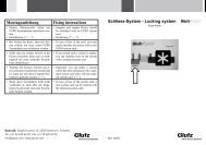
<strong>HZ</strong>-<strong>lock</strong> Documentation
Index of contents<br />
Functional description 4<br />
Advantages at a glance 5<br />
User instructions and maintenance recommendations 6<br />
Installation instructions I 7<br />
Installation instructions II 8 - 9<br />
Reversing the panic function 10<br />
Removing the panic function bolt 11<br />
<strong>HZ</strong>-<strong>lock</strong> with additional latch 11<br />
Control of electrical feedback 12<br />
Option: Electrical <strong>lock</strong> operation b<strong>lock</strong> 13<br />
Wiring diagram 14 - 15<br />
Faults – causes – remedies 16 - 17
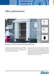
4<br />
The multifunctional security door <strong>lock</strong><br />
Functional description<br />
The <strong>HZ</strong>-<strong>lock</strong> multi-<strong>lock</strong>ing system for burglar-resistant leaf doors fulfils all desired functions and<br />
requirements. When the door closer moves the door to the closed position, it is first the <strong>lock</strong> latch that<br />
engages in the opening in the strike plate and positions the door in the <strong>lock</strong>ing position; then the three bolts<br />
(normally 1 bolt each at the bottom, middle and top of the door) are automatically extended by 20 mm (self<strong>lock</strong>ing).<br />
In the extended position the bolts are <strong>lock</strong>ed in the <strong>lock</strong> box to prevent them from being pushed<br />
back. The <strong>lock</strong> box is made of hardened metal, making it difficult to drill open.<br />
In the basic position, the door lever on the outside is not engaged. Normally, the door lever engages in<br />
the <strong>lock</strong> mechanism when it is activated by the solenoid magnet, which in turn is controlled by the access<br />
control system. As long as the magnet is live, the lever engages in the mechanism and will retract the <strong>lock</strong><br />
latch and bolts when it is operated. The bolts remain in their fully retracted positions, even if they do not<br />
have to be fully retracted because of a wide gap between door and frame. In the case of a power cut or when<br />
the door needs to be opened by the rescue service in an emergency, the door lever can also be engaged with<br />
the appropriate safety key via the safety cylinder.<br />
The internal door lever is always permanently connected to the <strong>lock</strong> mechanism. Therefore, the door<br />
can always be opened from the inside using a single continuous hand movement on the door lever, thus<br />
complying with the requirements of an emergency exit <strong>lock</strong>. Where exit control is also required, an<br />
independent additional latch is fitted to the <strong>lock</strong> mechanism and the door is equipped with an escape door<br />
opener and escape route controls.<br />
The <strong>lock</strong> system has passed the required tests under DIN 18251 Class IV carried out at the Material Testing<br />
Office in Dortmund and therefore complies with the requirements for a <strong>lock</strong> for enhanced burglar resistance<br />
and high user frequency. In addition, the system has the benefit of verification of suitability for installation<br />
in fire safety and smoke protection doors, as well as the test certificate for use as emergency exit <strong>lock</strong> in<br />
accordance with EN 179 in combination with <strong>Glutz</strong> fire protection fittings. All commercially available<br />
safety cylinders can be used with <strong>HZ</strong>-<strong>lock</strong>.
Advantages at a glance<br />
1. Multifunctionality<br />
• Burglar resistance up to Resistance Class WK 4 / RC4<br />
• Automatic self-<strong>lock</strong>ing<br />
• Suitable for all access control systems (also possible with exit control)<br />
• Emergency exit <strong>lock</strong> tested to EN 179<br />
• Suitable for doors on escape routes<br />
• Certified suitability for fire safety and smoke control doors<br />
• For all commonly available standard safety cylinders with any cylinder cam position<br />
• Can be reversed inwards / outwards without opening the <strong>lock</strong> box<br />
2. Reliability<br />
• Tested to DIN 18251 Class 4 (3 doors with 500,000 operating cycles each)<br />
• The bolts do not extend automatically until the door is in fully closed position<br />
• If the lever is not fully depressed when opening the door, the bolts remain in their respective retracted<br />
position and the door will <strong>lock</strong> again automatically<br />
• Strong continuous forend increases the strength and durability of the door and its shape<br />
• Deformation of the door is prevented by continuous three-point <strong>lock</strong>ing<br />
3. Burglar protection<br />
• Door elements have been tested for suitability up to Class WK 4<br />
• Three <strong>lock</strong>ing bolts with 20 mm protrusion<br />
• Lock housing in hardened steel (resistant to drilling)<br />
• Bolts in hardened steel<br />
• Additional bolts fitted with hardened connection rods<br />
• Connection rods in the forend with back cover made of spring steel<br />
• Ready for installation of commonly available safety cylinders and protection fittings<br />
4. Installation<br />
• Modular system<br />
• The complete <strong>lock</strong> is inserted from the forend at the front<br />
• Integrated cylinder fixing<br />
• Single supply cable to the door for all control and monitoring contacts<br />
5. Control and monitoring<br />
• Depending on the voltage, the coupling magnet can be replaced without opening the <strong>lock</strong> box<br />
• “Lever disengaged” diode and polarisation protection diode for coupling magnet permanently installed<br />
• Reliable door monitoring by serial connection of a door position and a bolt position contact<br />
• Door lever contacts for suppressing a break-in alarm when the door is opened using the anti-panic<br />
function (without exit control)<br />
• Potential free switch contact when the external lever is engaged using the key, for example for un<strong>lock</strong>ing<br />
the electric bolts on escape routes<br />
• If required, the electric control of the magnet can be switched off via the safety cylinder (b<strong>lock</strong> cylinder)<br />
• Highly flexible flex cable with push-fit connection to the <strong>lock</strong> included<br />
5
6<br />
User instructions and maintenance recommendations<br />
1. Entry<br />
In the “<strong>lock</strong>ed” base position, the external door lever is detached from the <strong>lock</strong> mechanism and does not<br />
engage when it is moved. When the access control system connects the power supply to the electromagnet<br />
in the <strong>lock</strong>, the external door lever engages with the <strong>lock</strong> mechanism. When the lever is operated during<br />
that phase it will retract the bolt and latch simultaneously. If the lever is not operated, the power supply will<br />
again be disconnected and the lever disengages again automatically.<br />
In the case of a power cut, a fault in the electric controls or for emergency opening by the rescue service, it<br />
is possible to open the door purely mechanically with the appropriate cylinder key. To do this, turn the key<br />
in the security cylinder in the opening direction until it stops, hold the key in this position and then, at the<br />
same time, operate the door lever.<br />
2. Exit<br />
All <strong>lock</strong>s marked “panic” on the forend always have the internal door lever fixed connected with the <strong>lock</strong><br />
mechanism. Operating this internal door lever will always open the exit. In special cases it is also possible for<br />
a green emergency button to be installed near the door; in this case the emergency button has to be operated<br />
before the exit is released for opening; this usually triggers an alarm.<br />
3. Locking<br />
The <strong>lock</strong> automatically <strong>lock</strong>s the door with three bolts after each <strong>lock</strong>ing action. It is therefore not necessary<br />
to turn the key in the cylinder. However, it is necessary for the bolts and latch to be able to enter the respective<br />
openings in the strike plate or in the frame without obstruction so that the automatic <strong>lock</strong>ing mechanism<br />
can work properly. A door position contact and a bolt position contact are fitted in the electrical <strong>lock</strong>. These<br />
make it possible to monitor correct <strong>lock</strong>ing – something that is highly recommended.<br />
4. Maintenance<br />
The following regular maintenance checks are recommended at intervals of not more than one month; these<br />
are to be carried out by the operating organisation or a third party.<br />
a) Cleaning with cleaning agents that do not contain corrosive substances.<br />
b) Inspection and functional check of emergency exit <strong>lock</strong> in order to ensure that all parts of the <strong>lock</strong>ing<br />
mechanism are functional and in a satisfactory operating condition.<br />
c) Ensuring that the openings opposite the <strong>lock</strong>ing devices are not b<strong>lock</strong>ed.<br />
d) The <strong>lock</strong> latch, the control latch and the bolts have to be lubricated at least twice annually – more often<br />
depending on usage – without opening the <strong>lock</strong> box, using a little grease (no spray). It is not permitted to<br />
spray substances into the inside of the <strong>lock</strong>. The door closes more easily and without noise if the sloping<br />
surface of the latch is always lightly greased (the security cylinder has to be removed before it can be<br />
sprayed for maintenance purposes).<br />
e) Checking that no additional <strong>lock</strong>ing devices have been installed since the first installation of the door.<br />
f ) A check should be carried out annually that all components of the system are in accordance with the list<br />
of approved components originally supplied with the system.<br />
g) With heavy use of the door, a revision of the door <strong>lock</strong> is indicated after 2 to 3 years in order to ensure<br />
that the system functions reliably at all times. We can supply replacement <strong>lock</strong>s where required.
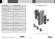
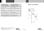
Installation instructions I<br />
Important:<br />
Please read the installation instructions carefully and carry out the installation carefully and accurately in<br />
order to ensure proper function of the system!<br />
IMPORTANT:<br />
• Assemble the forend carefully!<br />
• Do not bend the connection rods when inserting them into the main <strong>lock</strong> (will engage automatically)<br />
To release the forend extension insert the pin, apply light pressure and carefully pull apart without bending<br />
any parts.<br />
Latch bolt<br />
Control latch<br />
Bolt<br />
Cylinder fixing<br />
(use 3mm Allen key)<br />
Lever follower<br />
Cylinder cut-out<br />
Electric connection<br />
7
8<br />
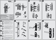
Installation instructions II<br />
Preliminary notes<br />
• For these products to comply with EN 179, their safety features are essential. No modifications are<br />
permitted except those described in these instructions.<br />
• <strong>HZ</strong>-<strong>lock</strong> is suitable for door elements up to 200 kg and for burglar-resistant door elements up to WK4.<br />
• <strong>HZ</strong>-<strong>lock</strong> with panic function: ensure that your burglar-resistant door construction provides resistance<br />
against impact and possible drilling when exposed to risk so that no large enough opening can be made<br />
to reach through, and that the door closes against a threshold at the bottom.<br />
1. Preparing the door<br />
• Cut the mortices for the <strong>lock</strong> in accordance with the drawing; provide lateral support for the <strong>lock</strong> box if<br />
appropriate; where specified, recess the forend to a depth of 6 mm.<br />
• Clean all mortices and profile tubes. Remove any sand!<br />
• The gap between the <strong>lock</strong> forend and the strike plate must be between 3 and 6 mm; drill the holes for the<br />
lever spindle and safety cylinder.<br />
2. Frame recesses<br />
The door is only positioned by the <strong>lock</strong> latch. The bolts must be able to engage in the strike plate openings<br />
without obstruction (at least 1 mm clearance on both sides, bolt protrusion = 20 mm). The control latch<br />
must not enter into an opening but must touch the frame or strike plate when it protrudes.<br />
3. Fitting the <strong>lock</strong><br />
Cut the forend at the top and, if required, at the bottom, to the exact length required.<br />
Allow the bolts at the main <strong>lock</strong> to extend by holding the <strong>lock</strong> latch pushed in and, at the same time, retaining<br />
the control latch below. When releasing the <strong>lock</strong> latch, the bolts extend.<br />
In order to connect the lower part of the <strong>lock</strong> and the upper forend extension, carefully insert the two<br />
connection rods of the forend extension into the guide grooves at the forend of the main <strong>lock</strong> until they<br />
engage automatically; proceed to place the Ω cut-outs of the forend profiles into each other.<br />
We recommend that you first fix the top forend extension loosely to the door with the top screw, then<br />
connect the main <strong>lock</strong> from below to the forend extension; let the connection rods engage and insert the<br />
<strong>lock</strong> in the prepared mortice recesses. It is imperative that the connection rods are not bent in the forend at<br />
the connecting point when assembling the lower part of the <strong>lock</strong> and the upper forend extension, as the <strong>lock</strong><br />
will not function with bent connection rods. No guarantee will be upheld where the connection rods are<br />
bent.<br />
Insert the plug – do not retract the cable on the hinge side – tighten the screws.<br />
Should it be necessary to disengage the upper forend extension, extend the bolts and push a pin (approx. 3<br />
mm) into the hole in the forend above the <strong>lock</strong> latch and simultaneously carefully pull the two parts apart.<br />
4. Fitting the cylinder<br />
Depending on the cut-out in the <strong>lock</strong> box, any profile cylinder to DIN 18252, or round Kaba/Keso<br />
cylinder, can be fitted. The <strong>lock</strong>ing bit can be in any position. The breakthrough for the safety cylinder in<br />
the door leaf must be sufficiently large. No part of the cylinder must make contact with the door leaf. To fix<br />
the cylinder, insert an Allen key (3 mm) into the hole in the forend underneath the bolt, approx. 60 mm<br />
deep into the fitted forend screw and use it to tighten the screw. Make sure that the cylinder is correctly<br />
centred in the <strong>lock</strong> and that the cylinder cam can function properly. Never operate the door lever or cause<br />
the bolts to extend while the Allen key is still in place.<br />
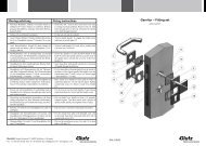
5. Fitting the protection fitting<br />
<strong>HZ</strong>-<strong>lock</strong> has been tested in combination with <strong>Glutz</strong> protection fittings ES-2 and ES-3 for compliance with<br />
EN 179. It is important that both door levers are fitted to the plates so that they can turn freely but are firm<br />
and stable (. The split lever pin does not hold the set in place and is not capable of withstanding tensile<br />
stress. When using roses, the stress on the follower parts would be too great. In this case we do not give<br />
any warranty for the <strong>lock</strong> system.
For drilling the holes it is preferable that you use the drilling template from the manufacturer of the<br />
protection fitting; this should be positioned at the follower of the lever and at the cylinder cut-out. Start<br />
drilling on both sides, remove the <strong>lock</strong>, drill the door leaf fully on both sides making sure not to damage the<br />
electrical supply cable! Clean the <strong>lock</strong> mortices and refit the <strong>lock</strong>.<br />
Prepare the screws to the correct length. When tightening the screws it is important that neither the lever<br />
spindle nor the cylinder in the <strong>lock</strong> get jammed. The door leaf must not be contracted; where necessary<br />
spacing sleeves must be provided.<br />
6. User instructions and maintenance recommendations<br />
The building owner/user must be instructed about the functions of the unit and the handing over of the<br />
enclosed instructions with maintenance recommendations must be confirmed in writing.<br />
The attached sticky note advising about opening the door with the key must be attached to the outside of<br />
the door until the above user instruction has been carried out.<br />
9
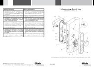
10<br />
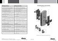
Reversing the panic function<br />
from the hinge side to the opposite side, and vice versa<br />
Tools required:<br />
1 door lever spindle, 9 x 9 mm<br />
1 Allen key, 1.5 mm<br />
1 half or double safety cylinder with key<br />
(<strong>HZ</strong>-<strong>lock</strong>: changing from disengaged position to panic function from point 7 needs<br />
an M2 x 5 mm Allen bolt)<br />
Procedure:<br />
1. Clamp the lower part of the <strong>lock</strong> to the workbench with the panic function facing<br />
upwards.<br />
2. Remove the round sticker with the <strong>HZ</strong> logo next to the lever follower; this will<br />
reveal a round opening in the <strong>lock</strong> box.<br />
3. Use the door lever with 9 x 9 mm spindle to operate the follower on the panic side<br />
until the bolt head with the hexagonal socket appears in the <strong>lock</strong> box opening;<br />
hold the follower in this position.<br />
4. Use the 1.5 mm Allen key to release and remove the bolt. Make sure that the<br />
follower stays still until the bolt has been removed so that it does not fall into the<br />
<strong>lock</strong> housing.<br />
5. The door lever can now be released.<br />
6. Turn the <strong>lock</strong> over (disengaged lever follower is now uppermost).<br />
7. Remove the round sticker with the <strong>HZ</strong> logo next to the follower; this will reveal a round opening in the<br />
<strong>lock</strong> box.<br />
8. Insert the safety cylinder, turn the key in the opening direction until it stops and hold in this position.<br />
9. Operate the follower simultaneously with the door lever until the threaded hole appears in the opening<br />
of the <strong>lock</strong> box; hold in this position.<br />
10. Carefully insert the cylinder head bolt previously removed and tighten normally (do not use excessive<br />
force!). Make sure that the follower stays still and that the bolt does not fall into the <strong>lock</strong> housing.<br />
11. Re-attach the two stickers to close the openings against any dust ingress.<br />
In our production we test each individual <strong>lock</strong> with a PC control system to ensure its proper function. The<br />
serial number includes a code of the function tested. If the sticker is damaged and subsequent modification<br />
has been carried out, we are unable to uphold our guarantee.<br />
In case of doubt, please contact the manufacturer in the first instance. An explanatory telephone conversation<br />
is normally cheaper than the cost of repairing a <strong>lock</strong>.
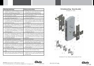
Removing the panic function bolt<br />
Tools required:<br />
1 door lever spindle, 9 x 9 mm<br />
1 Allen key, 1.5 mm<br />
Procedure:<br />
1. Clamp the lower part of the <strong>lock</strong> to the workbench with the panic function side<br />
uppermost.<br />
2. Remove the round sticker with the <strong>HZ</strong> logo on the forend side of the lever<br />
follower; this will reveal a round opening in the <strong>lock</strong> box.<br />
3. Use the 9 x 9 mm spindle to insert the door lever into the follower.<br />
4. Operate the follower with the door lever until a small cylinder head bolt with<br />
hexagonal socket appears in the <strong>lock</strong> box opening; hold the follower in this<br />
position.<br />
5. Carefully release and remove the cylinder head bolt using the 1.5 mm Allen key.<br />
Make sure that the follower stays still and that the bolt does not fall into the <strong>lock</strong><br />
housing.<br />
6. Re-attach the sticker to close the opening against any dust ingress.<br />
In our production we test each individual <strong>lock</strong> with a PC control system to ensure<br />
its proper function. The serial number includes a code of the function tested. If the<br />
sticker is damaged and subsequent modification has been carried out, we are unable<br />
to uphold our guarantee.<br />
In case of doubt, please contact the manufacturer in the first instance. An explanatory telephone conversation<br />
is normally cheaper than the cost of repairing a <strong>lock</strong>.<br />
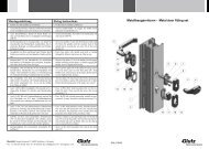
Control of electrical feedback<br />
The correct functioning of the door monitoring system (bolt position contact and door position contact)<br />
depends on:<br />
• All three bolts being fully extended.<br />
• The permanent magnet being correctly positioned in the frame (correct dimension under the lever axis,<br />
depending on the magnet fitted).<br />
• The distance between magnet and forend not being more than 5 mm.<br />
• The fitted magnet not being in contact with the steel components of the strike plate or frame.<br />
Checking<br />
1. With the door open: push in the main latch, retain the control latch, let go of the main latch, the bolts<br />
extend<br />
2. Hold the permanent magnet at a distance of max. 5 mm from the forend, 125 mm below the lever axis.<br />
If the feedback contacts are now closed, feedback in the <strong>lock</strong> will work satisfactorily. All conditions listed<br />
above must be checked and corrected if necessary.<br />
If feedback is still not received: remove the <strong>lock</strong> from the door, check the plug and supply cable (there may<br />
be damage from drilling for the installation of the protection fittings).<br />
If these checks do not lead to the desired success, the <strong>lock</strong> must be replaced or repaired in the workshop<br />
(replacement of the printed circuit).<br />
11
12<br />
<strong>HZ</strong>-<strong>lock</strong> with additional latch<br />
The <strong>HZ</strong>-<strong>lock</strong> with additional latch is used for the following applications:<br />
• burglar-resistant doors<br />
• doors on escape and rescue routes<br />
• access control or remote control operation<br />
• exit control and/or security lobby <strong>lock</strong>ing<br />
An additional latch is integrated in the upper forend extension. This works independently of the <strong>lock</strong><br />
mechanism. It requires the installation of a matching escape door opener (effeff 331) in the frame. On the<br />
inside a door terminal with emergency button and, if required, escape route control, is installed next to the<br />
door.<br />
Security lobby control<br />
The escape door opener will cause the <strong>lock</strong>ing of the doors on both sides of the lobby, because the inner<br />
door lever is fitted with panic function, i.e. operating this lever will cause the three bolts and the <strong>lock</strong><br />
latch to retract but not the additional latch. As soon as one door is opened, the escape door opener of the<br />
opposite door is switched live via the security lobby control system. It is also possible to use the door lever<br />
contacts fitted in the <strong>lock</strong> for the security lobby control system.<br />
In an emergency, the escape door openers are un<strong>lock</strong>ed via the fire alarm system or the emergency button.<br />
The cylinder contact installed in the <strong>lock</strong> can be used for un<strong>lock</strong>ing the escape door opener for the rescue<br />
service.<br />
Exit control<br />
Once the authorisation has been recognised, the entry reader on the outside releases electricity to the<br />
coupling magnet in the <strong>lock</strong> and, at the same time, un<strong>lock</strong>s the escape door opener via the “short-term<br />
un<strong>lock</strong>ing” terminal at the escape route control system.<br />
The exit reader only un<strong>lock</strong>s the escape door opener via the “short-term un<strong>lock</strong>ing” function; the door<br />
is opened using the mechanical panic function. In an emergency, the escape door opener is released by<br />
pressing the emergency button.<br />
When a rescue service engages the external door lever mechanically using a key, a switch contact in the<br />
<strong>lock</strong> will operate at the same time which interrupts the power supply to the escape door opener.<br />
Advantages<br />
• Meets all Building Control requirements for escape and rescue routes.<br />
• The escape door opener can be installed concealed, unlike flat magnets which may also reduce the clear<br />
height of the opening.<br />
• The additional <strong>lock</strong>ing point above the main <strong>lock</strong> is better than one at the top edge of the door.
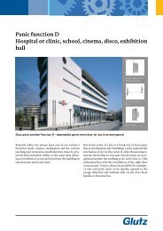
Option: Electrical <strong>lock</strong> operation b<strong>lock</strong><br />
An additional lifting magnet is attached to the top of the main <strong>lock</strong> box which can be used to b<strong>lock</strong> the<br />
three bolts from extending for as long as the lift magnet coil is live.<br />
When this additional electromagnet has been switched live, the three bolts and the latch are retracted<br />
either by the engaged external door lever, or the internal door lever. When the door closes, the latch will<br />
engage in the trap but the three bolts remain retracted. If the power supply to the magnet is interrupted,<br />
the bolts will extend when the door is closed.<br />
For doors with an automatic drive, an electric door opener is installed as counterpart to the <strong>lock</strong> latch.<br />
Solenoid coil: 12 or 24 VDC, 100% E.D., 4.8 Watt<br />
Note: this version is not the same as that covered by the general Building Control test certificate.<br />
13
14<br />
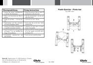
Wiring diagram<br />
DIN colours of cables<br />
white<br />
brown<br />
green<br />
yellow<br />
grey<br />
pink<br />
blue<br />
red<br />
black<br />
violet<br />
grey/pink<br />
red/blue<br />
white/green<br />
brown/green<br />
Spare for special functions<br />
Door position/<strong>lock</strong>ing<br />
Signal:<br />
Cylinder in normal position<br />
Cylinder turned 360<br />
(in <strong>lock</strong>ing direction)<br />
Entry with key<br />
Lever A<br />
Lever B<br />
Coupling magnet in the<br />
<strong>lock</strong>
Terminal Contact max. load Funktion Bemerkungen<br />
Electrical connections / Control and monitoring functions<br />
Serial connection of 2 reed contacts operated by permanent magnet in the<br />
strike plate or frame and the projecting bolt<br />
VDC mA<br />
1 NO 30 300 Monitoring door<br />
position and door<br />
<strong>lock</strong>ing<br />
When the key is turned in <strong>lock</strong>ing direction in the cylinder (e.g. b<strong>lock</strong> cylinder),<br />
this switch contact is operated and, at the same time, the power supply to the<br />
solenoid magnet is interrupted.<br />
Turning the key again in the opening direction returns the system to the base<br />
position.<br />
2 NO 30 300 Disconnecting<br />
3 NC 30 300 electrical magnet<br />
control<br />
4 COM<br />
Important! This function is normally not active; it must be ordered separately!<br />
5 NO 30 300 Entering with key When turning the key in the cylinder in opening direction, this switch contact<br />
is operated and, at the same time, the lever is switched from disengaged to<br />
6 NC 30 300<br />
engaged.<br />
7 COM<br />
When using electrical <strong>lock</strong>ing on escape and rescue routes, this contact can be<br />
used for the control of the exit <strong>lock</strong>ing element.<br />
This contact closes when the lever pointing to the left is operated<br />
(e.g. signalling authorised exit to the monitoring system)<br />
8 NO 30 300 Lever contact<br />
(base of <strong>lock</strong> box)<br />
This contact closes when the lever pointing to the right is operated<br />
(e.g. signalling authorised exit to the monitoring system)<br />
9 NO 30 300 Lever contact<br />
(<strong>lock</strong> box lid)<br />
10 COM Lever contacts COM for lever contacts 8 and 9<br />
Solenoid Minus connection for operating magnet (ensure correct voltage and polarity!)<br />
(Pole protection diode and idling diode)<br />
340<br />
170<br />
11 - 12<br />
24<br />
Plus connection for operating magnet (ensure correct voltage and polarity!)<br />
(Pole protection diode and idling diode)<br />
340<br />
170<br />
12 + 12<br />
24<br />
COM for door position / bolt position contact 1<br />
13 COM Door position/door<br />
<strong>lock</strong>ing<br />
14 Spare For special functions<br />
15
16<br />
Faults – causes – remedies<br />
1. Lock functions<br />
Fault Cause Remedy<br />
1.1 After closing the door it<br />
does not <strong>lock</strong> automatically;<br />
the bolts are not, or not fully,<br />
extended.<br />
1.2 When opening the door,<br />
the bolts do not remain<br />
retracted but protrude.<br />
1.3 The external door lever<br />
does not engage.<br />
1.4 It is not possible to engage<br />
the lever using the safety<br />
cylinder.<br />
1. The <strong>lock</strong> latch cannot engage<br />
in the strike plate.<br />
2. At least one bolt cannot enter<br />
the bolt opening in the strike<br />
plate.<br />
3. The cut-out for the latch is too<br />
big; the control latch extends<br />
into the latch opening.<br />
4. The connection rods in<br />
the forend were bent during<br />
assembly of the main <strong>lock</strong> and<br />
forend extension.<br />
1. Control latch is jamming.<br />
2. Lubricant or oil spray in the<br />
<strong>lock</strong>.<br />
1. No connection, or wrong<br />
voltage, from the access control<br />
system.<br />
2. Wrong poles connected to<br />
terminals 11 and 12.<br />
3. The “Switch off electrical<br />
control” function is active and<br />
the cylinder has been turned in<br />
<strong>lock</strong>ing direction.<br />
4. The string is unable to lift the<br />
lever to its top end position.<br />
The safety cylinder is not<br />
correctly positioned in the <strong>lock</strong>.<br />
1. Increase the size of the opening<br />
for the latch in the strike plate or<br />
frame.<br />
2. Increase the size of the bolt<br />
opening(s) in the strike plate or<br />
frame.<br />
3. Move the strike plate upwards or<br />
close the latch opening by welding.<br />
4. Remove the <strong>lock</strong>, carefully separate<br />
the upper forend extension (see<br />
installation instructions), straighten<br />
the connection rods. Heavily<br />
bent rods must be replaced.<br />
1. Lightly grease and move the control<br />
latch, depressing the main latch<br />
a little.<br />
2. Remove the <strong>lock</strong> and send to be<br />
cleaned.<br />
1. Measure the voltage at terminals<br />
11(-) and 12(+) and compare with<br />
the type plate.<br />
2. Make correct connection:<br />
+ on terminal 12, – on terminal 11.<br />
If the diode is defective, the <strong>lock</strong><br />
must be sent away for repair.<br />
3. Turn the safety key in the cylinder<br />
one complete turn in opening<br />
direction.<br />
4. Check the installation of the protection<br />
fitting<br />
(movement of lever in the plate is<br />
jamming).<br />
Release cylinder fixing using a 3<br />
mm Allen key, position the cylinder<br />
exactly in the centre and retighten<br />
the bolt.
Faults – causes – remedies<br />
2. Control and monitoring functions<br />
Fault Cause Remedy<br />
2.1 Feedback “Door position –<br />
door <strong>lock</strong>ing” does not work.<br />
2.2 Switch contact “Disconnect<br />
electric controls” does not<br />
work.<br />
2.3 Switch contact “Entry with<br />
key” does not work.<br />
1. Magnet in the strike plate is<br />
not correctly positioned or the<br />
gap between door and plate is too<br />
big.<br />
2. Bolts cannot fully extend.<br />
3. Contacts were overloaded.<br />
1. Cylinder is not correctly<br />
positioned.<br />
2. Contacts were overloaded.<br />
1. Cylinder is not correctly<br />
positioned.<br />
2. Contact was overloaded.<br />
1. Reposition the magnet; the correct<br />
position should be established<br />
by trial and error.<br />
2. See 1.1 <strong>lock</strong> function faults.<br />
3. Send the <strong>lock</strong> away for repair.<br />
1. See 1.4 <strong>lock</strong> function faults.<br />
2. Send the <strong>lock</strong> away for repair.<br />
1. See 1.4 <strong>lock</strong> function faults.<br />
2. Send the <strong>lock</strong> away for repair.<br />
17
<strong>Glutz</strong> AG<br />
Segetzstrasse 13, 4502 Solothurn, Schweiz<br />
Tel. +41 32 625 65 20, Fax +41 32 625 65 35<br />
info@glutz.com, www.glutz.com<br />
<strong>Glutz</strong> AG, Access Center<br />
Hertistrasse 31, 8304 Wallisellen, Schweiz<br />
Tel. +41 44 496 12 11, Fax +41 44 496 12 12<br />
info@glutz.com, www.glutz.com<br />
<strong>Glutz</strong> Deutschland GmbH<br />
Hertzstrasse 13, 30827 Garbsen, Deutschland<br />
Tel. +49 5131 95 138, Fax +49 5131 96 689<br />
info@glutz.de, www.glutz.com<br />
<strong>Glutz</strong> GmbH, Österreich<br />
St. Oswalder Strasse 5c, 4293 Gutau, Österreich<br />
Tel. +43 7946 20506, Fax +43 7946 20506 10<br />
info@glutz.at, www.glutz.com<br />
<strong>Glutz</strong> UK Ltd.<br />
11 Finch Drive, Springwood Industrial Estate<br />
Braintree CM7 2SF, United Kingdom<br />
Tel. +44 1376 348 808, Fax +44 1376 348 848<br />
info@glutz.co.uk, www.glutz.com<br />
<strong>Glutz</strong> Singapore Pte Ltd.<br />
50 Tagore Lane, #03-09, Entrepreneur Centre<br />
Singapore 787 494<br />
Tel. +65 6 55 44 111, Fax +65 6 55 44 610<br />
info@glutz.com.sg, www.glutz.com<br />
Swiss Access Systems