Instruction Manual - Rodney Hunt Company
Instruction Manual - Rodney Hunt Company
Instruction Manual - Rodney Hunt Company

Create successful ePaper yourself
Turn your PDF publications into a flip-book with our unique Google optimized e-Paper software.
Operating Mechanisms<br />
ELECTRIC MOTOR DRIVEN<br />
FLOOR STANDS<br />
1. After the operating stem has been properly installed,<br />
the electric unit is lowered over the top of the stem and<br />
turned into place. The handwheel can be used to lower<br />
the unit onto its anchor bolts.<br />
2. The unit should be shimmed approximately 1” above<br />
the floor so that the operating nut in the unit and stem<br />
are properly aligned.<br />
3. Approximately 1” of grout should be placed between<br />
the base of the pedestal and the operating floor.<br />
4. The unit should be wired following the wiring diagrams<br />
and instructions closely.<br />
5. The sluice gate should be opened by the manual<br />
handwheel at least 3 inches before using the electrical<br />
controls. In this manner, the direction of rotation of the<br />
motor can be determined without damaging the stem or<br />
hoisting unit.<br />
6. Once the unit has been installed, the manufacturer’s<br />
directions should be followed closely in setting the<br />
closing and opening limit switches. The torque switches<br />
have been properly set at the factory and should not<br />
need adjustment. Follow the manufacturer’s instructions<br />
if it appears that adjustment is necessary.<br />
7. For inverted gates refer to page 23 for operating procedures.<br />
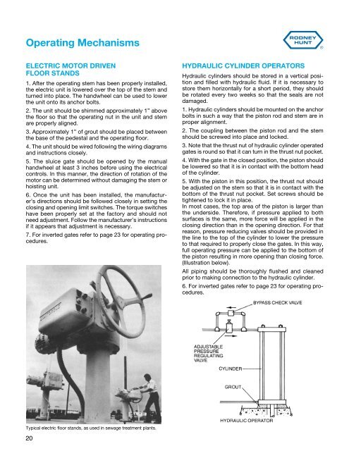
Typical electric floor stands, as used in sewage treatment plants.<br />
20<br />
HYDRAULIC CYLINDER OPERATORS<br />
Hydraulic cylinders should be stored in a vertical position<br />
and filled with hydraulic fluid. If it is necessary to<br />
store them horizontally for a short period, they should<br />
be rotated every two weeks so that the seals are not<br />
damaged.<br />
1. Hydraulic cylinders should be mounted on the anchor<br />
bolts in such a way that the piston rod and stem are in<br />
proper alignment.<br />
2. The coupling between the piston rod and the stem<br />
should be screwed into place and locked.<br />
3. Note that the thrust nut of hydraulic cylinder operated<br />
gates is round so that it can turn in the thrust nut pocket.<br />
4. With the gate in the closed position, the piston should<br />
be lowered so that it is in contact with the bottom head<br />
of the cylinder.<br />
5. With the piston in this position, the thrust nut should<br />
be adjusted on the stem so that it is in contact with the<br />
bottom of the thrust nut pocket. Set screws should be<br />
tightened to lock it in place.<br />
In most cases, the top area of the piston is larger than<br />
the underside. Therefore, if pressure applied to both<br />
surfaces is the same, more force will be applied in the<br />
closing direction than in the opening direction. For that<br />
reason, pressure reducing valves should be provided in<br />
the line to the top of the cylinder to lower the pressure<br />
to that required to properly close the gates. In this way,<br />
full operating pressure can be applied to the bottom of<br />
the piston resulting in more opening than closing force.<br />
(Illustration below).<br />
All piping should be thoroughly flushed and cleaned<br />
prior to making connection to the hydraulic cylinder.<br />
6. For inverted gates refer to page 23 for operating procedures.