Group 3 - Rear Axle - Copyright © jholst.net, all rights reserved.
Group 3 - Rear Axle - Copyright © jholst.net, all rights reserved.
Group 3 - Rear Axle - Copyright © jholst.net, all rights reserved.

You also want an ePaper? Increase the reach of your titles
YUMPU automatically turns print PDFs into web optimized ePapers that Google loves.
10—REAR AXLE<br />
outer edge of the flange and the ring gear<br />
bolt holes (Fig. 13).<br />
(7) Rotate differential several complete revolutions<br />
while noting the total Indicator reading. This<br />
reading must not exceed .003 Inch runout. If<br />
runout is In excess of .003 Inch, the differential<br />
case must be replaced.<br />
(8) Remove the ca'se "from carrier. If ring gear<br />
runout exceeded .005 Inch when checked as<br />
outlined In Paragraph 12A (2), and the differential<br />
case mounting flange runout does not<br />
exceed .003 inch, replace the ring gear and<br />
pinion.<br />
(9) Measure the side gear clearances between gear<br />
and case (Fig. 14). Clearances should be .004<br />
to .012 inch. .001 to .012 Inch on models PS-1<br />
and PS-3. If clearance exceeds .012 Inch, Inst<strong>all</strong><br />
new thrust washers and/or differential<br />
case or gear.<br />
(10) From the back side of the ring gear flange<br />
drive the differential pinion shaft lock pin out<br />
of the case with a 7/32 x 3^2 inch flat nose<br />
drift and a hammer. (The hole is reamed only<br />
part way through, making it necessary to<br />
remove the lock pin from one direction.) The<br />
lock pin Is a roll-pin type.<br />
(11) Drive the pinion shaft out with a brass drift<br />
and a hammer. Remove the axle drive shaft<br />
thrust block.<br />
(12) Rotate one differential side gear until each<br />
pinion appears at the large opening of the case.<br />
Remove each pinion and thrust washer at that<br />
time.<br />
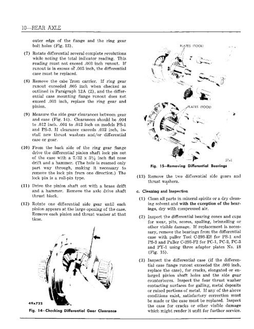
49xJ22<br />
Fig, 14—Checking Differential Gear Clearance<br />
PLATES (TOOL)<br />
A<br />
Fig. 15—Removing Differential Bearings<br />
57x8<br />
(13) Remove the two differential side gears and<br />
thrust washers.<br />
#<br />
c. Cleaning and Inspection<br />
(1) Clean <strong>all</strong> parts in mineral spirits or a dry cleaning<br />
solvent and with the exception of the bearings,<br />
dry with compressed air.<br />
(2) Inspect the differential bearing cones and cups<br />
for wear, pits, scores, sp<strong>all</strong>ing, brinnelling or<br />
other visible damage. If replacement is necessary,<br />
remove the bearings from the differential<br />
case with puller Tool C-293-E2 for PS-1 and<br />
PS-3 and Puller C-293-F2 for PC-1, PC-2, PC-3<br />
and PY-1 using three adaptor plates No. 18<br />
(Fig. 15).<br />
(3) Inspect the differential case (if the differential<br />
case flange runout exceeded the .003 inch,<br />
replace the case), for cracks, elongated or enlarged<br />
pinion shaft holes and the side gear<br />
counterbores. Inspect the four thrust washer<br />
contacting surfaces for g<strong>all</strong>ing, metal deposits<br />
or raised portions of metal. If any of the above<br />
conditions exist,. satisfactory correction must<br />
be made or the case must be replaced. Inspect<br />
the case for cracks or other visible damage<br />
which might render it unfit for further service.