Group 3 - Rear Axle - Copyright © jholst.net, all rights reserved.
Group 3 - Rear Axle - Copyright © jholst.net, all rights reserved.
Group 3 - Rear Axle - Copyright © jholst.net, all rights reserved.

Create successful ePaper yourself
Turn your PDF publications into a flip-book with our unique Google optimized e-Paper software.
18—REAR AXLE<br />
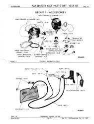
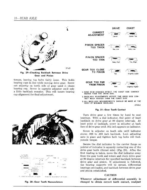
Fig. 29—Checking Backlash Between Drive<br />
Gear and Pinion<br />
57x21<br />
torque, leaving top bolts fairly loose. This holds<br />
bearing cups in line while moving drive gear. Screw<br />
out adjuster on tooth side of gear until it clears<br />
bearing cup. Screw in opposite adjuster until only<br />
a little backlash remains. This will insure bearing<br />
cup alignment for final adjustment.<br />
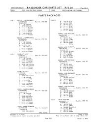
C'JT'vVAPC<br />
OF PlhiGX-<br />
OF PSN.ON<br />
OUT WAS T W 07I.V ZK"<br />
CIEARAVCE<br />
• FACE<br />
- FLAN*<br />
'AWA3D MOVEMENT OF Gc.AR<br />
Fig. 30—Gear Tooth Nomenclature<br />
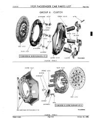
CORRECT<br />
ADJUSTMENT<br />
PINION SPACER<br />
TOO THICK<br />
PINION SPACER<br />
TOO THIN<br />
GEAR TOO CLOSE<br />
TO PINION<br />
GEAR TOO FAR<br />
FROM PINION<br />
DRIVE COAST<br />
Center<br />
Toe. Low<br />
Heel, High<br />
Heel<br />
Center Toe<br />
Toe, High<br />
Slightly Lower<br />
Slightly Higher<br />
1. CONE SHIM CHANGES AFFECT THE COAST SIDE CONTACT<br />
FASTER THAN THE DRIVE SIDE.<br />
2. BACKLASH ADJUSTMENTS AFFECT THE ORIVE SIDE CON<br />
TACT MUCH FASTER THAN THE COAST SIDE.<br />
3. ALL BACKLASH MEASUREMENTS SHOULD BE MADE AT THE<br />
POINT OF MINIMUM BACKLASH.<br />
59S164<br />
Fig 31—Gear Tooth Contact<br />
Turn drive gear a few times by hand to seat<br />
bearings. With a dial indicator, find point of least<br />
backlash on drive gear at 90 degree intervals. At<br />
least point of backlash, screw in adjuster at back<br />
face of drive gear until .001 inch appears on indicator.<br />
Screw in adjuster on tooth side until indicator<br />
shows .006 to .008 inch backlash. Lock adjusting<br />
nuts in place and tighten both top bolts 110 footpounds<br />
torque.<br />
Secure the dial indicator to the carrier flange so<br />
pointer of indicator is squarely contacting one of the<br />
drive gear teeth (thrust side) (Fig, 29). After the<br />
first reading is taken, move the dial indicator away<br />
from the gear tooth and rotate and check drive gear<br />
at 90 degree intervals for specified backlash between<br />
drive gear and pinion. If adjustment is followed,<br />
the bearing supports will be spread, differential<br />
bearings pre-loaded, and backlash between drive gear<br />
and pinion established.<br />
CAUTION<br />
Whenever adjustment of differential assembly is<br />
changed to obtain correct tooth contact, readjust