Group 3 - Rear Axle - Copyright © jholst.net, all rights reserved.
Group 3 - Rear Axle - Copyright © jholst.net, all rights reserved.
Group 3 - Rear Axle - Copyright © jholst.net, all rights reserved.

You also want an ePaper? Increase the reach of your titles
YUMPU automatically turns print PDFs into web optimized ePapers that Google loves.
<strong>Group</strong> 3<br />
REAR AXLE<br />
CONTENTS<br />
Paragraph Page<br />
<strong>Axle</strong> Drive Shafts 11 6<br />
Removal<br />
Cleaning and Inspection<br />
End Play<br />
Assembly<br />
Carrier Assembly Inst<strong>all</strong>ation 25 19<br />
Differential Carrier Assembly 12 8<br />
Disassembly<br />
Cleaning and Inspection<br />
Assembly<br />
Inst<strong>all</strong>ation<br />
Differential Case Assembly 16 17<br />
Inst<strong>all</strong>ation in Carrier<br />
Differential Bearing Pre-load and Gear<br />
Backlash Adjustment<br />
Gear Tooth Contact Pattern 17 19<br />
Checking Tooth Contact Pattern 18 19<br />
Heavy Face Contact 19 19<br />
Heavy Flank Contact 20 19<br />
Heavy Toe Contact 21 19<br />
Heavy Heel Contact . 22 19<br />
Pinion With Bearing Spacer Inst<strong>all</strong>ation Using<br />
Tool C-758-D3 13 13<br />
Bearing Pre-load<br />
Depth of Mesh<br />
Pinion Without Bearing Spacer Inst<strong>all</strong>ation Using<br />
Tool C-758-D3 - 14 14<br />
Depth of Mesh<br />
Pinion Bearing Pre-load<br />
Pinion Depth of Mesh and Bearing Pre-load Without<br />
Using Tool C-758-D3 15 17<br />
Depth of Mesh (without using Tool C-758-D3)<br />
Pinion Bearing Pre-load (without using<br />
Tool C-758-D3)<br />
<strong>Rear</strong> <strong>Axle</strong> Housing Alignment 24 19<br />
Service Diagnosis 1 4<br />
Welding <strong>Rear</strong> <strong>Axle</strong> Housing - 23 19
2—REAR AXLE<br />
CONTENTS (Cont'd)<br />
Sure Grip Differential<br />
Description 26<br />
Lubrication 28<br />
Sure Grip Differential Identification 27<br />
Sure Grip Differential 29<br />
Removal<br />
Disassembly<br />
Cleaning and Inspection<br />
Assembly<br />
REAR AXLE<br />
DATA AND SPECIFICATIONS<br />
MODELS PS-1, PS-3, PC-1, PC-2, PC-3, PY-1<br />
Type Semi-Floating<br />
Gear Type - - Hypoid<br />
Ring Gear Diameter 8.75 inch<br />
Pinion Bearing Tapered Roller (2)<br />
Drive Pinion Bearing Pre-load 20-30 in. lbs. without seal<br />
Adjustment Shim Pack<br />
Differential Bearings Tapered Roller (2)<br />
Differential Bearing Adjustment Threaded Adjuster<br />
Drive Gear and Pinion Serviced in Matched Sets Only<br />
Drive Gear Runout .005 inch (Maximum)<br />
Drive Gear and Pinion Adjustment : Select Washer<br />
Drive Gear and Pinion Backlash .006 to .008 inch<br />
Differential Side Gear Clearance<br />
Models PC-1, PC-2, PC-3, PY-1 .001 to .012 inch<br />
Models PS-1, PS-3 .004 to .012 inch<br />
Differential Lubricant Capacity S l<br />
/ 2 pints<br />
<strong>Axle</strong> Ratio<br />
Models PS-1, PC-1, PC-2, PC-3, PY-1 2.93 to 1<br />
Model PS-3 3.31 to 1<br />
Wheel Bearing Type Tapered Rollers<br />
Wheel Bearing Adjustment Select Shims<br />
Wheel Bearing <strong>Axle</strong> Shaft End Play .013 to .018 inch<br />
20<br />
21<br />
20<br />
21
TIOHTEMIMG REFEMEMCE^ Foot-Pounds<br />
<strong>Axle</strong> Shaft Nuts 145 (Mm.)<br />
Brake Support Plate to Housing Mounting Bolt Nuts 30-35<br />
Differential Carrier to <strong>Axle</strong> Housing Bolt Nuts 45<br />
<strong>Rear</strong> <strong>Axle</strong> Drive Gear to Case Bolts . 45<br />
Differential Bearing Cap Bolts _ 90<br />
<strong>Rear</strong> <strong>Axle</strong> Drive Pinion Companion Flange Nut 240 (Min.)<br />
SPECIAL TOOLS<br />
C-293-E2 or F2 Puller Sets —Roller Bearing<br />
C-406-A Differential Bearing Adjusting Wrench<br />
C-413. <strong>Rear</strong> <strong>Axle</strong> Shaft Outer Bearing Cup Driver<br />
C-452 Universal Joint Flange Puller<br />
C-485 Torque Wrench (Foot-Pounds)<br />
REAR AXLE—3<br />
C-496 Pinion and Transmission Companion Flange or Yoke Puller<br />
C-499 . <strong>Axle</strong> Shaft Puller<br />
C-637 <strong>Axle</strong> Shaft and Inner Oil Seal Puller<br />
C-685 Torque Wrench (Inch-Pounds)<br />
C-745 <strong>Rear</strong> <strong>Axle</strong> Shaft Oil Seal Inst<strong>all</strong>ing Sleeve<br />
C-748 Pinion Oil Seal Puller<br />
C-758-D3 ....Pinion Setting Gauge Set<br />
C-839 <strong>Rear</strong> <strong>Axle</strong> Shaft Inner Oil Seal Driver<br />
C-845 Universal Wheel and Hub Puller<br />
C-3281 Companion Flange Holding Wrench<br />
C-3339 Dial Indicator<br />
C-3565 <strong>Axle</strong> Shaft Outer Seal Driver<br />
C-3571 Adapter Kit<br />
C-3656 Pinion Oil Seal Driver<br />
DD-996 Pinion Bearing Inst<strong>all</strong>er<br />
DD-999. Flange or Yoke Inst<strong>all</strong>er<br />
DD-1005 Differential Case Side and Cross Shaft Roller Bearing Driver<br />
DD-1014 Repair Stand — Differential Carrier<br />
SP-2919 ...Pinion Setting Adapter —Part of Tool C-758-D3 and C-3571<br />
SP-2920 ..Pinion Spacer Sleeve —Part of Tool C-758-D3 and C-3571<br />
SP-2921... Setting Adapter —Part of Tool C-758-D3 and C-3571
4—REAR AXLE<br />
1. REAR WHEEL NOISE<br />
a. Wheel loose on axle shaft.<br />
b 8 Wheel hub bolts loose.<br />
c. Improper shimming at axle bearing.<br />
d. Insufficient lubrication.<br />
e. Brinnelled or scored wheel bearings.<br />
f. Worn drum or worn axle shaft keyways.<br />
g. Bent or sprung axle shaft.<br />
2* REAR AXLE NOISE<br />
a. Lubricant level too low.<br />
b. End play in drive pinion bearings. Also see<br />
Paragraph 3b—gear noise on coast.<br />
c. Excessive gear lash between ring gear and<br />
pinion. Also see Paragraph 3a and c. Gear noise on<br />
pull.<br />
d. Loose drive pinion companion flange nut.<br />
e. Scuffed gear tooth contact surfaces.<br />
3. REAR AXLE GEAR NOISE<br />
a. Gear noise on pull—a heavy pitch noise and<br />
increases as car speed increases, indicates scored gear<br />
teeth due to loss of lubricant, excessive gear lash<br />
or wrong type of lubricant.<br />
b. Gear noise on pull or coast—noise is heavy and<br />
(irregular) indicating excessive end play in pinion<br />
bearings.<br />
Co Bearing noise on pull or coast—a rough grating<br />
sound may change slightly in volume as speed<br />
changes; indicates that the rear axle pinion bearings<br />
are chipped, cracked, scored, badly worn and loose,<br />
or no gear lash.<br />
4 CLICKING NOISE IN DRIVE LINE<br />
a. Noise in drive line when vehicle is backed up<br />
or moved forward — Clean axle shaft taper, keys<br />
and drums. Apply a heavy coating of chalk around<br />
entire circumference and length of the tapered section<br />
of rear axle shaft. Inst<strong>all</strong> drums and tighten<br />
axle shaft nuts 145 foot-pounds torque, minimum.<br />
SERVICE DIAGNOSIS<br />
Check universal joints, and flange splines. Tighten<br />
companion flange nut to 240 foot-pounds torque,<br />
minimum.<br />
5. REAR AXLE DRIVE SHAFT BREAKAGE<br />
a. Improperly adjusted wheel bearings.<br />
b. Abnormal clutch operation.<br />
c. Misaligned axle housing.<br />
d. Vehicle overloaded.<br />
6. DIFFERENTIAL CASE BREAKAGE<br />
a. Improper differential bearing adjustment.<br />
b. Abnormal clutch operation.<br />
c. Excessive drive gear clearance.<br />
d. Vehicle overloaded.<br />
7. D1FFRENTIAL SIDE GEAR BROKEN<br />
a. Worn thrust washers.<br />
b. Misaligned or bent axle shaft.<br />
c. Overloading vehicle.<br />
8* TOOTH BREAKAGE (Drive Gear and Pinion)<br />
a. Overloading and abnormal clutch operation.<br />
b. Improper gear adjustment.<br />
9. OVERHEATING OF AXLE UNIT<br />
a. Lubricant level too low.<br />
b. Bearings adjusted too light.<br />
c. Bearings adjusted too tight.<br />
d. Excessive wear in gears.<br />
e. Insufficient drive gear to pinion clearance.<br />
10. LOSS OF LUBRICANT<br />
a. Lubricant level too high.<br />
b. Clogged breather.<br />
c. Scored or worn parts.<br />
d. Oil seals worn.
THRUST WASHER<br />
BEARING<br />
CONE '<br />
SHAFT<br />
, j i j SIDE GEAR<br />
| P I N , O N<br />
DIFFERENTIAL CASE<br />
PIN<br />
| / / BEARING CONE<br />
CUP<br />
DRIVE GEAR<br />
AND PINION<br />
BOLT AND LOCKWASHER<br />
\<br />
\ LOCK<br />
\ \ \ ADJUSTER<br />
BOLT<br />
M lf<br />
W^ \ CUP-<br />
I I THRUST WASHER \^ x<br />
THRUST BLOCK<br />
SIDE GEAR<br />
THRUST WASHER<br />
THRUST WASHER<br />
\ \ \ \<br />
1 ,f<br />
| 4<br />
I<br />
BOLT<br />
CAP<br />
h i :<br />
J BEARING CONE<br />
ADJUSTING WASHER<br />
BEARING CONE<br />
CARRIER<br />
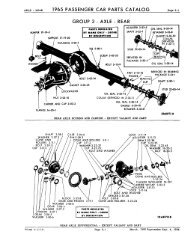
Fig. 1—<strong>Rear</strong> <strong>Axle</strong> (Disassembled View)<br />
(Pinion Without Spacer)<br />
Fig. 2—tear <strong>Axle</strong> (Disassembled View)<br />
(Pinion with Spacer)<br />
SHIMS \<br />
"PLUG<br />
-CAP<br />
"--ADJUSTER<br />
LOCK<br />
i<br />
REAR AXLE—5<br />
FiANOf<br />
SEAL<br />
CUP<br />
BOLT AND LOCKWASHER<br />
NUT<br />
\ WASHER<br />
GUARD<br />
57.x 1
6—REAR AXLE<br />
The rear axle assembly (Figs. 1 and 2) consists of<br />
four sub-assemblies; axle drive shafts with related<br />
parts, differential with ring gear, drive pinion with<br />
carrier, and axle housing. It is not necessary to<br />
remove the entire axle assembly to service any of the<br />
above components with the exception of the axle<br />
housing itself.<br />
11. AXLE DRIVE SHAFTS<br />
a. Removal<br />
(1) Raise the car and remove the rear wheels, hub<br />
and drum assembly, using puller Tool C-845.<br />
CAUTION<br />
Do not use a knock-off type wheel puller. Use of a<br />
knock-off type puller may cause damage to bearings<br />
and thrust block.<br />
(2) Block the brake pedal to prevent its being<br />
depressed and disconnect the brake lines at the<br />
wheel cylinders.<br />
(3) Remove the axle drive shaft key and remove<br />
the brake support and dust shield using Tool<br />
C-757 to protect the outer seal (Fig. 2).<br />
(4) Carefully remove the shim pack from each end<br />
of the axle housing. Identify each shim pack<br />
as to location to aid in reassembly.<br />
REAR AXLE SHAFT<br />
' 46x140<br />
Fig, 3—Removing <strong>Axle</strong> Drive Shaft and Bearing<br />
<strong>Group</strong> 3<br />
REAR AXLE<br />
JHll<br />
mm mm<br />
6X57<br />
Fig. 4—Removing Bearing from <strong>Axle</strong> Drive Shaft<br />
1. <strong>Axle</strong> Drive Shaft 2. Tool 3. Bearing<br />
(5) Remove the axle shafts and bearing assembly<br />
using Tool C-499 (Fig. 3). If necessary, the<br />
bearings may be removed from the axle shafts<br />
using bearing puller, Tool C-293-13 (Fig. 4).<br />
(6) Remove the axle shaft inner oil seals with<br />
puller Tool C-637 (Fig. 5). Remove the brake<br />
dust shield outer seal using Tool C-3565.<br />
bo Cleaning and Inspection<br />
(1) With mineral spirits or dry cleaning solvent,<br />
clean the axle shafts, bearings, cups, shims<br />
and shim contacting surfaces as well as the<br />
counterbores of the axle housing. With the<br />
exception of the bearings, dry <strong>all</strong> parts with<br />
compressed air.<br />
(2) Inspect the bearing cones and cups for sp<strong>all</strong>ing,<br />
brinnelling or other visible damage. If either<br />
the bearing cone or cup is not up to inspection<br />
REAR AXLE SHAFT<br />
INNER OIL SEAL<br />
49x713<br />
TOOL x<br />
Fig. 5—Removing <strong>Axle</strong> Drive Shaft Inner Oil Seal
standards, replace both the cone and cup.<br />
(3) Inspect each axle shaft for signs of fatigue,<br />
worn or scored oil seal contacting surfaces,<br />
wear or accumulated metal deposits on the<br />
thrust block end of the shaft, damaged threads,<br />
or excessively worn splines. Machined surfaces<br />
can usu<strong>all</strong>y be satisfactorily dressed. If<br />
abnormal conditions are noted, the shafts<br />
should be replaced.<br />
(4) Inspect the shims for distortion or other visible<br />
damage. Inst<strong>all</strong> new shims if necessary.<br />
(5) Inspect the shim contacting surfaces of both<br />
the brake support and axle housing for burrs.<br />
Remove burrs with crocus cloth if possible.<br />
(6) If inspection reveals that replacement of either<br />
the axle shaft or bearing is necessary, press<br />
bearing on the axle shaft using an arbor press,<br />
or Tool DD-996.<br />
(7) Make certain that the bearing and axle shaft<br />
contacting surfaces are thoroughly cleaned so<br />
the bearing bottoms against the shoulder of the<br />
axle shaft. (Tapered portion of the bearing<br />
must face the axle shaft threads.)<br />
c. <strong>Axle</strong> Drive Shaft End Play<br />
Where original axle shafts and bearings are used,<br />
start measurement of end play with original shim<br />
packs, after recording thickness of each. When<br />
either or both the axle shaft and bearing is replaced,<br />
use shim packs totaling .040 inch per side. Shims<br />
are available in thicknesses of .005, .0125, .015 and<br />
.030 inch.<br />
do <strong>Axle</strong> Drive Shaft Assembly<br />
(1) Inst<strong>all</strong> inner oil seals with Tool C-839 (Fig. 6).<br />
(2) Starting at one end of the axle housing, inst<strong>all</strong><br />
a .040 inch shim pack on the flange studs.<br />
t o o l ;<br />
V; 56x23^<br />
Fig. 6—Inst<strong>all</strong>ing <strong>Axle</strong> Shaft Inner Oil Seal<br />
TOOL<br />
REAR AXLE—7<br />
56x235A<br />
Fig. 7—Inst<strong>all</strong>ing <strong>Axle</strong> Drive Shaft Bearing Cup<br />
(3) Working from the same side of the axle<br />
housing, lubricate the axle shaft bearing with<br />
multi-purpose gear lube and inst<strong>all</strong> the axle<br />
shaft.<br />
(4) Inst<strong>all</strong> the bearing cup with the inst<strong>all</strong>ing<br />
Tool C-413 (Fig. 7). Make certain the bearing<br />
cup is driven into the axle housing until the<br />
face of the inst<strong>all</strong>ing tool bottoms against the<br />
shims, not the housing flange. Remove tool<br />
and inst<strong>all</strong> the brake support, lockwashers, and<br />
nuts. Tighten nuts 30 to 35 foot-pounds torque.<br />
(5) Working from the opposite side of the axle<br />
housing, lubricate the bearing and inst<strong>all</strong> the<br />
other axle shaft until it contacts the axle shaft<br />
thrust block.<br />
(6) With a fiber m<strong>all</strong>et, lightly tap the end of the<br />
axle shaft against the thrust block. This will<br />
force the opposite axle shaft bearing to seat in<br />
its cup.<br />
(7) Inst<strong>all</strong> the bearing cup with Tool C-413 (Fig.<br />
7). The bearing cup must be gently driven<br />
into position until the axle shaft end play just<br />
disappears without pre-loading the bearing.<br />
The bearing cup will protrude slightly beyond<br />
the face of the axle housing flange.<br />
(8) While the Tool C-413 is held firmly against<br />
the bearing cup, insert a feeler gauge between<br />
the axle housing flange and the face of the<br />
tool to measure the clearance.<br />
(9) To determine the thickness of the shim pack<br />
required to obtain .013 to .018 inch axle shaft<br />
end play, add a minimum of .013 inch to the<br />
feeler gauge reading. Compare the thickness<br />
of this shim pack with the thickness of the<br />
opposite pack. If the difference in the thickness<br />
of the shim packs exceeds .020 inch, divide the
8—REAR AXLE<br />
Fig, 8—Checking! ?'srwe G-sw Runout<br />
57x19<br />
difference between both axle shaft bearings to<br />
center the axle shafts and the thrust block.<br />
Equal thickness of shims on both axle shafts is<br />
necessary to maintain the centralized position<br />
of axle shaft thrust block.<br />
(10) Position shim packs on flange studs and drive<br />
the cups in until tool bottoms on the shim<br />
packs.<br />
(11) Inst<strong>all</strong> new outer oil seals on brake support<br />
plates with Tool C-3565 with lip of seal toward<br />
the center of vehicle.<br />
(12) Insert sleeve Tool C-745 in outer seal to protect<br />
seal when the brake support is inst<strong>all</strong>ed.<br />
(13) Inst<strong>all</strong> the dust shield and brake support.<br />
Tighten attaching nuts 30 to 35 foot-pounds<br />
torque. Inst<strong>all</strong> wheels, hub and drum.<br />
12. DIFFERENTIAL CAR1IER REMOVAL<br />
(1) Remove the axle drive shafts (See Paragraph<br />
11A).<br />
FLANGE<br />
L<br />
TOOL-<br />
Fig. 9—Removing or Inst<strong>all</strong>ing Companion Flange<br />
TC.<br />
IHiii<br />
57x6<br />
Fig. 10—Removing Pinion Bearing Oil Seal<br />
(2) Disconnect the rear universal joint and drop<br />
the propeller shaft.<br />
(3) Remove the drain plug and drain the lubricant<br />
into a container.<br />
(4) Remove the attaching nuts and lift rear axle<br />
carrier assembly from under vehicle.<br />
a.* Differential and Drive Pinion<br />
(1) Mount differential in stand Tool DD-1014 and<br />
attach the dial indicator Tool C-3339 to the<br />
differential carrier flange so the pointer of indicator<br />
squarely contacts the back face of ring<br />
gear (Fig. 8). Make certain there is no end<br />
play in the differential side bearings. If end<br />
play is evident, remove the adjuster lock and<br />
slightly loosen the bearing cap on the gear<br />
tooth side. Tighten the adjuster sufficiently<br />
to eliminate end play.<br />
(2) Rotate ring gear several complete revolutions<br />
while noting the total indicator reading. This<br />
reading must not exceed .005 inch runout. If<br />
indicator reading exceeds the .005 inch runout,<br />
it will be necessary to check runout of differential<br />
case mounting flange (see Paragraph<br />
12R [3]).<br />
(3) With companion flange up, hold the flange with<br />
holding Tool C-3281 and remove the pinion<br />
shaft nut and convex washer.<br />
(4) Inst<strong>all</strong> the companion flange puller Tool C-452<br />
and remove the flange (Fig. 9).<br />
(5) Inst<strong>all</strong> oil seal puller Tool C-748 by screwing it<br />
securely into the pinion oil seal (Fig. 10) and<br />
tighten puller screw to remove the seal.<br />
(6) While holding one hand over the companion<br />
flange end of carrier, invert the carrier in the<br />
stand. The oil slinger, front bearing cone
SCRIBE MARKS<br />
PUNCH MARKS<br />
57x3<br />
Fig. 11—Marking Bearing Caps and Adjusting Nuts<br />
shim pack and bearing spacer (when so<br />
equipped) will drop from the carrier.<br />
(7) Apply identifying punch marks on the bearing<br />
supports of the differential carrier, differential<br />
bearing caps, and bearing adjusters for reassembly<br />
identification (Fig. 11).<br />
(8) Remove each of the differential bearing adjuster<br />
lock screws and locks.<br />
(9) Loosen bearing cap bolt (one each side) and<br />
back off bearing adjusters slightly with a<br />
spanner wrench Tool C-406, to remove differential<br />
case bearing pre-load. Remove the bearing<br />
cap bolts, caps and bearing adjusters.<br />
(10) Remove the differential assembly with bearing<br />
cups. Make certain that each bearing cup<br />
remains with Its respective bearing.<br />
4<br />
V ^ - -<br />
PLATES<br />
'.•--"^r 5!<br />
: I<br />
Fig. 12—Removing Bearing from Pinion Shaft<br />
REAR AXLE—9<br />
(11) Remove the drive pinion and rear bearing cone<br />
from the carrier.<br />
(12) Using puller Tool C-293 and four No. 36<br />
adaptor plates, remove the rear bearing cone<br />
from the pinion shaft (Fig. 12). Remove the<br />
pinion locating washer.<br />
(13) The bearing cups can be removed from the<br />
carrier with a blunt brass drift and a hammer.<br />
b. Differential Case Disassembly<br />
(1) Grip the ring gear In an upright position<br />
using brass jaws In a vise. Remove the (12)<br />
ring gear to differential attaching cap screws.<br />
NOTE: The ring gear attaching screws have left<br />
hand threads; turn clockwise to loosen.<br />
(2) Remove the assembly from the vise and with<br />
a fiber m<strong>all</strong>et, tap the ring gear off the case.<br />
(3) If ring gear runout was found to be more than<br />
.005 Inch (Paragraph 12A [2]) test the case<br />
as follows: Inst<strong>all</strong> the differential with bearing<br />
cups In the carrier.<br />
(4) Inst<strong>all</strong> the bearing caps, attaching bolts and<br />
bearing adjusters. Snug the bearing cap bolts<br />
down lightly and screw in both adjusters with<br />
a spanner wrench Tool C-406A.<br />
(5) Tighten support cap bolts and adjusters sufficiently<br />
to prevent any end play in the bearings.<br />
(6) Attach the dial Indicator Tool C-3339 to the<br />
differential carrier flange so the pointer of<br />
indicator squarely contacts the ring gear surface<br />
of the differential case flange between the<br />
57x7<br />
Fig. 13—Checking Drive Gear Nl\m'rt«°.mg Flange Runout
10—REAR AXLE<br />
outer edge of the flange and the ring gear<br />
bolt holes (Fig. 13).<br />
(7) Rotate differential several complete revolutions<br />
while noting the total Indicator reading. This<br />
reading must not exceed .003 Inch runout. If<br />
runout is In excess of .003 Inch, the differential<br />
case must be replaced.<br />
(8) Remove the ca'se "from carrier. If ring gear<br />
runout exceeded .005 Inch when checked as<br />
outlined In Paragraph 12A (2), and the differential<br />
case mounting flange runout does not<br />
exceed .003 inch, replace the ring gear and<br />
pinion.<br />
(9) Measure the side gear clearances between gear<br />
and case (Fig. 14). Clearances should be .004<br />
to .012 inch. .001 to .012 Inch on models PS-1<br />
and PS-3. If clearance exceeds .012 Inch, Inst<strong>all</strong><br />
new thrust washers and/or differential<br />
case or gear.<br />
(10) From the back side of the ring gear flange<br />
drive the differential pinion shaft lock pin out<br />
of the case with a 7/32 x 3^2 inch flat nose<br />
drift and a hammer. (The hole is reamed only<br />
part way through, making it necessary to<br />
remove the lock pin from one direction.) The<br />
lock pin Is a roll-pin type.<br />
(11) Drive the pinion shaft out with a brass drift<br />
and a hammer. Remove the axle drive shaft<br />
thrust block.<br />
(12) Rotate one differential side gear until each<br />
pinion appears at the large opening of the case.<br />
Remove each pinion and thrust washer at that<br />
time.<br />
49xJ22<br />
Fig, 14—Checking Differential Gear Clearance<br />
PLATES (TOOL)<br />
A<br />
Fig. 15—Removing Differential Bearings<br />
57x8<br />
(13) Remove the two differential side gears and<br />
thrust washers.<br />
#<br />
c. Cleaning and Inspection<br />
(1) Clean <strong>all</strong> parts in mineral spirits or a dry cleaning<br />
solvent and with the exception of the bearings,<br />
dry with compressed air.<br />
(2) Inspect the differential bearing cones and cups<br />
for wear, pits, scores, sp<strong>all</strong>ing, brinnelling or<br />
other visible damage. If replacement is necessary,<br />
remove the bearings from the differential<br />
case with puller Tool C-293-E2 for PS-1 and<br />
PS-3 and Puller C-293-F2 for PC-1, PC-2, PC-3<br />
and PY-1 using three adaptor plates No. 18<br />
(Fig. 15).<br />
(3) Inspect the differential case (if the differential<br />
case flange runout exceeded the .003 inch,<br />
replace the case), for cracks, elongated or enlarged<br />
pinion shaft holes and the side gear<br />
counterbores. Inspect the four thrust washer<br />
contacting surfaces for g<strong>all</strong>ing, metal deposits<br />
or raised portions of metal. If any of the above<br />
conditions exist,. satisfactory correction must<br />
be made or the case must be replaced. Inspect<br />
the case for cracks or other visible damage<br />
which might render it unfit for further service.
(4) Inspect the differential pinion shaft for excessive<br />
wear. Check pinion gears and differential<br />
side gears for excessive wear, cracks, chipped<br />
teeth or other visible damage. Replace as necessary.<br />
(5) Inspect axle shaft thrust block for excessive<br />
wear or other visible damage. The thrust block<br />
can be damaged by using a "knock off" type<br />
wheel puller. The wear surfaces on the opposite<br />
side of the block must be smooth. If the thrust<br />
block is replaced, axle shaft end must be reset.<br />
(6) Inspect differential pinion shaft lock pin for<br />
damage or looseness in the case. Replace the<br />
pin or case as necessary.<br />
(7) Inspect ring gear and pinion for scored, worn or<br />
chipped teeth. Check for damaged splines and<br />
attaching bolt threads. If replacement of ring<br />
gear or pinion is necessary, replace both the<br />
ring gear and drive pinion as they are furnished<br />
only in matched sets.<br />
(8) Inspect the drive pinion, bearing cups for pits,<br />
sp<strong>all</strong>ing, brinnelling, excessive wear, or other<br />
visible damage. If inspection reveals that<br />
either cup is unfit for further service, replace<br />
both the cup and the mated cone.<br />
(9) Inspect the differential carrier for cracks or<br />
other visible damage which would render it<br />
unfit for further service. Raised metal on<br />
shoulders incurred in removing the pinion cups<br />
should be flattened by use of a flat nose punch.<br />
(10) Inspect the drive pinion for scored, pitted, damaged<br />
or excessively worn teeth, damaged bearing<br />
journals or splines. If replacement of the<br />
pinion is necessary, a new ring gear must also<br />
be used as they are furnished only in matched<br />
sets. Inspect the pinion bearing spacer for<br />
distortion and damage also.<br />
(11) Inspect companion flange for cracks, worn<br />
splines, pitted, rough or corroded oil seal contacting<br />
surface. Replace the companion flange<br />
as necessary.<br />
(12) Inspect pinion bearing shim pack for damaged<br />
or distorted shims. Replace shims with correct<br />
ones during establishment of pinion bearing<br />
pre-load.<br />
d. Differential Case Assembly<br />
(1) Inst<strong>all</strong> the thrust washer on each of the differential<br />
side gears and position the gears in case.<br />
REAR AXLE—11<br />
(2) Through the large side opening of the case,<br />
insert each of the two pinion and thrust washers<br />
exactly 180 degrees opposite each other<br />
so the pinion shaft holes of the two gears and<br />
thrust washers are properly aligned.<br />
(3) Rotate the gears 90 degrees so the pinion shaft<br />
holes of the case are in exact alignment with<br />
the holes in the two thrust washers, and<br />
pinions.<br />
(4) From the pinion shaft lock pin hole side of<br />
the case, insert the slotted portion of the pinion<br />
shaft through the case, the conical thrust washer<br />
and through one pinion gear only.<br />
(5) Inst<strong>all</strong> the thrust block between the two pinion<br />
gears. The thrust block must be inst<strong>all</strong>ed so the<br />
hole in the block is aligned with the pinion<br />
shaft and with the smoothly ground sides<br />
facing the two side gears.<br />
(6) While keeping <strong>all</strong> of these parts in proper<br />
alignment, push the pinion shaft on through<br />
until the locking pin hole in the pinion shaft<br />
is in exact alignment with its respective hole<br />
in the case. Inst<strong>all</strong> pinion shaft lock pin<br />
through hole in the case from the pinion shaft<br />
side of the ring gear flange (Fig. 16).<br />
(7) Make certain the contacting surfaces of the<br />
ring gear and the case flange are clean and<br />
free from any burrs. Position the ring gear on<br />
the case; aligning the threaded holes of the<br />
ring gear with those in the case flange.<br />
(8) Inst<strong>all</strong> the ring gear cap screws through the<br />
case flange and into the ring gear. After'<strong>all</strong><br />
cap screws are properly started, tap the gear<br />
onto the flange.<br />
(9) Position the unit between the brass jaws of<br />
vise and alternately tighten each cap screw<br />
57;
12—REAR AXLE<br />
GAUGE BLOC<br />
SP-528<br />
\<br />
SLEEVE<br />
SP-1370<br />
SLEEVE<br />
SP-V582<br />
\<br />
WRENCH<br />
SCREW<br />
SPACER SP-137:<br />
SPACER SP-2921<br />
CROSS BORS<br />
TUBE SP-561<br />
J<br />
MAIN<br />
BODY<br />
SP-526<br />
CENTRALIZING<br />
WASHER SP-534<br />
SPACER -SPACER<br />
,,SP-1730 SP-539<br />
SLEEVE SP-2920<br />
\<br />
COMPRESSION<br />
SLEEVE SP-535<br />
COMPRESSION<br />
NUT SP-533<br />
PINION LOCATING SPACER SP-2919 57x438<br />
Fig. 17-Tool Set C-758-D3<br />
40 foot-pounds torque.<br />
(10) Position each differential bearing cone on the<br />
hub of the case (taper away from ring gear)<br />
and with inst<strong>all</strong>ing Tool DD-1005, inst<strong>all</strong> bear-<br />
COMPRESSION SLEEVE<br />
(TOOL) \<br />
CENTRALIZING \<br />
WASHER \<br />
(TOOL)<br />
m<br />
NUT<br />
(TOOL)<br />
X<br />
FRONT BEARING<br />
57x12<br />
Fig. 18—Compression Sleeve < 3ntralizing Washer<br />
in Position with 1 -758-D3<br />
PRE-DETERMINED PINION LOCATING,<br />
WASHER<br />
USE PRE-DETERMINED<br />
PINION WASHER AND<br />
PINION SPACER TO<br />
DETERMINE PINION<br />
BEARING PRELOAD SPACER<br />
SP-2921<br />
57x!3A<br />
Fig. 19—Seating Bearing Cups in Carrier<br />
with Tool C-758-D3<br />
ing cones with an arbor press used in conjunction<br />
with the Inst<strong>all</strong>ing tool.<br />
e. Pinion Bearing Cup Inst<strong>all</strong>ation<br />
(1) Place the bearing cups squarely in position.<br />
Assemble Tool C-758-D3 (Fig. 17) by placing<br />
the spacer (SP-2919) followed by the rear<br />
pinion bearing cone over the main screw of the<br />
tool and inserting it into the carrier from the<br />
gear side (Fig. 18).<br />
(2) Place the front pinion bearing over the main<br />
screw followed by the compression sleeve SP-<br />
535, centralizing washer SP-534, and main<br />
screw nut SP-533. Hold the compression sleeve<br />
with the companion flange holding Tool C-3281<br />
and tighten the nut (Fig. 19), <strong>all</strong>owing the tool<br />
to rotate as the nut is being tightened in order<br />
not to damage the bearings or cups. Do not<br />
remove tool after inst<strong>all</strong>ing the cups (Fig. 20).<br />
Two types of drive pinions are used. The method<br />
of determining pinion depth of mesh and bearing<br />
PINION BEARING PRELOAD<br />
SPACER<br />
Fig. 20—Pinion Pre-load (Sectional View)<br />
Tool Inst<strong>all</strong>ed<br />
CARRIER<br />
ASSEMBLY<br />
SP-1730<br />
(50X163
pre-load are the same for both pinions however, the<br />
sequence of making the two adjustments changes.<br />
Pinions without a bearing spacer require the depth<br />
of mesh adjustment first, while drive pinions with a<br />
separate bearing spacer require bearing pre-load<br />
adjustment first.<br />
13. PINION WITH BEAMING SPACE! INSTALLATION<br />
USING TOOL C-758-D3<br />
a. Bearing Pre-Load<br />
(1) With Tool inst<strong>all</strong>ed in carrier, remove the main<br />
screw nut, centralizing the washer, compression<br />
sleeve and the front pinion bearing.<br />
(2) Inst<strong>all</strong> the pinion bearing spacer, the larger<br />
bore of spacer next to the rear bearing.<br />
(3) Position sleeve (SP-1730) in the front bearing,<br />
making sure the sleeve is flush with the rear<br />
of the bearing.<br />
(4) Position the original shims, previously removed<br />
from the drive pinion shaft, over the sleeve and<br />
slide the sleeve bearing and shims over the<br />
tool main screw until the shims rest against<br />
the spacer.<br />
(5) Inst<strong>all</strong> the tool compression sleeve (SP-535)<br />
(square end out), centralizing washer (SP-534)<br />
and main screw nut (SP-533). Turn the carrier<br />
in the stand to bring the nut on top.<br />
(6) Tighten tool nut to 240 foot-pounds with torque<br />
wrench C-485, using holding Tool C-3281 on<br />
the compression sleeve to hold the assembly<br />
in several positions to make a complete revolulution<br />
while tightening. Remove holding tool<br />
and rotate the assembly several turns in both<br />
49x612<br />
Fig. 21—Checking Pre-Load Torque (Inch Pounds)<br />
Fig. 22—Inst<strong>all</strong>ing Gauge Block<br />
REAR AXLE—13<br />
directions to align the bearing rollers. Recheck<br />
torque to 240 foot-pounds (torque may have<br />
diminished as bearing rollers were aligned by<br />
rotating).<br />
(7) Correct bearing pre-load readings can only be<br />
obtained with the nose of the carrier up. Use<br />
inch pound torque wrench C-685. With the<br />
handle of the wrench floating, read torque<br />
when the wrench is moving through at least<br />
one full rotation. Correct reading is 20 to 30<br />
inch pounds and should be uniform during the<br />
full rotations (Fig. 21). If bearing pre-load<br />
is more than 30 inch pounds, a thicker shim<br />
should be used under front bearing. If bearing<br />
pre-load is less than 20 inch pounds, a thinner<br />
shim should be used. Shims are available in<br />
thicknesses of .010, .012, .014, .016, and .018<br />
inch. After proper bearing pre-load is established,<br />
do not remove the tool.<br />
b. Depth of Mesh<br />
The position of the drive pinion with respect to the<br />
ring gear (depth of mesh) is determined by the<br />
location of the bearing cup shoulders in the carrier<br />
and by the portion of the pinion back of the rear<br />
bearing. The thickness of a pinion spacer washer<br />
suitable for the carrier can be determined by using<br />
Tool C-758-D3.<br />
(1) Reverse the carrier in the stand and inst<strong>all</strong><br />
gauge block SP-528 on the end of the tool (Fig.<br />
22), attaching it to the tool with the alien<br />
screw. The flat portion of the spacer should<br />
be facing the differential bearing pedestals and<br />
the offset of the spacer (or the large portion)<br />
toward the center of the carrier. Tighten screw<br />
with an alien wrench.
14—REAR AXLE<br />
Fig. 23—Inst<strong>all</strong>ing Arbor in Differential Bearing<br />
(2) Position the arbor SP-561 (part of Tool C-758-<br />
D3) in the differential bearing pedestals of<br />
carrier (Fig. 23). Center the arbor so than an<br />
approximate equal distance is maintained at<br />
both ends. Position the differential bearing<br />
caps and attaching bolts on the carrier pedestals.<br />
Between the arbor and each cap, insert<br />
a piece of .002 inch feeler stock and tighten the<br />
cap bolts securely.<br />
(3) Select a washer that will fit between the tool<br />
gauge block and arbor (Fig. 24). This fit must<br />
be snug but not too tight (similar to the pull<br />
of a feeler gauge). This washer is suitable for<br />
measurement, not for inst<strong>all</strong>ation.<br />
(4) To select a washer for inst<strong>all</strong>ation, read the<br />
marking on the end of the pinion (—0, —1, —2,<br />
+1, +2, etc.). When the marking is —, add<br />
that amount to the thickness of the washer<br />
selected in (3). When the marking is -f, subtract<br />
that amount. Example: With a washer<br />
.086 inch thick and a pinion marked —2, inst<strong>all</strong><br />
i l l ' " " ^ \ W f M k m m<br />
Fig. 24—Determining Spacer Washer Thickness<br />
REAR BEARING CONE<br />
-DRIVE PINION<br />
" *" ' 52x382<br />
Fig. 25—Inst<strong>all</strong>ing Bearing on Pinion Stem<br />
a washer .088 inch thick (.086 + .002=.088).<br />
Example: With a washer .086 inch thick and a<br />
pinion marked -\~2, inst<strong>all</strong> a washer .084 inch<br />
thick (.086 — .002=.084), or when a washer<br />
.086 inch thick is too loose and .088 inch too<br />
tight, use .088 and the pinion marking.<br />
(5) Remove tool arbor from the carrier.<br />
(6) Remove the tool and bearings out of the carrier.<br />
(7) Remove the shims, spacer, tool sleeve, and rear<br />
bearing cone from the tool main screw.<br />
(8) With the shaft end of the pinion facing up,<br />
inst<strong>all</strong> the correct pinion spacer washer on the<br />
pinion gear shaft. These washers have a<br />
chamfer on one side. The chamfer must face<br />
the pinion gear thrust surface.<br />
(9) Position the rear bearing cone on the pinion<br />
shaft (sm<strong>all</strong> end away from pinion gear). Make<br />
certain that the contacting surfaces of the<br />
correct washer, pinion gear and rear bearing<br />
cone are perfectly clean and free of any foreign<br />
particles.<br />
(10) Inst<strong>all</strong> the rear bearing cone onto the pinion<br />
shaft with Tool DD-996. An arbor press may<br />
be used in conjunction with the tool (Fig. 25).<br />
(11) Inst<strong>all</strong> the bearing tubular spacer on the pinion<br />
shaft (large bore facing the rear bearing).<br />
(12) Inst<strong>all</strong> the selected shim pack.<br />
(13) Lubricate the front and rear pinion shaft<br />
bearing cones with a heavy oil.<br />
(14) Inst<strong>all</strong> the front bearing in its cup in the<br />
carrier.<br />
(15) Inst<strong>all</strong> the oil seal in the carrier with driver,<br />
Tool C-3656. Lip of seal must face the front<br />
bearing. The seal must be driven into the<br />
carrier until it bottoms against the shoulder
Fig. 26—Pinion Oil Seal Inst<strong>all</strong>ation<br />
of the carrier counterbore (Fig. 26).<br />
(16) Insert the pinion shaft up through the carrier.<br />
While supporting the pinion in the carrier, inst<strong>all</strong><br />
the companion flange with inst<strong>all</strong>ing Tool<br />
C-496 or DD-999.<br />
(17) Remove tool and inst<strong>all</strong> the plain washer (convex<br />
side of the washer up) and nut.<br />
(18) Hold the companion flange with holding Tool<br />
C-3281. Tighten the companion flange nut to<br />
240 foot-pounds. Rotate the assembly several<br />
turns in both directions to align the bearing<br />
rollers. Recheck torque to 240 foot-pounds<br />
(torque may have diminished as bearing rollers<br />
were aligned by rotating).<br />
14, PINION WITHOUT BEARING SPACER<br />
INSTALLATION USING TOOL C-758-D3 (Fig. 27)<br />
a. Depth of Mesh<br />
V |i u——-—-—<br />
TIGHTEN GAUGE TO ^<br />
40-50 FOOT POUNDS AND DETERMINE<br />
PINION LOCATING WASHER ONLY<br />
Fig. 27—Pinion Pre-Load — Tool Inst<strong>all</strong>ed<br />
Sectional View<br />
REAR AXLE—15<br />
The position of the drive pinion with respect to the<br />
ring gear (depth of mesh) is determined by the location<br />
of the bearing cup shoulders in the carrier and<br />
by the thrust portion of the pinion in back of the rear<br />
bearing. The thickness of a pinion spacer washer<br />
suitable for the carrier can be determined by using<br />
Tool C-758-D3.<br />
(1) Inst<strong>all</strong> the pinion locating spacer SP-2921 on<br />
the main body of Tool C-758. Place large end<br />
of rear bearing over shoulder of spacer and<br />
insert tool in the carrier.<br />
(2) Place front bearing (sm<strong>all</strong> end down), compression<br />
sleeve SP-535, centralizing washer<br />
SP-534 and compression nut SP-533 on the<br />
main body.<br />
(3) With the nose of the carrier up, place flange<br />
holding Tool C-3281 on the compression sleeve.<br />
Allow the assembly to rotate while tightening<br />
the nut 25 to 35 inch pounds torque.<br />
(4) Rotate the tool several times in each direction<br />
to align the bearing rollers and recheck the<br />
torque.<br />
(5) With the proper pre-load on the bearings,<br />
invert the carrier in the stand. Inst<strong>all</strong> gauge<br />
block SP-528 in the end of the tool with the<br />
alien screw.<br />
(6) Position arbor SP-561 (part of Tool C-758) in<br />
the differential bearing pedestals of the carrier.<br />
Center the arbor so that an approximate equal<br />
distance is maintained at both ends.<br />
(7) Position the differential bearing caps and at-
16—REAR AXLE<br />
taching bolts on the carrier pedestals.<br />
(8) Between the arbor and each cap, insert a piece<br />
of .002 inch feeler stock. Tighten the cap<br />
attaching bolts securely.<br />
(9) Select a washer that will fit between the tool<br />
gauge block and arbor. This fit must be snug<br />
but not too tight, similar to the pull of a feeler<br />
gauge. This washer is suitable for measurement,<br />
not for inst<strong>all</strong>ation.<br />
(10) To select a washer for inst<strong>all</strong>ation, read the<br />
marking on the end of the pinion (—0, —1, —2,<br />
+1, +2, etc.) when the marking is —, add that<br />
amount to the thickness of the washer selected<br />
in step (9). When the marking is -f, subtract<br />
that amount. Example: With a washer .086<br />
inch thick and a pinion marked —2, inst<strong>all</strong> a<br />
washer .088 inch thick (.086 + .002=. 088).<br />
Example: With a washer .086 inch thick and<br />
a pinion marked +2, inst<strong>all</strong> a washer .084 inch<br />
thick (.086 — .002=.084) or when a washer<br />
.086 inch thick is too loose and .088 inch too<br />
tight, use .088 and the pinion marking.<br />
(11) Remove the differential bearing caps and arbor<br />
from the carrier.<br />
(12) Reverse the carrier in the stand so the nut of<br />
the tool is up and leave tool in carrier, ready for<br />
bearing pre-loading.<br />
(13) While supporting the lower portion of the tool<br />
in the carrier with one hand, remove the tool<br />
nut, tool centering washer and compression<br />
sleeve. Lower the tool down and out of the<br />
carrier.<br />
(14) Remove the pinion front bearing cone from the<br />
carrier.<br />
b. Pinion Bearing Pre-Load<br />
(1) Place spacer SP-2921 on main body of Tool<br />
C-758 with the shoulder up. Place the selected<br />
pinion spacer, spacer sleeve SP-2920 and the<br />
rear bearing on the tool.<br />
(2) Insert the tool in carrier, inst<strong>all</strong> the original<br />
shim pile and the front bearing. Inst<strong>all</strong> the<br />
compression sleeve SP-535 (square hole down),<br />
centralizing washer SP-534 and tool nut SP-535.<br />
(3) Tighten tool nut to 240 foot-pounds using<br />
holding Tool C-3281 on the compression sleeve<br />
to hold the assembly in several positions to<br />
make a complete revolution while tightening.<br />
Remove holding tool and rotate assembly several<br />
turns in both directions to align the bearings<br />
rollers. Recheck torque to 240 foot-pounds<br />
(torque may have diminished as bearing rollers<br />
were aligned by rotating).<br />
(4) Correct bearing pre-load readings can only be<br />
obtained with the nose of the carrier up. Use<br />
inch pound torque wrench C-685. With the<br />
handle of the wrench floating, read the torque<br />
when the wrench is moving through at least<br />
one full rotation. Correct reading is 20 to 30<br />
inch pounds and should be uniform during the<br />
full rotations. If bearing pre-load is more than<br />
30 inch pounds, a thicker shim should be used<br />
under front bearing. If the bearing pre-load<br />
is less than 20 inch pounds, a thinner shim<br />
should be used. Shims are available in thicknesses<br />
of .010, .012, .014, .016 and .018 inch.<br />
(5) Remove the tool with shim pack, bearing cone,<br />
pinion locating washer, and spacer from the<br />
carrier and the tool.<br />
(6) Inst<strong>all</strong> the correct washer on the pinion shaft.<br />
The washer has a chamfer on one side. This<br />
chamfer must face the pinion gear thrust surface.<br />
(7) Position the rear bearing cone on the pinion<br />
shaft (sm<strong>all</strong> side away from the pinion gear).<br />
Make certain the contacting surfaces of the<br />
correct washer, pinion gear, and contacting<br />
surface of rear bearing cone are perfectly clean<br />
and free of any foreign particles. Inst<strong>all</strong> the<br />
rear bearing cone onto pinion shaft with Tool<br />
DD-996. (Refer to Fig. 25.)<br />
(8) Inst<strong>all</strong> the selected shim pack.<br />
(9) Lubricate front and rear pinion bearings with<br />
heavy oil.<br />
(10) Insert the pinion shaft up through the carrier<br />
and inst<strong>all</strong> the front bearing.<br />
(11) Inst<strong>all</strong> the oil seal in carrier with driver C-3656<br />
with lip of seal toward the bearing.<br />
(12) Start the companion flange on the pinion shaft,<br />
completing the inst<strong>all</strong>ation of the companion<br />
flange with inst<strong>all</strong>ing Tool C-496 or DD-999.<br />
Remove the tool.<br />
(13) Inst<strong>all</strong> the plain washer (concave side of washer<br />
down) and nut. Hold companion flange with<br />
holding Tool C-3281 and tighten nut to 240<br />
foot-pounds torque. Rotate the assembly several<br />
times in both directions to align the bearing<br />
rollers. Recheck torque to 240 foot-pounds<br />
(torque may have diminished as bearing rollers<br />
were aligned by rotating).
15. PINION DEPTH OF.MESH AND BEARING<br />
PIE-LOAD WITHOUT USING TOOL C-758-D3<br />
a. Depth of Mesh<br />
(1) If the old and new pinions have the same<br />
markings, use the spacing washer of the same<br />
thickness as that of the old washer.<br />
(2) If, for instance, the pinion being replaced is<br />
marked zero (0), and the new pinion is marked<br />
plus two ( + 2), try a .002 inch thinner washer,<br />
and if marked minus two (—2), try a .002 inch<br />
thicker washer. Due to the fact that these<br />
washers are selected more or less by guess, it<br />
may be necessary to change the washer several<br />
times in order to obtain the correct tooth contact<br />
pattern (see Paragraph 17).<br />
b. Pinion Bearing Pre-Load<br />
(Without Using Tool C-758-D3)<br />
(1) With the spacer and rear bearing inst<strong>all</strong>ed on<br />
pinion, place the tubular spacer and shims on<br />
pinion and hold the assembly in the carrier.<br />
(2) Inst<strong>all</strong> front bearing and. companion flange<br />
(without oil seal), using Tool C-496 or DD-999.<br />
(3) Inst<strong>all</strong> the washer and nut arid tighten to 240<br />
foot-pounds while permitting the assembly to<br />
rotate and prevent damaging the bearings.<br />
(4) Test the pre-load (see Paragraph 13A [7]).<br />
16. DIFFERENTIAL CASE ASSEMBLY —<br />
INSTALLATION<br />
a. Inst<strong>all</strong>ation in Carrier<br />
(1) Inst<strong>all</strong> the differential bearing cup on its respective<br />
bearing, and position the assembly in<br />
the carrier.<br />
(2) Inst<strong>all</strong> the differential bearing caps, making<br />
certain that the identification marks on the<br />
cap correspond with those on the carrier.<br />
Inst<strong>all</strong> attaching bolts and tighten bolts of each<br />
cap by hand.<br />
(3) Note the identification marks on the differential<br />
bearing adjusters and reinst<strong>all</strong> each in its respective<br />
side.<br />
(4) Screw in adjuster by hand. Each bearing<br />
adjuster can be screwed into the carrier support<br />
with little or no effort due to the fact that<br />
the support cap bolts are only hand tight. No<br />
attempt should be made at this time to apply<br />
-any excessive pressure. To square the bearing<br />
cups with the bearing, turn the adjusters "in"<br />
REAR AXLE—17<br />
with a spanner wrench Tool C-406A (Fig. 28)<br />
until cups are properly squared with the bearings<br />
and end play is eliminated, with some backlash<br />
existing between the drive gear and<br />
pinion.<br />
(5) While facing each bearing support cap, tighten<br />
the left hand bolt 85 to 90 foot-pounds torque<br />
on each side.<br />
(6) Attach the dial indicator Tool C-3339 to the<br />
carrier flange so the pointer or indicator is<br />
squarely contacting one of the ring gear teeth<br />
(drive side) (Fig. 29).<br />
b. Differential Bearing Pre-Load and<br />
Gear Backlash Adjustment<br />
NOTE: The differential bearing pre-load and backlash<br />
between drive gear and pinion are obtained after<br />
the pinion bearing pre-load and pinion are established.<br />
Place differential and drive gear assembly on the<br />
bearing support and snug down the caps. Check drive<br />
gear for runout on the back face (Fig. 8). Drive<br />
gear runout should be true within .005 inch maximum.<br />
Make adjustments as follows:<br />
Using two spanner wrenches Tool C-406 (Fig. 28),<br />
screw out bearing adjuster at back face of drive<br />
gear and screw in the opposite adjuster until considerable<br />
backlash is obtained. This helps align<br />
bearing cups.<br />
Tighten bearing cap lower bolts 110 foot-pounds<br />
57x20<br />
Fig. 28—Adjusting Differential Bearings
18—REAR AXLE<br />
Fig. 29—Checking Backlash Between Drive<br />
Gear and Pinion<br />
57x21<br />
torque, leaving top bolts fairly loose. This holds<br />
bearing cups in line while moving drive gear. Screw<br />
out adjuster on tooth side of gear until it clears<br />
bearing cup. Screw in opposite adjuster until only<br />
a little backlash remains. This will insure bearing<br />
cup alignment for final adjustment.<br />
C'JT'vVAPC<br />
OF PlhiGX-<br />
OF PSN.ON<br />
OUT WAS T W 07I.V ZK"<br />
CIEARAVCE<br />
• FACE<br />
- FLAN*<br />
'AWA3D MOVEMENT OF Gc.AR<br />
Fig. 30—Gear Tooth Nomenclature<br />
CORRECT<br />
ADJUSTMENT<br />
PINION SPACER<br />
TOO THICK<br />
PINION SPACER<br />
TOO THIN<br />
GEAR TOO CLOSE<br />
TO PINION<br />
GEAR TOO FAR<br />
FROM PINION<br />
DRIVE COAST<br />
Center<br />
Toe. Low<br />
Heel, High<br />
Heel<br />
Center Toe<br />
Toe, High<br />
Slightly Lower<br />
Slightly Higher<br />
1. CONE SHIM CHANGES AFFECT THE COAST SIDE CONTACT<br />
FASTER THAN THE DRIVE SIDE.<br />
2. BACKLASH ADJUSTMENTS AFFECT THE ORIVE SIDE CON<br />
TACT MUCH FASTER THAN THE COAST SIDE.<br />
3. ALL BACKLASH MEASUREMENTS SHOULD BE MADE AT THE<br />
POINT OF MINIMUM BACKLASH.<br />
59S164<br />
Fig 31—Gear Tooth Contact<br />
Turn drive gear a few times by hand to seat<br />
bearings. With a dial indicator, find point of least<br />
backlash on drive gear at 90 degree intervals. At<br />
least point of backlash, screw in adjuster at back<br />
face of drive gear until .001 inch appears on indicator.<br />
Screw in adjuster on tooth side until indicator<br />
shows .006 to .008 inch backlash. Lock adjusting<br />
nuts in place and tighten both top bolts 110 footpounds<br />
torque.<br />
Secure the dial indicator to the carrier flange so<br />
pointer of indicator is squarely contacting one of the<br />
drive gear teeth (thrust side) (Fig, 29). After the<br />
first reading is taken, move the dial indicator away<br />
from the gear tooth and rotate and check drive gear<br />
at 90 degree intervals for specified backlash between<br />
drive gear and pinion. If adjustment is followed,<br />
the bearing supports will be spread, differential<br />
bearings pre-loaded, and backlash between drive gear<br />
and pinion established.<br />
CAUTION<br />
Whenever adjustment of differential assembly is<br />
changed to obtain correct tooth contact, readjust
differential bearing pre-load and backlash between<br />
drive gear and pinion.<br />
If <strong>all</strong> adjustments have been correctly made, the<br />
gears will be properly meshed and quiet operation<br />
will result.<br />
17. GEAR TOOTH CONTACT PATTEBN<br />
The gear tooth contact pattern (Fig. 30) will disclose<br />
whether the correct washer has been inst<strong>all</strong>ed behind<br />
the pinion rear bearing and the ring gear has been<br />
positioned properly. Various gear tooth contact<br />
patterns are shown in Figure 31.<br />
18. CHECKING TOOTH CONTACT PATTERN<br />
Apply a red lead to the ring gear teeth and apply a<br />
load against the back of the ring gear with a round<br />
bar. As this pressure is being applied to the ring<br />
gear, rotate the pinion. This action will leave a<br />
distinct contact pattern on the gear teeth. The series<br />
of illustrations show the correct pattern as well as<br />
a series of incorrect patterns.<br />
19. HEAVY FACE CONTACT<br />
If the tooth pattern is across the length of the tooth<br />
face, narrow and near the top, the teeth will wear<br />
thin and roll over or score, resulting in excessive gear<br />
lash and noise. Condition is corrected by inst<strong>all</strong>ing<br />
a thicker washer behind pinion rear bearing.<br />
20. HEAVY FLANK CONTACT<br />
If the tooth pattern is across the length of the<br />
tooth, narrow and low on the flank, the pinion teeth<br />
will score and also result in noise. Condition is corrected<br />
by inst<strong>all</strong>ing a thinner washer behind pinion<br />
rear bearing.<br />
21. HEAVY TOE CONTACT<br />
If the tooth pattern is heavy on the toe of the<br />
tooth, the edges of the teeth may chip resulting in<br />
excessive damage to the entire assemly. Condition<br />
is corrected by moving the ring gear away from the<br />
pinion. This will increase the backlash making it<br />
again necessary to insert a thicker washer behind<br />
the pinion rear bearing.<br />
22. HEAVY HEEL CONTACT<br />
If the tooth pattern is heavy on the heel of the<br />
teeth, the edges of the teeth may chip resulting in<br />
excessive damage to the entire assembly. Condition<br />
is corrected by moving the ring gear toward the<br />
pinion. This would result in decreasing the backlash<br />
making it again necessary to insert a thinner washer<br />
behind the pinion rear bearing.<br />
23. WELDING BEAR AXLE HOUSING<br />
REAR AXLE—19<br />
The axle housing should be completely disassembled<br />
if it is to be welded with arc welding equipment. It<br />
is also possible to weld the assembled housing with<br />
gas welding equipment, if precaution is taken to protect<br />
gaskets and heat-treated parts.<br />
24. REAR AXLE HOUSING ALIGNMENT<br />
a. Horizontal Alignment (<strong>Rear</strong> Wheel Toe)<br />
Position Tool C-3479 (Wheel Toe Gauge and Scriber)<br />
in front of the rear wheels and scribe a line in center<br />
of tread of each tire. After scribing tire from the<br />
front, move gauge to the rear of the rear tires<br />
and check toe by placing the stationary scriber on one<br />
of the scribe marks and the adjusting gauge scriber<br />
on the other. Toe should be ±1/10 inch.<br />
b. Vertical Alignment (<strong>Rear</strong> Wheel Camber)<br />
<strong>Rear</strong> wheel camber should not exceed ± y 4 degree and<br />
should be held as close to 0 degree as possible.<br />
25. CARRIER ASSEMBLY INSTALLATION<br />
(1) Use a new gasket and inst<strong>all</strong> carrier assembly<br />
to axle housing. Tighten mounting nuts 45<br />
foot-pounds torque.<br />
(2) Press bearing on axle shaft. Pack bearing<br />
rollers with the proper lubricant, align axle<br />
spline, and inst<strong>all</strong> axle shaft in housing. Inst<strong>all</strong><br />
axle drive shaft outer bearing cup using Tool<br />
C-413.<br />
(3) Inst<strong>all</strong> shims in the same manner in which<br />
they were removed to maintain central position<br />
of the axle shaft thrust block. Inst<strong>all</strong> a new<br />
seal in brake support plate using Tool C-3565<br />
with the lip of seal facing toward the center<br />
of the vehicle.<br />
(4) Inst<strong>all</strong> brake support plate and tighten nuts<br />
30 to 35 foot-pounds torque.<br />
(5) Check axle shaft end play, as outlined in Paragraph<br />
11C.<br />
(6) Inst<strong>all</strong> hub and drum assembly.<br />
(7) Tighten axle shaft nuts 145 foot-pounds torque<br />
minimum, and inst<strong>all</strong> new cotter pins.<br />
(8) Connect rear universal joint.<br />
(9) Remove block from brake pedal and bleed the<br />
brake lines.<br />
(10) Refill axle housing and carrier assembly with<br />
specified lubricant. Refer to the Lubrication<br />
<strong>Group</strong> for axles equipped with Sure-Grip differentials.
20—REAR AXLE<br />
26. DESCRIPTION (Fig. 32, 33. 34 and 35)<br />
SURE-GRIP DIFFERENTIAL<br />
The sure-grip differential is similar to the conventional<br />
differential except for the addition of friction<br />
plates for transmitting torque from the differential<br />
case to the differential gears and a means for<br />
engaging these plates. It has four pinion gears,<br />
positioned in the case by two pinion shafts which are<br />
at right angles to each other and free fitting at their<br />
intersection. Both ends of each shaft have two flat<br />
surfaces, or ramps, which mate with identical ramps<br />
in the differential case. There is additional clearance<br />
in the case to permit a slight peripheral movement<br />
of the ends of the pinion shafts within the case.<br />
27. SURE-GRIP DIFFERENTIAL IDENTIFICATON<br />
NOTE: Identification of the Sure-Grip type differential<br />
assembly can be made by the letter "S"<br />
stamped on the identification pad on the right side<br />
of the carrier housing, or by a metal tag reading,<br />
'Use Sure-Grip Lube" attached by means of the rear<br />
axle housing-to-carrier bolt, below the carrier filler<br />
Fig. 33—Sure-Grip Differential Cross Section<br />
Fig. 32—Sure-Grip Differential (Schematic)<br />
plug. If the letter "S" or tag is not apparent, remove<br />
filler plug and use a flashlight to look up through the<br />
filler plug hole to identify the type of differential<br />
case. The sure-grip type differential case (two-piece
AXLE SHAFT<br />
DIFFERENTIAL<br />
SIDE GEAR<br />
AXLE DRIVE GEAR<br />
AXLE DRIVE PINION<br />
DIFFERENTIAL CASE<br />
DIFFERENTIAL PINION<br />
AXLE SHAFT<br />
58x261<br />
Fig. 34—Power Flow <strong>Axle</strong> Turning at Same Speed<br />
AXLE SHAFT<br />
DIFFERENTIAL<br />
SIDE GEAR<br />
AXLE DRIVE GEAR AXLE DRIVE PINION<br />
DIFFERENTIAL PINION<br />
AXLE SHAFT<br />
58x262<br />
Fig. 35—Power Flow <strong>Axle</strong> Shafts Turning at<br />
Differential Speeds<br />
GROi'V<br />
REAR AXLE—21<br />
SCRIBi.<br />
MARKS<br />
"V"<br />
- GROOVE<br />
58x718<br />
Fig. 36—Case Halves Scribed for Reassembly<br />
construction) has attaching* bolts. The conventional<br />
type differential case (one-piece construction) has a<br />
dome-like shape with no case cap attaching bolts.<br />
28. LUBRICATION<br />
Use special differential gear lubricant Part No.<br />
1879414 or a gear lubricant designated GL-4 in axles<br />
equipped with the Sure-Grip differential. The lubricant<br />
should be changed every 20,000 miles.<br />
29. REMOVAL AND INSTALLATION<br />
(SURE-GRIP DIFFERENTIAL)<br />
WARNING<br />
Before raising a rear wheel off the ground, shut off<br />
engine, set the parking brake tightly, carefully block<br />
front wheel diagon<strong>all</strong>y opposite the one to be removed,<br />
against both forward and rearward movement.<br />
CASE CAP<br />
. CLUTCH<br />
PLATES<br />
. SIDE GEAR<br />
RETAINER<br />
58x719<br />
Fig. 37—Removing or Inst<strong>all</strong>ing Differential Case Cap
22—REAR AXLE<br />
•k .-.^dBMpSI<br />
jr<br />
I- 4f<br />
( I UK I!<br />
riAilS<br />
bIDE GEAR<br />
RETAINER<br />
58x720<br />
Fig. 38—Removing or Inst<strong>all</strong>ing Clutch<br />
Plates (Cap Side)<br />
Follow the same procedure outlined under removal<br />
and inst<strong>all</strong>ation of the conventional rear axle differential.<br />
a. Disassembly<br />
(1) Remove axle drive ring gear. Check runoui<br />
of the drive gear mounting flange. Replace<br />
both case halves if runout exceeds .003 inch.<br />
NOTE: Before disassembling the case halves, place<br />
scribe marks on each half to aid in aligning case<br />
when reassembling (Fig. 36).<br />
(2) Remove case cap attaching bolts and remove<br />
case cap (Fig. 37). Remove the clutch plates<br />
(Fig. 38).<br />
(3) Remove the side gear retainer (Fig. 39) and<br />
side gear (Fig. 40).<br />
(4) Remove pinion shafts with pinion gears (Fig.<br />
(41).<br />
SIDE GEAR/<br />
RETAINER<br />
4-<br />
4/<br />
— SIDE GEAR<br />
58x721<br />
Fig. 39—Removing or Inst<strong>all</strong>ing Side Gear<br />
Retainer (Cap Side)<br />
PINION _<br />
SHAFTS \<br />
SIDE GEAR<br />
AXLE SHAFT<br />
THRUST SPACER<br />
Fig. 40—Removing or Inst<strong>all</strong>ing Side<br />
Gear (Cap Side)<br />
4..<br />
RSI<br />
IB<br />
AXLE SHAFT-<br />
THRUST SPACER<br />
58x722<br />
PINION<br />
GEARS<br />
58x723<br />
Fig. 41—Removing or Inst<strong>all</strong>ing Pinion Shafts<br />
and Pinion Gears<br />
SIDF GEAR<br />
RETAINER<br />
U<br />
SIDE GEAR<br />
58x724<br />
Fig. 42—Removing ®v Inst<strong>all</strong>ing S?de Gear<br />
from Differential Case
i<br />
58x725<br />
Fig. 43—Removing or Inst<strong>all</strong>ing Side Gear Retainer<br />
(5) Remove remaining side gear (Fig. 42), side<br />
gear retainer (Fig. 43) and clutch plates<br />
(Fig. 44).<br />
(6) Remove axle shaft thrust spacer by pressing<br />
out lock pin.<br />
b. Cleaning and Inspection<br />
Clean <strong>all</strong> parts thoroughly. Inspect <strong>all</strong> parts for wear,<br />
nicks and burrs. Replace worn or distorted clutch<br />
plates. If the case is worn, it will be necessary to<br />
replace both halves.<br />
c. Assembly<br />
(1) Inst<strong>all</strong> a thin plate in each half of the case,<br />
then a disc, plate, disc and plate.<br />
(2) Place the side gears in their retainers. Insert<br />
splines of the retainers through splines of<br />
clutch discs.<br />
REAR AXLE—23<br />
Fig. 45—Inst<strong>all</strong>ing <strong>Axle</strong> Shaft Thrust Spacers<br />
FEELER GAUGES<br />
Fig. 46—Checking Clearance Between<br />
Pinion Shafts and Case<br />
Fig. 44—Removing or Inst<strong>all</strong>ing Clutch Plates Fig. 47—Checking Clearance of Pinion Shaft and Cap
24—REAR AXLE<br />
(3) Place aligning pin through one axle shaft thrust<br />
spacer. Assemble pinion shafts on aligning<br />
pin.<br />
(4) Place the pinion gears on shafts and inst<strong>all</strong> the<br />
assembly on drive gear half of case. Insert<br />
thrust spacer in the pinion shaft (Fig. 45).<br />
(5) Slide cap half of case over edge of bench far<br />
enough to insert one finger up through the<br />
assembly to hold it together. Place assembly<br />
on drive gear half, matching the scribe marks.<br />
(6) Inst<strong>all</strong> cap attaching bolts. Tighten lightly, to<br />
seat cap on case. Check the assembly for free<br />
turning of differential gears and both side<br />
gears. If tight, the side gear retainers may not<br />
be meshed through <strong>all</strong> clutch discs. When both<br />
the side gears turn freely, tighten bolts to 55<br />
foot-pounds for left hand thread.<br />
(7) With differential resting on one hub, insert<br />
two feeler blades, one over each end of the<br />
pinion shaft having ramps above it (Fig. 46).<br />
Clearance should not exceed .020 inch at each<br />
end of shaft.<br />
(8) Invert differential to rest on opposite hub.<br />
Check opposite pinion shaft in like manner to<br />
same specification (Fig. 47).<br />
Measurements over .020 inch indicate that the<br />
clutch discs are worn and should be replaced.<br />
New discs and plates may produce a clearance<br />
of as little as .002 inch. With either new or<br />
used discs, the measurement of the two shafts<br />
should be within .005 inch of each other.<br />
Use C-3565 driver when inst<strong>all</strong>ing rear axle shaft<br />
outer oil seal and C-745 seal protector when inst<strong>all</strong>ing<br />
the brake shield over the rear axle shaft.