Group 3 - Rear Axle - Copyright © jholst.net, all rights reserved.
Group 3 - Rear Axle - Copyright © jholst.net, all rights reserved.
Group 3 - Rear Axle - Copyright © jholst.net, all rights reserved.

Create successful ePaper yourself
Turn your PDF publications into a flip-book with our unique Google optimized e-Paper software.
8—REAR AXLE<br />
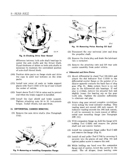
Fig, 8—Checking! ?'srwe G-sw Runout<br />
57x19<br />
difference between both axle shaft bearings to<br />
center the axle shafts and the thrust block.<br />
Equal thickness of shims on both axle shafts is<br />
necessary to maintain the centralized position<br />
of axle shaft thrust block.<br />
(10) Position shim packs on flange studs and drive<br />
the cups in until tool bottoms on the shim<br />
packs.<br />
(11) Inst<strong>all</strong> new outer oil seals on brake support<br />
plates with Tool C-3565 with lip of seal toward<br />
the center of vehicle.<br />
(12) Insert sleeve Tool C-745 in outer seal to protect<br />
seal when the brake support is inst<strong>all</strong>ed.<br />
(13) Inst<strong>all</strong> the dust shield and brake support.<br />
Tighten attaching nuts 30 to 35 foot-pounds<br />
torque. Inst<strong>all</strong> wheels, hub and drum.<br />
12. DIFFERENTIAL CAR1IER REMOVAL<br />
(1) Remove the axle drive shafts (See Paragraph<br />
11A).<br />
FLANGE<br />
L<br />
TOOL-<br />
Fig. 9—Removing or Inst<strong>all</strong>ing Companion Flange<br />
TC.<br />
IHiii<br />
57x6<br />
Fig. 10—Removing Pinion Bearing Oil Seal<br />
(2) Disconnect the rear universal joint and drop<br />
the propeller shaft.<br />
(3) Remove the drain plug and drain the lubricant<br />
into a container.<br />
(4) Remove the attaching nuts and lift rear axle<br />
carrier assembly from under vehicle.<br />
a.* Differential and Drive Pinion<br />
(1) Mount differential in stand Tool DD-1014 and<br />
attach the dial indicator Tool C-3339 to the<br />
differential carrier flange so the pointer of indicator<br />
squarely contacts the back face of ring<br />
gear (Fig. 8). Make certain there is no end<br />
play in the differential side bearings. If end<br />
play is evident, remove the adjuster lock and<br />
slightly loosen the bearing cap on the gear<br />
tooth side. Tighten the adjuster sufficiently<br />
to eliminate end play.<br />
(2) Rotate ring gear several complete revolutions<br />
while noting the total indicator reading. This<br />
reading must not exceed .005 inch runout. If<br />
indicator reading exceeds the .005 inch runout,<br />
it will be necessary to check runout of differential<br />
case mounting flange (see Paragraph<br />
12R [3]).<br />
(3) With companion flange up, hold the flange with<br />
holding Tool C-3281 and remove the pinion<br />
shaft nut and convex washer.<br />
(4) Inst<strong>all</strong> the companion flange puller Tool C-452<br />
and remove the flange (Fig. 9).<br />
(5) Inst<strong>all</strong> oil seal puller Tool C-748 by screwing it<br />
securely into the pinion oil seal (Fig. 10) and<br />
tighten puller screw to remove the seal.<br />
(6) While holding one hand over the companion<br />
flange end of carrier, invert the carrier in the<br />
stand. The oil slinger, front bearing cone