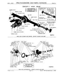
Group 3 - Rear Axle - Copyright © jholst.net, all rights reserved.
Group 3 - Rear Axle - Copyright © jholst.net, all rights reserved.
Group 3 - Rear Axle - Copyright © jholst.net, all rights reserved.

You also want an ePaper? Increase the reach of your titles
YUMPU automatically turns print PDFs into web optimized ePapers that Google loves.
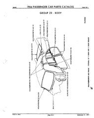
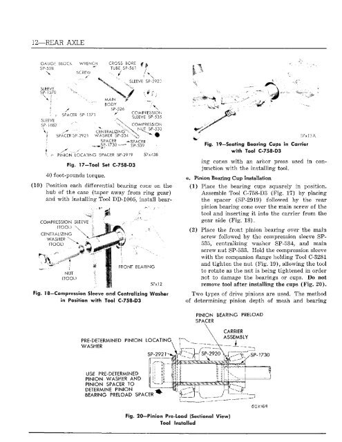
12—REAR AXLE<br />
GAUGE BLOC<br />
SP-528<br />
\<br />
SLEEVE<br />
SP-1370<br />
SLEEVE<br />
SP-V582<br />
\<br />
WRENCH<br />
SCREW<br />
SPACER SP-137:<br />
SPACER SP-2921<br />
CROSS BORS<br />
TUBE SP-561<br />
J<br />
MAIN<br />
BODY<br />
SP-526<br />
CENTRALIZING<br />
WASHER SP-534<br />
SPACER -SPACER<br />
,,SP-1730 SP-539<br />
SLEEVE SP-2920<br />
\<br />
COMPRESSION<br />
SLEEVE SP-535<br />
COMPRESSION<br />
NUT SP-533<br />
PINION LOCATING SPACER SP-2919 57x438<br />
Fig. 17-Tool Set C-758-D3<br />
40 foot-pounds torque.<br />
(10) Position each differential bearing cone on the<br />
hub of the case (taper away from ring gear)<br />
and with inst<strong>all</strong>ing Tool DD-1005, inst<strong>all</strong> bear-<br />
COMPRESSION SLEEVE<br />
(TOOL) \<br />
CENTRALIZING \<br />
WASHER \<br />
(TOOL)<br />
m<br />
NUT<br />
(TOOL)<br />
X<br />
FRONT BEARING<br />
57x12<br />
Fig. 18—Compression Sleeve < 3ntralizing Washer<br />
in Position with 1 -758-D3<br />
PRE-DETERMINED PINION LOCATING,<br />
WASHER<br />
USE PRE-DETERMINED<br />
PINION WASHER AND<br />
PINION SPACER TO<br />
DETERMINE PINION<br />
BEARING PRELOAD SPACER<br />
SP-2921<br />
57x!3A<br />
Fig. 19—Seating Bearing Cups in Carrier<br />
with Tool C-758-D3<br />
ing cones with an arbor press used in conjunction<br />
with the Inst<strong>all</strong>ing tool.<br />
e. Pinion Bearing Cup Inst<strong>all</strong>ation<br />
(1) Place the bearing cups squarely in position.<br />
Assemble Tool C-758-D3 (Fig. 17) by placing<br />
the spacer (SP-2919) followed by the rear<br />
pinion bearing cone over the main screw of the<br />
tool and inserting it into the carrier from the<br />
gear side (Fig. 18).<br />
(2) Place the front pinion bearing over the main<br />
screw followed by the compression sleeve SP-<br />
535, centralizing washer SP-534, and main<br />
screw nut SP-533. Hold the compression sleeve<br />
with the companion flange holding Tool C-3281<br />
and tighten the nut (Fig. 19), <strong>all</strong>owing the tool<br />
to rotate as the nut is being tightened in order<br />
not to damage the bearings or cups. Do not<br />
remove tool after inst<strong>all</strong>ing the cups (Fig. 20).<br />
Two types of drive pinions are used. The method<br />
of determining pinion depth of mesh and bearing<br />
PINION BEARING PRELOAD<br />
SPACER<br />
Fig. 20—Pinion Pre-load (Sectional View)<br />
Tool Inst<strong>all</strong>ed<br />
CARRIER<br />
ASSEMBLY<br />
SP-1730<br />
(50X163