pellets boiler - Paul Künzel GmbH & Co.
pellets boiler - Paul Künzel GmbH & Co.
pellets boiler - Paul Künzel GmbH & Co.

Create successful ePaper yourself
Turn your PDF publications into a flip-book with our unique Google optimized e-Paper software.
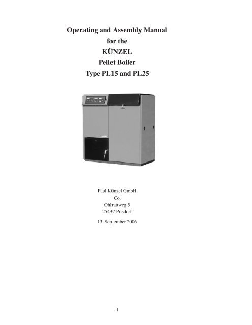
Operating and Assembly Manual<br />
for the<br />
KÜNZEL<br />
Pellet Boiler<br />
Type PL15 and PL25<br />
<strong>Paul</strong> <strong>Künzel</strong> <strong>GmbH</strong><br />
<strong>Co</strong>.<br />
Ohlrattweg 5<br />
25497 Prisdorf<br />
13. September 2006<br />
1
Inhaltsverzeichnis<br />
1 Operating Instructions for the Pellet Boiler 4<br />
1.1 Delivery ........................................... 4<br />
1.2 Accessories ......................................... 4<br />
1.3 Installation Directions .................................... 4<br />
1.4 Assembly .......................................... 5<br />
1.5 The Boiler Back–End Protection .............................. 5<br />
1.6 The Identification Plate ................................... 5<br />
1.7 Setting Up .......................................... 5<br />
1.8 Separating the Boiler from the Integrated Pellet Bin .................... 6<br />
1.9 Chimney <strong>Co</strong>nnection .................................... 7<br />
1.10 Heating <strong>Co</strong>nnection ..................................... 7<br />
1.11 Assembly of the Ventilator ................................. 8<br />
1.12 Assembly of the <strong>Co</strong>ntrol Panel ............................... 9<br />
1.13 Electric Heating Cartridge ................................. 10<br />
1.14 External Feeding of the Pellets ............................... 11<br />
1.15 Fixing the Pellet Storage Bin ................................ 12<br />
1.16 PL 25 ............................................ 12<br />
1.17 Operation .......................................... 13<br />
1.17.1 Operation without Heating Electronics ....................... 15<br />
1.17.2 Operation with Heating Electronics ........................ 15<br />
1.17.3 Operation with Buffer Storage ........................... 16<br />
1.18 Maintenance and Service .................................. 16<br />
1.18.1 Monthly Cleaning ................................. 17<br />
1.18.2 Additional Half–Yearly Cleaning ......................... 21<br />
1.18.3 Ventilator ...................................... 23<br />
2 The KUENZEL Thermomix Valve 24<br />
2.1 Legend to the Plans ..................................... 26<br />
3 System Suggestions for the PL 27<br />
3.1 Package PL1 for Pellet Boilers with Hot Water Tank .................... 27<br />
3.1.1 Hydraulic–Plan ................................... 27<br />
3.1.2 Electro–Plan .................................... 28<br />
3.2 Package PL2 for Pellet Boilers with Hot Water Tank and Buffer Storage ......... 28<br />
3.2.1 Hydraulic–Plan ................................... 29<br />
3.2.2 Electro–Plan .................................... 29<br />
3.3 Package PL3 for Pellet Boilers with a <strong>Co</strong>mbi–Tank .................... 29<br />
3.3.1 Hydraulic–Plan ................................... 30<br />
3.3.2 Electro–Plan .................................... 30<br />
4 <strong>Co</strong>nnection Box for the Heating Electronics Type Theta 31<br />
4.1 Assembly .......................................... 31<br />
3
1 Operating Instructions for the Pellet Boiler<br />
1.1 Delivery<br />
The KUENZEL Pellet Boiler is sealed in environmentally–friendly PE foil and is delivered on disposable<br />
pallets with an enclosed control panel and ventilator.<br />
1.2 Accessories<br />
Enclosed with the pellet <strong>boiler</strong> are:<br />
1 guarantee card<br />
1 cleaning brush<br />
15 kg <strong>pellets</strong><br />
1.3 Installation Directions<br />
This pellet <strong>boiler</strong> has been approved for operation with an open or closed heating system with an allowed<br />
operational pressure of a maximum 3 bar and a maximum flow temperature of 95◦ C.<br />
The pellet <strong>boiler</strong> must not be operated without the <strong>boiler</strong> back end protection. The function of the <strong>boiler</strong><br />
back–end protection should be supervised. With systems without a buffer storage, a 4–way mixer is<br />
sufficient as the <strong>boiler</strong> back–end protection.<br />
This pellet <strong>boiler</strong> must only be operated with fuel according to the German norm BImSchV figure 5a<br />
(using wooden <strong>pellets</strong> made of natural untreated wood). (This <strong>boiler</strong> corresponds to the German official<br />
acts for operating <strong>boiler</strong>s as well as to the DIN EN 303–5). (DIN stands for Deutsche Industrie Norm<br />
which means the German Industry Norm)<br />
Only <strong>pellets</strong> with a diameter of 6mm or 8mm are permitted. The <strong>pellets</strong> must correspond to the standard<br />
of the DIN Plus or of the PVA (Pellets Association Austria). Other fuels, especially <strong>pellets</strong> which contain<br />
recycled material, must not be used.<br />
Please be aware that the DIN 51731 <strong>pellets</strong> can have a higher proportion of ash and a minor non–<br />
abrasiveness than the PVA or DIN Plus <strong>pellets</strong>. The minor non–abrasiveness can cause a considerably<br />
high proportion of dust which may lead to failure of the screw conveyor. DIN 51731 <strong>pellets</strong> are, as a rule,<br />
not suitable for operation in the pellet <strong>boiler</strong> due to their bad material properties.<br />
The details of the cleaning schedule refers to the PVA <strong>pellets</strong>. When other <strong>pellets</strong> are used, a more<br />
frequent cleaning might be required, as there is a danger of a heavy slag build–up in the burner.<br />
In the interests of operation safety, it is not advisable to put in other fuels than DIN–Plus or PVA–<br />
Standard <strong>pellets</strong>!<br />
Do not fill the <strong>boiler</strong> with shavings or dust.<br />
–Danger of explosion–<br />
All KUENZEL products are subject to technical alterations. KUENZEL assumes no liability for functional<br />
problems due to using component parts which are no KUENZEL products. This refers especially to<br />
control devices of other makes. KUENZEL assumes no liability either in case of operating problems due<br />
to on–site conditions like the hydraulic system, exhaust gas system or external conveyor technique.<br />
4
1.4 Assembly<br />
The KUENZEL Pellet Boiler is type–examination tested (DIN K 2106/90) and complies with the<br />
BImSchV of Oktober 1988.<br />
Before the pellet <strong>boiler</strong> is assembled, the approval of the appropriate chimney sweep service must be<br />
obtained. Please check if building permission is required. The assembly of the <strong>boiler</strong> must only be carried<br />
out by an authorized heating technician. In the same way, the electrical connections must be carried out<br />
by an authorized electrician. An leakage current protection–switch should be supplied. In the <strong>boiler</strong>,<br />
only heat–resistant silicone cables should be fitted! Do not use PVC cables.<br />
The relevant norms and official building regulations should be complied with.<br />
Advice regarding the assembly and service of the control panel are to be found in the control panel<br />
operation instructions manual.<br />
1.5 The Boiler Back–End Protection<br />
This pellet <strong>boiler</strong> must only be operated with a <strong>boiler</strong> back–end protection. In systems without buffer<br />
storage and with little water volume, a 4–way mixer is sufficient. For systems with buffer storage or with<br />
a large water volume, the KUENZEL Thermomix Valve (article no. 150218) is required.<br />
1.6 The Identification Plate<br />
Abbildung 1: Identification plate and factory number<br />
If you have any questions or complaints about your <strong>boiler</strong>, please always quote the 6–digit factory number.<br />
This number is on the identification plate.<br />
The identification plate is to be found behind the ash door.<br />
1.7 Setting Up<br />
The KUENZEL Pellet Boiler PL is delivered on a transport pallet. Due to its compact shape, it is possible<br />
to bring it into the <strong>boiler</strong> room through a 750mm wide door opening. Advice: For easier transport, the<br />
5
Abbildung 2: Boiler and integrated pellet storage bin are transported separately<br />
integrated pellet storage bin is detachable. In this way, it is also possible to carry the <strong>boiler</strong> down narrow<br />
cellar steps.<br />
When setting up, the local regulations and guidelines regarding installation in <strong>boiler</strong> rooms should be<br />
observed.<br />
Setting up the pellet <strong>boiler</strong> and the pellet storage must only take place in a dry, frost–proof authorized<br />
room. A sufficient ventilation regulation in the <strong>boiler</strong> room has to be made sure.<br />
For setting up the <strong>boiler</strong>, a level and adequately load–bearing floor is sufficient. If, however, a pedestal<br />
has to be used, it should be the same size or slightly bigger than the <strong>boiler</strong> itself.<br />
1.8 Separating the Boiler from the Integrated Pellet Bin<br />
So that the KUENZEL Pellet Boiler can be carried more easily into rooms which are difficult to access,<br />
one can separate the main body of the <strong>boiler</strong> from the pellet storage bin. This job can only be carried out<br />
by two men.<br />
To separate the integrated pellet bin from the <strong>boiler</strong>, these guidelines are to be followed:<br />
1. Loosen the pellet supply flange screws as shown in the picture and put them aside.3 auf Seite 7<br />
2. Loosen the screws at the four points of attachment as portrayed in picture ?? auf Seite ?? and put<br />
them aside.<br />
3. Now lower the pellet bin carefully from the flange.<br />
6
Abbildung 3: Flange screws in pellet bin<br />
In order to carry the main body of the <strong>boiler</strong>, there are two points of attachment on the right and left sides<br />
of the <strong>boiler</strong> into which 1“ pipe ends can be screwed.<br />
Now, the body of the <strong>boiler</strong> is able to be carried.<br />
1.9 Chimney <strong>Co</strong>nnection<br />
The KUENZEL pellet <strong>boiler</strong> is equipped with an exhaust gas ventilator. The ventilator can be fitted with<br />
the exhaust gas escape which can point optionally to the right, to the left or in an upward direction. An<br />
exhaust gas escape pointing downwards is not permissable.<br />
The exhaust pipe to the chimney should be short, without any extra bends if possible and fixed in an<br />
upward direction. When inserting it into the chimney, it should be rounded off at the top and fitted into a<br />
position which allows the draught current to flow through well.<br />
For any important information regarding the chimney calculations please refer to the technical data in<br />
chapter ?? auf Seite ??. To use a chimney which has a smaller diameter than the smoke ducts is not<br />
permissable.<br />
Caution: Please be aware that with the low exhaust temperatures occuring constantly whilst in operation,<br />
a damp–resistant fireplace (heat–flow number and resistance group I of the type DIN 18160/T1) may be<br />
required.<br />
If the <strong>boiler</strong> has to be connected to an already existing chimney, the dimensions of the chimney must<br />
be calculated / a chimney report must be done beforehand. The agreement of your local chimney sweep<br />
service must be obtained before installation.<br />
Due to the ventilator, disruptive noises can occur at the chimney. For this reason, we recommend that the<br />
connection should be made with a flexible exhaust gas pipe input into the chimney.<br />
Make sure that the exhaust gas pipe has been tested to be free of leaks, as otherwise exhaust fumes could<br />
escape into the <strong>boiler</strong> room. This applies especially to the cleaning openings at the bends in the pipe.<br />
1.10 Heating <strong>Co</strong>nnection<br />
In order to avoid operational disruptions, we recommend to you that the heating connection should be<br />
formed according to one of the published KUENZEL system packages. For this, please note chapter3<br />
7
auf Seite 27.<br />
Abbildung 4: The 4 places of attachment<br />
The connection of the flow and return must be set up so that they cross each other, in order to avoid a<br />
short–circuit of the current. Caution: When choosing the flow connecting pieces, pay attention to the<br />
fitted position of the ventilator! If the ventilator has been assembled with the exhaust gas escape pointing<br />
to the right, the right flow connecting pieces would be hidden and, therefore, would be unable to be used.<br />
1.11 Assembly of the Ventilator<br />
The ventilator is fitted to the exhaust gas excape nozzle on the rear side of the <strong>boiler</strong>. Push the ventilator<br />
onto the nozzle. The fan can then be turned so that the exhaust gas escape can be optionally positioned<br />
facing the right, left, the top or bottom.<br />
Now assemble the smoke pipe and adjust the exhaust gas facility. Then the ventilator should be fixed to<br />
the nozzle with the three clamp–screws.<br />
You must make sure that the exhaust gas system is leak–proof, as otherwise under bad conditions<br />
smoke gas could escape!<br />
Make sure that the space where the flue–pipe is, between the ventilator and the chimney, can still be<br />
reached for cleaning purposes.<br />
8
1.12 Assembly of the <strong>Co</strong>ntrol Panel<br />
Abbildung 5: Exhaust gas ventilator<br />
Abbildung 6: Assembling control panel<br />
The service instructions of the <strong>Co</strong>ntrol Panel 806 need to be read as they contain the directions for<br />
attaching the screws. If further information about this is required, the screw attachment instructions are<br />
additionally described on the back of the control panel.<br />
Enclosed with the <strong>Co</strong>ntrol Panel 806 are also two buffer sensors (6 metres long) and a <strong>boiler</strong> sensor,<br />
which are to be found next to an operation instructions manual and a plastic bag with all the necessary<br />
plugs in it. If the <strong>boiler</strong> is operated on a heating system with buffer storage, the buffer sensors must<br />
be connected. To do this, please pay attention to the guidelines in the control panel manual. If a buffer<br />
storage is not installed, then the connection of the buffer sensors cannot be made.<br />
The <strong>boiler</strong> sensor should now be inserted into the middle immersion case of the <strong>boiler</strong> and connected to<br />
the appropriate place on the sensor plug.<br />
The left immersion case is reserved for the <strong>boiler</strong> sensor of the optional weather–responsive heating<br />
electronics.<br />
The cables for the vacuum sensor, for contact switch of the pellet bin flap and for the exhaust gas sensor<br />
are also connected to the sensor plugs of the 806–control panel. If the heating electronics are inserted, the<br />
9
Abbildung 7: <strong>Co</strong>ntrol panel 806 with weather–responsive heating electronics (optional) and safety temperature<br />
limiter<br />
evaluation cable for the burner must be connected additionally to the bottom sensor plug. Details about<br />
this can be found in the connection box manual.<br />
The cables for the ventilator, the electronic fuse and the conveyor screw will have been fitted into the<br />
<strong>boiler</strong>. The cables for the components which need to be fitted by client, such as those for mains connection<br />
or for the <strong>boiler</strong> circulation pump, must be fitted into the <strong>boiler</strong> by a qualified electrician. For this purpose,<br />
there is a little channel for the cables on the left side of the <strong>boiler</strong>. The cable for the ventilator will have<br />
already been fitted through this channel.<br />
Now insert all plugs into their appropriate places on the control panel.<br />
The control panel should then be pushed into place until it is safely secured on its little pins.<br />
1.13 Electric Heating Cartridge<br />
If requested, the KUENZEL <strong>boiler</strong> can be equipped with an electric heating cartridge (article no. 150246)<br />
for frost protection. For the connection of this electric heating cartridge, a connection for strong currents<br />
(3x 400 volts 16 amps) should be inserted.<br />
The electric heating cartridge can also be operated with 230volt 25 amps. For this, the wiring of the<br />
cartridge should be changed according to the details of the manufacturer. Caution: These tasks must<br />
only be carried out by a qualified electrician. Please consult the enclosed electric heating cartridge<br />
instructions manual if you want to find out the exact wiring plan.<br />
On the back of the <strong>boiler</strong>, there is a two inches socket, into which the electric heating cartridge can be<br />
inserted.<br />
The electric heating cartridge has its own thermostats. This thermostat can be adjusted to a variable<br />
temperature between 5oC and 75oC. If the electric heating cartridge only has the function of a frost<br />
guard, it is sufficient to adjust the thermostats by turning the control to the left (5o C).<br />
In order to avoid switching on the electric heating cartridge unintentionally, the contact for the secondary<br />
heating can also be used. The electric heating cartridge cannot be, however, switched on or off directly<br />
by using this. An in–between relay is always required. Important: This also applies to the connection<br />
with 230 volts!<br />
10
Abbildung 8: Plan of connections for PL with ext. conveyor screw for 400V motor<br />
1.14 External Feeding of the Pellets<br />
The pellet <strong>boiler</strong> is equipped with a large integrated pellet storage bin. The pellet bin fill–up by hand<br />
is standard, but the <strong>boiler</strong> is also optionally equipped with an automatic, external pellet feeding facility.<br />
The control of this external feeding of <strong>pellets</strong> is done by the <strong>Co</strong>ntrol Panel 806. The following additional<br />
articles will definitely be needed for an external feeding:<br />
Feeder fittings for the pellet storage bin (type no. 100050)<br />
Full–registration for the pellet storage bin (type no. 100051)<br />
Motor connection set for a 400 volt three–phase motor (type no. 100052)<br />
We can offer you different hopper–systems and conveyor screws suitable for solidly built pellet storage<br />
rooms. Further information about this can be found in the <strong>boiler</strong> planning folder or in our price list.<br />
The external pellet bin feeding of the <strong>Co</strong>ntrol Panel 806 can be started at any given point in time by<br />
the operator (e.g. 15:00). The feeding runs until the bin is full or until the programmed filling up time<br />
has run out. Make a note of how long the feeding facility takes until the bin is completely full i.e. to its<br />
maximum registration. Then adjust the maximum filling time to approx. 5 minutes longer than the actual<br />
filling time.<br />
The filling of the pellet bin is now automatically repeated every 24 hours by the control panel. Depending<br />
on the motor type used, the electrical connection is made according to plan8 auf Seite 11 or according<br />
to plan 9 auf Seite 12.<br />
11
Abbildung 9: Plan of connections for PL with ext. conveyor screw for 240V motor<br />
Important: For 400 volt three–phase motors, the KUENZEL motor connection set of the type no.<br />
100052 is recommended. If the motor connection has already been fitted, it is advisable to use the corresponding<br />
motor protection–switch.<br />
Attention: Take care that there evolves no vaccum in the pellet bin when the external pellet storage<br />
is beeing filled. You can avoid this by simply opening the flap of the pellet bin. Before having the external<br />
storage room filled switch off the KUENZEL pellet <strong>boiler</strong>. To do this, press the START/STOP<br />
button to produce a burn–out and make sure there are no glowing or burning <strong>pellets</strong> left in the fire<br />
pan or on the ash–tray. Filling up the external storage room must take place under observation<br />
only!<br />
1.15 Fixing the Pellet Storage Bin<br />
For safety reasons, the lid of the pellet bin must always be kept closed during operation . If the flap<br />
opens, the conveyor screw will stop and the caution symbol on the control panel will light up. If the flap<br />
is closed again, the lighted symbol will disappear and operation will resume.<br />
Please always be aware that the the pellet bin lid closes well. If the locking screw is getting loose, it must<br />
be tightened again.<br />
1.16 PL 25<br />
If you have a PL25 <strong>boiler</strong>, please check if all 14 of the turbo– gratings are hanging correctly in place in<br />
the heat exchanger before starting it for the first time.<br />
12
Abbildung 10: Cleaning lid of the heat exchanger<br />
Abbildung 11: Heat exchanger with turbo–gratings and operating lever<br />
Open the cleaning lid of the heat exchanger and check if all turbo–gratings are in place. Caution: The<br />
turbo–gratings can have sharp edges and, therefore, protective gloves should be worn.<br />
With the PL25, the turbo gratings are linked to the ash–removing lever of the baffle plate. If the appropriate<br />
lever on the left side of the <strong>boiler</strong> is activated, the turbulators will move up and down. This action<br />
cleans the heat exchanger. The cleaning procedures, as described in chapter fullrefpc1 would, therefore,<br />
be unnecessary.<br />
1.17 Operation<br />
1. <strong>Co</strong>nveyor screw motor<br />
2. Plug for the conveyor screw motor<br />
3. Emptying lid for the pellet bin<br />
4. Vacuum sensor<br />
5. Burner drawer with automatic de–ashing of the fire pan<br />
13
6. Fuse box<br />
7. Downpipe for the <strong>pellets</strong><br />
8. Burner pipe<br />
9. Main pipe for the fuse cable<br />
Abbildung 12: Pellet <strong>boiler</strong><br />
Abbildung 13: Overview of the PL15 mechanism<br />
If the <strong>boiler</strong> has been fully connected to the heating system with both water and electricity supplies, the<br />
PL can be operated.<br />
At first, the pellet bin must be filled up. The filling is done by hand. We recommend that the bin should<br />
always be filled up to the top to ensure a good, long operation.<br />
The filling up of the pellet storage bin can also be done automatically with the aid of an optional external<br />
feeding facility. Further information about his can be found in our material.<br />
Important: The KUENZEL pellet <strong>boiler</strong> is equipped with an automatic fire pan ash–emptier. The ash–<br />
emptying cycle is introduced after each burn–out. If there’s no burn–out for a certain amount of time, the<br />
14
control panel will induce a burn–out and, in turn, an ash–emptying cycle will start. Further details about<br />
this can be found in the control panel instructions manual.<br />
When the pellet storage bin has been filled with fuel, the <strong>boiler</strong> can be operated. There are two different<br />
basic modes of operation:<br />
1.17.1 Operation without Heating Electronics<br />
In the standard version, the PL is operated without weather–responsive heating electronics. In order<br />
to set the <strong>boiler</strong> in operation, the control panel is switched on at the ON/OFF switch. Then the <strong>boiler</strong><br />
begins with the ignition. The remaining minutes of the ignition period appears in the left–hand segment<br />
of the display. The ignition process finishes either at the end of the ignition period or when the control<br />
panel has recognized that the <strong>pellets</strong> have definitely been ignited due to a sudden rise in the exhaust gas<br />
temperature.<br />
The PL should now run at full load operation until the <strong>boiler</strong> reaches a temperature 10 K (you can choose<br />
a value between 30 K and 10 K) below the pre–set <strong>boiler</strong> target temperature. If this happens, the PL<br />
will switch itself automatically to partial load operation. If the <strong>boiler</strong> temperature decreases under the<br />
threshold value again, the PL will switch itself back onto full power.<br />
Should the <strong>boiler</strong> exceed the pre–set <strong>boiler</strong> target temperature, despite the <strong>boiler</strong> being in partial load<br />
operation, the burner switches itself off. In the left segment of the display, the letter „A“appears. If the<br />
exhaust gas temperature falls under 90◦ C, the letter „E“appears in the display. The pellet <strong>boiler</strong> now goes<br />
through an automatic fire pan ash–emptying cycle. As soon as the temperature sinks under the adjustable<br />
switch-on temperature (pre–set by factory onto 70o C) again, the burner starts automatically and the work<br />
cycle begins again.<br />
If the PL shall be stopped, the START button must be pressed again until the letter „A“appears in the left<br />
segment of the display.<br />
The <strong>boiler</strong> target temperature can be set between 80o C and 87oC. The long hysteresis between the points<br />
of turning on and off ensures that the burner runs for a long time. This ensures that the operation runs<br />
more economically and with low emissions.<br />
1.17.2 Operation with Heating Electronics<br />
A PL can be optionally equipped with weather–regulated heating electronics from KUENZEL. It should<br />
also be noted that the connection box of the type no. 150252 is compulsory for the operation with<br />
weather–influenced heating electronics. Caution: A cable must be fitted by client from the connection<br />
box to the burner point of contact on the 806–control panel. The clamps 1 and 2 of the connection<br />
box should be connected to the clamps 3 and 4 of the bottom sensor plugs on the 806.<br />
In order to ensure that operation runs in the best possible way, the steepness of heating characteristics of<br />
the <strong>boiler</strong> circulation should be set to 2.5, the burner–switch difference to 10 K, the minimum running<br />
time of the burner to 10 minutes and the <strong>boiler</strong> maximum temperature to 85o C. The <strong>boiler</strong> and the tank<br />
start relief are switched on. These jobs are only allowed to be carried out by a heating technician.<br />
To reassure that the <strong>Co</strong>ntrol Panel 806 recognises the heating electronics correctly, move the DIP–switch<br />
on the back of the control panel into the position „heating electronics“˙To do this, read also the appropriate<br />
chapter in the control panel manual.<br />
In order to set the <strong>boiler</strong> in operation, the control panel should be switched on using the ON/OFF switch.<br />
Then the START–button should be pressed. If now the heating electronics request heat from the burner,<br />
15
the PL begins the ignition. The remaining ignition time in minutes appears in the left segment of the<br />
display. The ignition process finishes either at the end of the ignition time or when the control panel, due<br />
to a sudden rise in the exhaust gas temperature, has recognized that the <strong>pellets</strong> have already been ignited.<br />
The PL now runs at full <strong>boiler</strong> power until the <strong>boiler</strong> reaches a temperature 10 K (adjustable between 30<br />
K and 10 K) below the pre–set <strong>boiler</strong> target temperature. If this happens, then the PL switches itself into<br />
partial load operation automatically. If the <strong>boiler</strong> temperature drops under the threshold value again, then<br />
the PL switches itself back onto full power again.<br />
The PL remains in operation until the heating electronics demand no more heat from the burner. In the<br />
left segment of the display, the letter „A“appears. If the exhaust gas temperature falls below 90◦ C, the<br />
letter „E“appears in the display. The pellet <strong>boiler</strong> then passes through an automatic fire pan ash–emptying<br />
cycle. If the heating electronics request heat from the burner again, the PL starts once more.<br />
We recommend the KUENZEL weather–regulated heating electronics for all heating systems, in which<br />
the PL functions as the single source of heat.<br />
1.17.3 Operation with Buffer Storage<br />
The PL can also be operated with buffer storage. We recommend the operation with buffer storage as it<br />
enables a longer running time of the burner, as well if only little heat is demanded. This way emissions<br />
and the general wear and tear can be reduced.<br />
If the buffer storage is integrated into the system, the two buffer sensors have to be joined to the 806 <strong>Co</strong>ntrol<br />
Panel and assessed. The <strong>boiler</strong> can, as described above, be started. There are two possible operation<br />
modes:<br />
Operation without heating electronics The <strong>boiler</strong> stays in operation until the <strong>boiler</strong> temperature exceeds<br />
the <strong>boiler</strong> target temperature. Now a burn-out begins. As soon as the exhaust gas temperature falls<br />
below 90◦C the buffer temperature will be controlled. If now the upper buffer temperature is higher than<br />
the set switch-over temperature, the <strong>boiler</strong> circulation pump stops. The upper buffer temperature has to<br />
fall below the switch-over temperature, before the <strong>boiler</strong> circulation pump starts again. The burner will<br />
stay blocked as well until the upper buffer temperature falls below the switch-over temperature, even if<br />
the <strong>boiler</strong> temperature falls below 70◦C. Operation with heating electronics If there is a request of the heating electronics on the burner, the<br />
<strong>boiler</strong> circulation pump is switched on. If the heating electronics’ request stops, the <strong>boiler</strong> circulation<br />
pump keeps on working until a burn-out starts. If the <strong>boiler</strong> reaches a temperature 2◦ C (adjustable) above<br />
the lower buffer temperature, the <strong>boiler</strong> circulation pump stops. The <strong>boiler</strong> circulation pump starts again,<br />
if the <strong>boiler</strong> reaches a temperature 2◦C (adjustable) below the upper buffer temperature or if the heating<br />
electronics send a new request.<br />
1.18 Maintenance and Service<br />
As with all technical appliances, your pellet <strong>boiler</strong> must be regularly checked and serviced. Depending<br />
on the cleaning function, the different cleaning intervals should be kept. An additional thorough service<br />
should be carried out before long periods of disuse such as before the summer holidays.<br />
We recommend that you arrange a service contract with your heating technician.<br />
16
1.18.1 Monthly Cleaning<br />
Abbildung 14: Taking out the burner drawer<br />
Once a month, the ashtray has to be emptied. To do this, switch off the <strong>boiler</strong> by pressing the<br />
START/STOP button on your control panel and then wait until the <strong>boiler</strong> reaches the state of burn–<br />
out. Now the ash–door can be opened and the ashtray taken out. Be aware that the hot ash should not be<br />
put into a container which is either made of flammable material or contains flammable material in it.<br />
The fire pan must also be checked at least once a month to ensure that it runs smoothly and reliably.<br />
When the <strong>boiler</strong> is switched off, open the ash–door. Then disconnect the fuse–cable plug and the plug<br />
for the ash–emptying motor and put the pipe for the cable towards the front so that it is out of the way.<br />
The burner drawer [12] with the fire pan [13] can then be pulled in a forward direction and then removed<br />
from the <strong>boiler</strong>.<br />
Caution: Around the burner–drawer, there could still be hot or glowing traces of ash. So, only put the<br />
burner–drawer on top of a fire–proof surface.<br />
Next, the fire pan can be taken out of the burner–drawer with a slight lift in a backwards direction.<br />
Then remove all traces of ash from the fire pan and from the bottom of the drawer. All holes in the fire<br />
pan must also be free of ash traces. Likewise, any ash in the fuse–pipe should also be removed. [14].<br />
Move the burner–drawer and check the boost–link [16] and the area [17] at the drawer[15]. Any stuck<br />
ash also needs to be removed.<br />
After the thorough cleaning, the fire pan is put back into the burner–drawer. Be careful that the fuse–pipe<br />
is put back into the appropriate hole in the fire pan. The fuse–pipe should be pushed that far into the fire<br />
pan that 1mm to 2mm is showing.<br />
Now push the burner–drawer back into its place. Make sure that the drawer is pushed in properly until<br />
its end position.<br />
The pipe for the cables needs to be put back into place and the plugs reconnected.<br />
17
Abbildung 15: Fitting position of the fire pan<br />
Abbildung 16: Taking out the fire pan<br />
18
Abbildung 17: Drawer bottom of the fire pan ash–emptier<br />
Abbildung 18: Heat exchanger with turbo–gratings and operating lever<br />
19
Abbildung 19: Operating lever for the heat exchanger cleaning<br />
20
1.18.2 Additional Half–Yearly Cleaning<br />
Abbildung 20: Heat exchanger with turbo gratings and dust catch (middle). Exhaust gas sensor above<br />
right<br />
Abbildung 21: Burner pipe with overlay<br />
In order to guarantee a constant and reliable function of your pellet <strong>boiler</strong>, it is necessary to clean the<br />
ventilator. To do this, please read chapter 1.18.3 auf Seite 23.<br />
To maintain the PL’s high level of efficiency, the flue gas ducts must also be cleaned. To do this, take off<br />
the red top casing behind the control panel and then open the cleaning hatch which lies underneath it.<br />
Now the flue gas ducts and the upper dust catch are visible. The dust catch can be cleaned with a vacuum<br />
cleaner. Make sure, though, that the exhaust gas sensors do not become damaged or pushed out of place.<br />
With the PL25, a manual cleaning of the heat exchanger is not necessary.<br />
The flue gas ducts can be cleaned thoroughly using the cleaning brush. It may be necessary for the dust<br />
catch to be vacuumed once again after the flue gas ducts have been cleaned. Finally, the cleaning lid and<br />
the red casing can be closed again.<br />
Then push down the appropriate lever on the left side of the <strong>boiler</strong> in order to clean the baffle–plate.<br />
For removing all traces of ash from the <strong>boiler</strong> which were scattered when the flue gas ducts were cleaned,<br />
21
Abbildung 22: Disassembly of the fuse box<br />
Abbildung 23: Fuse<br />
open the ash–door and take out the burner–drawer, as described in chapter1.18.1 auf Seite 17.<br />
Next, lift the burner–pipe [8] carefully, pull it to the left and then remove it from the <strong>boiler</strong>.<br />
Subsequently, the end–piece of the down–pipe [7] should be taken out of the <strong>boiler</strong>. To do this, the<br />
tightening screw needs to be loosened. The end–piece can now be pulled out from the down–pipe. Lift<br />
out the burner–pipe overlay [10] from its position and remove it from the <strong>boiler</strong>. Then the burner overlay<br />
[11] needs to be lifted out of place and taken out of the <strong>boiler</strong> in a forwards motion.<br />
Finally, the ashtray should be taken out of the <strong>boiler</strong>. The remaining ash can be removed from the <strong>boiler</strong><br />
with a vacuum cleaner.<br />
After a thorough cleaning around the burner area, all parts need to be reassembled in reverse order.<br />
The pellet bin should be completely emptied during its half–yearly cleaning procedures. Any existing<br />
automatic filling facilities are to be switched off. The wood–powder, which is to be found in the pellet–<br />
bin, can be removed with the pellet bin–emptier [3] or with a vacuum cleaner.<br />
During the half–yearly cleaning procedures, the fuse element must also be checked and cleaned. To do<br />
this, loosen the tightening screw of the fuse box [6] and pull it through the hole in the fire pan and then<br />
out of the burner–drawer.<br />
After the service has been completed and the fuse element cleaned, the <strong>boiler</strong> has to be reassembled in<br />
22
everse order.<br />
1.18.3 Ventilator<br />
Abbildung 24: Exhaust gas ventilator<br />
Abbildung 25: Inner view of the ventilator<br />
Caution: Before working on the ventilator, pull out the mains plug from its socket without fail!<br />
Due to the dust in the exhaust gas, the ventilator will become dirty. The dust settles on the blades of the<br />
ventilator and slows it down so that it can no longer drive the gas through adequately. Dust on the blades<br />
can also lead to run–outs. This could considerably reduce the life–span of the motor system. Therefore,<br />
the ventilator must be cleaned at least twice a year! If the ventilator produces uncustomary noises<br />
or run–outs whilst in operation and it is not yet due to be cleaned then an earlier cleaning should be<br />
arranged.<br />
For the cleaning, the ventilator can remain in place. Only the entity of motor and ventilator wheel needs<br />
to be removed from its case.<br />
To do this, disconnect the ventilator cable, loosen the screws at the motor–flange and pull out the motor<br />
with the ventilator–wheel from the case.<br />
The ventilator–wheel is now freely accessible from all sides and can be cleaned i.e. with compressed air<br />
(ventilator–wheel must be held tightly!) or with a brush. When doing so, the upcoming dust should be<br />
23
emoved with a vacuum cleaner from time to time. Do not forget to vacuum inside the ventilator case as<br />
well!<br />
After cleaning, the ventilator needs to be reassembled in reverse order.<br />
Caution: Be aware that during the first run after the cleaning, heavy dust could build up.<br />
If you have any questions or problems concerning your KUENZEL Pellet Boiler, please contact either<br />
your heating installer or your national KUENZEL agent. (See bf www.kuenzel.de).<br />
2 The KUENZEL Thermomix Valve<br />
Abbildung 26: Thermomix Valve Functions Diagram<br />
The KUENZEL Thermomix Valve is an automatic <strong>boiler</strong> back-end protection which does not require<br />
any other additional energy resources. The return-flow water, which comes out cold from the heating<br />
system, is pre-heated with hot flow-pipe water to a minumum of 63o C. This temperature is above the<br />
dew-point of the exhaust gas in the <strong>boiler</strong>, so that a build-up of condensation and premature damage of<br />
the <strong>boiler</strong> through corrosion can be avoided. The benefit of the <strong>boiler</strong> circulation pump (15) is not only<br />
for the bypass, but also as a loading facility for the buffer storage. The Thermomix Valve can be adjusted<br />
to match a <strong>boiler</strong> power of up to 50kW.<br />
<strong>Co</strong>nnections: In-put R 1 1/2“ , out-put R 1 1/2“˙A swivel-nut must fit the pump connection.<br />
Assembly: We recommend the installation with flat gaskets and stop valves at all three in-put points.<br />
This makes the service and maintenance easier because the whole system does not have to be emptied.<br />
The flaptrap of the Thermomix Valve must be kept shut when the system is being installed. If necessary,<br />
turn the inserted plastic part in the appropriate direction. Please be aware of the direction of the current!<br />
When the valve is being assembled, please use a pair of pliers.<br />
Service: Once a year, the valve must be opened up and cleaned. The expansion cartridge should be<br />
replaced after 5 years as a precautionary measure. If a fault occurs, all movable parts can be taken out<br />
using the lid at the side. This makes the cleaning and also the replacement of parts easier, as it saves<br />
having to take the whole Thermomix Valve out.<br />
24
Abbildung 27: Plan of a system with Thermomix Valve<br />
1. <strong>Co</strong>ld-start phase: Flow and Return are cold (less than 63o C). The Thermomix is open for the<br />
bypass only; the flap trap is closed and keeps the return water out.<br />
2. Mix-phase: The water from the flow is warmer than 63oC, it becomes mixed up with enough cold<br />
water from the return to raise the return temperature to 63o C.<br />
3. The return temperature is warmer than 63 o C. The bypass is shut.<br />
For the meaning of the numbers in the pictures, please refer to the key in chapter2.1 auf Seite 26<br />
25
2.1 Legend to the Plans<br />
No. Part<br />
1 HV–<strong>boiler</strong><br />
2 HV–control panel<br />
3 Oil–gas–<strong>boiler</strong><br />
4 Oil–gas–<strong>boiler</strong>–control panel<br />
5 Heating electronics<br />
6 Thermomix–Valve<br />
7 Buffer tank PS<br />
8 <strong>Co</strong>mbined buffer / hot water tank PSB<br />
10 Hot water tank HSR / TS<br />
11 Reversing valve<br />
12 Three–way–mixer<br />
13 Set of fittings<br />
14 Wall mounting box<br />
15 Boiler circulation pump<br />
16 Oil <strong>boiler</strong> pump<br />
17 Boiler sensor of the heating electronics<br />
18 Heating circuit pump<br />
19 Heating system<br />
20 Hot water tank charge pump<br />
21 Flap trap<br />
22 <strong>Co</strong>ntact thermostat<br />
23 Pedestal for the oil <strong>boiler</strong><br />
24 Supporting pump<br />
25 Instantaneous gas hot water heater<br />
26 Automix<br />
27 Hot water thermostat<br />
28 <strong>Co</strong>mbi–tank PSG<br />
29 Solid fuel <strong>boiler</strong> FO15<br />
30 Thermostat 1x change–over contact<br />
31 Solar panel<br />
32 Layer storage tank<br />
33 Solar hot water tank<br />
34 Solar control panel<br />
35 Solar station<br />
36 PL15<br />
37 Four–way–mixer<br />
38 <strong>Co</strong>ntact thermostat<br />
39 Central heating cooker<br />
40 pump / change–over control<br />
26
3 System Suggestions for the PL<br />
3.1 Package PL1 for Pellet Boilers with Hot Water Tank<br />
This suggestion for a pellet <strong>boiler</strong> heating system according tosystem package PL1, shows how to build<br />
an uncomplicated, economical and small heating installation with a regulated hot water tank.<br />
The PL may only be operated with a <strong>boiler</strong> back–end protection. The 4–way mixer [37] serves as <strong>boiler</strong><br />
back–end protection and heating mixer at the same time and also protects your <strong>boiler</strong> from corrosion.<br />
The regulation of the PL, of the hot water tank and of the 4–way mixer is done by the integrated optional<br />
heating electronics.<br />
The minimum <strong>boiler</strong> temperature delimination of the heating electronics must be set to 50o C; the burner<br />
switch–difference to 15oC. Please consult the heating electronics instructions on this subject.<br />
Before installing the system, please read the operation and assembly instructions of all appliances. Make<br />
sure that the <strong>boiler</strong> control panel feelers do not become mixed up with those of the heating electronics.<br />
The wiring of the system must only be carried out by an electrician; PVC cables must not be fitted into<br />
the <strong>boiler</strong>.<br />
The electro–connection is made after the electro–plan to the system package PL1.<br />
3.1.1 Hydraulic–Plan<br />
Abbildung 28: System Package PL1<br />
27
3.1.2 Electro–Plan<br />
Abbildung 29: Electro–plan to the package PL1<br />
3.2 Package PL2 for Pellet Boilers with Hot Water Tank and Buffer Storage<br />
This suggestion for a pellet <strong>boiler</strong> heating system according tosystem–package PL2 shows how to build<br />
an uncomplicated, economical and small pellet heating installation with regulated hot water tank and<br />
buffer storage. With this system, a 4–way mixer as <strong>boiler</strong> back–end protection is not enough. It should,<br />
therefore, be provided with a Thermomix Valve.<br />
Make sure that the <strong>boiler</strong> circulation pump (15) and the heating circuit pump (18) match up with each<br />
other correctly. Please also read the section „Fitting the <strong>boiler</strong> back–end protection“ in our technical<br />
material for this.<br />
We recommend that the Thermomix–Valve and the buffer storage are installed in such a way that they<br />
can be blocked on all sides so that an easier service is possible.<br />
The minimum <strong>boiler</strong> temperature delimination of the heating electronics must be set to 60o C; the burner–<br />
switch difference to 15oC. Please read the heating electronics instructions to do this.<br />
Before installing the system, please read the operation and assembly instructions of all appliances to<br />
make sure that the <strong>boiler</strong> control panel sensors do not become mixed up with those of the heating electronics.<br />
The wiring of the system must only be carried out by an electrician; PVC cables must not be<br />
used in the <strong>boiler</strong>.<br />
The electro–connection is made after the electro–plan to the system package PL2.<br />
28
3.2.1 Hydraulic–Plan<br />
3.2.2 Electro–Plan<br />
Abbildung 30: System Package PL2<br />
Abbildung 31: Electro–plan to the packet PL2<br />
3.3 Package PL3 for Pellet Boilers with a <strong>Co</strong>mbi–Tank<br />
This suggestion for a pellet <strong>boiler</strong> heating system according to system packet PL3 shows how to build<br />
an uncomplicated, economical and small heating installation with a combi–tank, including the buffer<br />
storage and the unregulated hot water tank in one. With this system, a 4–way mixer as the <strong>boiler</strong> back–<br />
end protection is not enough. It must, therefore, be provided with a Thermomix Valve. The installation<br />
diagram is particularly suitable also for the construction of a heating–supporting solar–installation.<br />
Make sure that the <strong>boiler</strong> circulation pump (15) and the heating circuit pump (18) are correctly coordinated<br />
with each other. To do this, please read the section „Fitting the <strong>boiler</strong> circulation pump“ in our<br />
technical material.<br />
We recommend that the Thermomix Valve and the combi–tank are installed in such a way that they can<br />
be blocked on all sides so that the system is easy to service.<br />
29
The minimum <strong>boiler</strong> temperature delimination of the heating electronics must be set to 60o C; the burner–<br />
switch difference to 15oC. Please also read the heating electronics instructions for this.<br />
Before installing the system, please read the operation and assembly instructions of all appliances. Make<br />
sure that the sensors of the <strong>boiler</strong> control panel do not get mixed up with those of the heating electronics.<br />
The wiring of the installation must only be carried out by a qualified electrician; PVC cables must not be<br />
fitted into the <strong>boiler</strong>.<br />
Pay attention to the state of the sacrificial anode in the hot water tank as faulty anodes can lead to<br />
premature damage of the <strong>boiler</strong>. We recommend that the anode should be checked at least once a year.<br />
The electric connection is made after the electro–plan for the system package PL3.<br />
3.3.1 Hydraulic–Plan<br />
3.3.2 Electro–Plan<br />
Abbildung 32: System Package PL3<br />
Abbildung 33: Electro–plan for system package PL3<br />
30
4 <strong>Co</strong>nnection Box for the Heating Electronics Type Theta<br />
With the control panels 806, 812 and 821 from KUENZEL, there is the possibility to integrate weather–<br />
influenced heating electronics of the types Theta E23B or E233B into the control panel. To do this, this<br />
connection box is needed.<br />
4.1 Assembly<br />
Abbildung 34: The connection box<br />
Abbildung 35: <strong>Co</strong>ntrol Panel 806 rear view<br />
The assembly of the connection box must only be carried out by a qualified electrician. For any jobs<br />
on the connection box or on its wiring, the whole heating system must be totally disconnected from the<br />
mains.<br />
The length of the connecting cable is approx. 3 meters. The connection box can either be assembled on<br />
the wall of the installation room or on the <strong>boiler</strong>–wall.<br />
When assembling the box onto the pellet–<strong>boiler</strong> PL15, we recommend that it should be assembled in the<br />
space underneath the pellet fuel storage bin. The cables are placed from behind the coating sheet of the<br />
<strong>boiler</strong> in an upwards direction to the control panel.<br />
31
Description Lay–Out <strong>Co</strong>nnection Box Screws EBV Theta<br />
burner–relay T1 1 1<br />
T1 2 2<br />
direct heating circuit pumps L1 3 3<br />
N 4 N<br />
PE 5 PE<br />
charge pump for the hot water tank L1 6 5<br />
N 7 N<br />
PE 8 PE<br />
mixer 1 L1 (Auf) 9 7<br />
L2 (Zu) 10 8<br />
N 11 N<br />
PE 12 PE<br />
pump mixer 1 L1 13 9<br />
N 14 N<br />
PE 15 PE<br />
mixer 2 (E233B) L1 (Auf) 21 13<br />
L2 (Zu) 22 14<br />
N 23 N<br />
PE 24 PE<br />
pump mixer 2 (E233B) L1 25 15<br />
N 26 N<br />
PE 27 PE<br />
flow sensor 2 (E233B) brown 28 33<br />
white 29 23<br />
flow sensor 1 brown 30 29<br />
white 31 23<br />
hot water tank sensor brown 32 28<br />
white 33 23<br />
<strong>boiler</strong> sensor brown 34 27<br />
white 35 23<br />
external sensor brown 36 26<br />
white 37 23<br />
<strong>Co</strong>nnect the plug X1 to X4 to the appropriate contact–points on the heating electronics. The brown 3–<br />
pole plug must be connected to the control 812 / 806. To do this, it is necessary to take off the metal<br />
safety plate above the plug at the back of the control panel.<br />
The consumer is connected according to the following table. The connections mixer 2 and pump mixer<br />
2 are only used for two mixed heating circuits when a E233B is inserted.<br />
Only 806: So that the control panel 806 can recognize the burner contact of the heating electronics, the<br />
contact–points 1 and 2 of the connection box must be connected to the contact–points 3 and 4 (weather–<br />
influenced heating electronics) with a cable fitted by client at the bottom 10–pole–feeler plug of the<br />
control panel 806.<br />
32
Index<br />
Boiler Back–End Protection, 5<br />
chimney calculations<br />
PL, 7<br />
cleaning<br />
1/2 yearly<br />
PL, 21<br />
weekly<br />
PL, 17<br />
control panel<br />
assembly<br />
PL, 9<br />
Electric Heating Cartridge, 10<br />
External Feeding of the Pellets, 11<br />
Factory Number, 5<br />
heating connection<br />
PL, 7<br />
pellet bin<br />
attachment, 12<br />
PL25<br />
turbulators, 12<br />
System Package PL1, 27<br />
System Package PL2, 28<br />
System Package PL3, 29<br />
Systempakete<br />
Legende, 26<br />
The Identification Plate, 5<br />
Thermomix Valve, 24<br />
Thermomix-Valve<br />
Assembly, 24<br />
Function, 25<br />
ventilator<br />
outer view, 23<br />
assembly, 8, 9<br />
cleaning, 23<br />
view, 23<br />
33