XtraDrive (XD-) SERIES AC SERVO DRIVER User Manual
XtraDrive (XD-) SERIES AC SERVO DRIVER User Manual
XtraDrive (XD-) SERIES AC SERVO DRIVER User Manual

You also want an ePaper? Increase the reach of your titles
YUMPU automatically turns print PDFs into web optimized ePapers that Google loves.
<strong>XtraDrive</strong> (<strong>XD</strong>-) <strong>SERIES</strong><br />
<strong>AC</strong> <strong>SERVO</strong> <strong>DRIVER</strong><br />
<strong>User</strong> <strong>Manual</strong><br />
Revision C<br />
Catalog No. 8U0108
Copyright © 2003 by YET, Yaskawa Eshed Technology Ltd.<br />
<strong>XtraDrive</strong> <strong>User</strong> <strong>Manual</strong><br />
Cat. No. 8U0108 Rev. C<br />
September 2003<br />
All rights reserved. No part of this publication may be stored in a retrieval<br />
system, or reproduced in any way, including but not limited to photocopy,<br />
photography, magnetic or other recording, without the prior agreement and<br />
written permission of the publisher. Program listings may be entered, stored and<br />
executed in a computer system, but not reproduced for publication.<br />
This guide is designed to provide information about the <strong>XtraDrive</strong> hardware.<br />
Every effort has been made to make this guide complete and as accurate as<br />
possible. However, no warranty of suitability, purpose or fitness is made or<br />
implied. YET Ltd. is not liable or responsible to any person or entity for loss or<br />
damage in connection with or stemming from the use of <strong>XtraDrive</strong> and/or the<br />
information contained in this publication<br />
YET Ltd. bears no responsibility for errors, which may appear in this<br />
publication and retains the right to make changes to the products and the guide<br />
without prior notice.<br />
MAIN OFFICE<br />
13 Hamelacha St.,<br />
Afeq Industrial Estate<br />
Rosh Ha’ayin 48091<br />
ISRAEL<br />
Tel: +972-3-9004114<br />
Fax: +972-3-9030412<br />
E-mail: info@yetmotion.com<br />
Homepage: www.yetmotion.com<br />
USA OFFICE:<br />
Mr. Tomas Rincon<br />
1651 Pondside Drive<br />
Statesboro, GA 30458<br />
USA<br />
Tel: +1-912-871-7691<br />
Mobile: +1-912-531-7691<br />
E-mail: trincon@yetmotion.com<br />
Homepage: www.yetmotion.com<br />
ii
WARNING<br />
YET manufactures component parts that can be used in a wide variety of industrial applications.<br />
The selection and application of YET products remain the responsibility of the equipment designer<br />
or end user. YET accepts no responsibility for the way its products are incorporated into the final<br />
system design.<br />
Under no circumstances should any YET product be incorporated into any product or design as the<br />
exclusive or sole safety control. Without exception, all controls should be designed to detect faults<br />
dynamically and fail safely under all circumstances. All products designed to incorporate a<br />
component part manufactured by YET must be supplied to the end user with appropriate warnings<br />
and instructions as to that part’s safe use and operation. Any warnings provided by YET must be<br />
promptly provided to the end user.<br />
YET offers an express warranty only as to the quality of its products in conforming to standards and<br />
specifications published in YET’s manual. NO OTHER WARRANTY, EXPRESS OR IMPLIED,<br />
IS OFFERED. YET assumes no liability for any personal injury, property damage, losses, or claims<br />
arising from misapplication of its products.<br />
iii
This page intentionally left blank.<br />
iv
Safety Information<br />
The following defines the symbols used in this manual to indicate varying<br />
degrees of safety precautions and to identify the corresponding level of hazard<br />
inherent to each. Failure to follow precautions provided in this manual can<br />
result in serious, possibly even fatal, injury, and/or damage to the persons,<br />
products, or related equipment and systems.<br />
WARNING<br />
• WARNING: Indicates a potentially hazardous situation, which, if not heeded, could result in<br />
death or serious injury.<br />
CAUTION<br />
• CAUTION: Indicates a potentially hazardous situation, which, if not avoided, may result in<br />
minor or moderate injury.<br />
v
This page intentionally left blank.<br />
vi
<strong>XtraDrive</strong> <strong>User</strong> <strong>Manual</strong> Table of Contents/Preface<br />
Table of Contents<br />
1. Checking Product and Part Names.................................................................1-1<br />
1.1. Checking the <strong>XtraDrive</strong> Series Products on Delivery................................... 1-2<br />
1.1.1. Servo Amplifiers....................................................................................... 1-2<br />
1.2. Product Part Names........................................................................................ 1-3<br />
1.2.1. Servo Amplifiers....................................................................................... 1-3<br />
1.2.2. Model Numbers ........................................................................................ 1-4<br />
2. Installation.............................................................................…………………2-1<br />
2.1. Servo Amplifiers ............................................................................................ 2-2<br />
2.1.1. Storage Conditions.................................................................................... 2-2<br />
2.1.2. Installation Site ......................................................................................... 2-2<br />
2.1.3. Orientation................................................................................................. 2-3<br />
2.1.4. Installation................................................................................................. 2-3<br />
3. Wiring…… ........................................................................................................3-1<br />
3.1. Connecting to Peripheral Devices.................................................................. 3-2<br />
3.1.1. Single-Phase 200V Main Circuit Specifications ..................................... 3-3<br />
3.1.2. Single-Phase 0.8kW 200V Main Circuit Specifications ......................... 3-4<br />
3.1.3. Three-phase 200V Main Circuit Specifications....................................... 3-5<br />
3.1.4. Three-Phase 400V Main Circuit Specifications ...................................... 3-6<br />
3.2. <strong>XtraDrive</strong> Internal Block Diagrams............................................................... 3-7<br />
3.2.1. Single-phase 30W to 800W, 200V Models ............................................. 3-7<br />
3.2.2. Three-phase 1kW to 3kW, 200V Models ................................................ 3-8<br />
3.2.3. Three-phase 0.5kW to 3.0kW, 400V Models.......................................... 3-9<br />
3.3. Main Circuit Wiring..................................................................................... 3-10<br />
3.3.1. Names and Descriptions of Main Circuit Terminal...............................3-11<br />
3.3.2. Typical Main Circuit Wiring Example ..................................................3-12<br />
3.3.3. Servo Amplifier Power Losses...............................................................3-13<br />
3.3.4. Wiring Main Circuit Terminal Blocks...................................................3-14<br />
3.4. I/O Signals .................................................................................................... 3-15<br />
3.4.1. Example of Typical I/O Signal Connections .........................................3-15<br />
3.4.2. List of CN1 Terminals............................................................................3-16<br />
3.4.3. I/O Signal Names and Functions............................................................3-17<br />
3.4.4. Interface Circuits.....................................................................................3-19<br />
3.5. Wiring Encoders (for SGMGH and SGMSH Motors Only) ...................... 3-23<br />
3.5.1. Encoder Connections..............................................................................3-23<br />
3.5.2. CN2 Encoder Connector Terminal Layout and Types..........................3-25<br />
3.5.3. Encoder Cables Interconnections...........................................................3-26<br />
3.6. Examples of Standard Connections ............................................................. 3-28<br />
4. Trial Operation .................................................................................................4-1<br />
4.1. Two-Step Trial Operation .............................................................................. 4-2<br />
4.1.1. Step 1: Trial Operation for Servomotor without Load ............................ 4-3<br />
4.1.2. Step 2: Trial Operation with Servomotor Connected to Machine........... 4-9<br />
4.2. Additional Setup Procedures in Trial Operation ......................................... 4-10<br />
4.2.1. Servomotors with Brakes .......................................................................4-10<br />
4.2.2. Position Control by Host Controller.......................................................4-11<br />
4.3. Minimum Parameters and Input Signals ..................................................... 4-12<br />
4.3.1. Parameters...............................................................................................4-12<br />
4.3.2. Input Signals ...........................................................................................4-12<br />
vii
<strong>XtraDrive</strong> <strong>User</strong> <strong>Manual</strong> Table of Contents/Preface<br />
5. Parameter Settings and Functions ..................................................................5-1<br />
5.1. Settings According to Device Characteristics ............................................... 5-4<br />
5.1.1. Switching Servomotor Rotation Direction............................................... 5-4<br />
5.1.2. Setting the Overtravel Limit Function ..................................................... 5-5<br />
5.1.3. Limiting Torque........................................................................................ 5-8<br />
5.2. Settings According to Host Controller......................................................... 5-12<br />
5.2.1. Speed Reference .....................................................................................5-12<br />
5.2.2. Position Reference ..................................................................................5-14<br />
5.2.3. Using the Encoder Signal Output...........................................................5-20<br />
5.2.4. Sequence I/O Signals..............................................................................5-23<br />
5.2.5. Using the Electronic Gear Function.......................................................5-25<br />
5.2.6. Contact Input Speed Control ..................................................................5-29<br />
5.2.7. Using Torque Control.............................................................................5-34<br />
5.2.8. Torque Feed-Forward Function .............................................................5-40<br />
5.2.9. Torque Limiting by Analog Voltage Reference ....................................5-42<br />
5.2.10. Reference Pulse Inhibit Function (/INHIBIT) .......................................5-44<br />
5.3. Setting Up the Servo Amplifier ................................................................... 5-45<br />
5.3.1. Parameters...............................................................................................5-45<br />
5.3.2. JOG Speed ..............................................................................................5-46<br />
5.3.3. Input Circuit Signal Allocation ..............................................................5-46<br />
5.3.4. Output Circuit Signal Allocation............................................................5-50<br />
5.3.5. Control Mode Selection..........................................................................5-52<br />
5.4. Setting Stop Functions ................................................................................. 5-54<br />
5.4.1. Adjusting Offset......................................................................................5-54<br />
5.4.2. Servo OFF Stop Mode Selection............................................................5-55<br />
5.4.3. Using the Zero Clamp Function.............................................................5-56<br />
5.4.4. Using the Holding Brake........................................................................5-58<br />
5.5. Forming a Protective Sequence ................................................................... 5-61<br />
5.5.1. Using Servo Alarm and Alarm Code Outputs .......................................5-61<br />
5.5.2. Using the Servo ON Input Signal (/S-ON) ............................................5-63<br />
5.5.3. Using the Positioning Completed Output Signal (/COIN)....................5-64<br />
5.5.4. Speed Coincidence Output (/V-CMP) ...................................................5-65<br />
5.5.5. Using the Running Output Signal (/TGON)..........................................5-67<br />
5.5.6. Using the Servo Ready Output Signal (/S-RDY) ..................................5-68<br />
5.5.7. Using the Warning Output Signal (/WARN).........................................5-69<br />
5.5.8. Handling Power Loss..............................................................................5-71<br />
5.6. Selecting a Regenerative Resistor................................................................ 5-72<br />
5.6.1. External Regenerative Resistor ..............................................................5-73<br />
5.6.2. Calculating the Regenerative Power Capacity.......................................5-74<br />
5.7. Absolute Encoders........................................................................................ 5-78<br />
5.7.1. Interface Circuit ......................................................................................5-79<br />
5.7.2. Configuring an Absolute Encoder..........................................................5-80<br />
5.7.3. Absolute Encoder Setup .........................................................................5-81<br />
5.7.4. Absolute Encoder Reception Sequence .................................................5-84<br />
5.8. AB Encoders................................................................................................. 5-89<br />
5.9. Configuration of Serial Commands for AB Encoders ................................ 5-91<br />
5.9.1. Position Control ......................................................................................5-91<br />
5.9.1.1. Defining <strong>User</strong> Units for Motion Profiles ...............................................5-91<br />
5.9.1.2. Position Units..........................................................................................5-91<br />
5.9.1.3. Speed Units .............................................................................................5-92<br />
viii
<strong>XtraDrive</strong> <strong>User</strong> <strong>Manual</strong> Table of Contents/Preface<br />
5.9.1.4. Acceleration Units ..................................................................................5-93<br />
5.9.1.5. Setting Default Motion Profile Parameters............................................5-94<br />
5.9.1.6. Profile Speed (Pn2A2, Pn2A3) ..............................................................5-95<br />
5.9.1.7. Profile Acceleration (Pn2A4, Pn2A5)....................................................5-95<br />
5.9.1.8. Jerk Smoothing Time (Pn2A6) ..............................................................5-95<br />
5.9.1.9. Quick Stop Deceleration (Pn2A8, Pn2A9)............................................5-96<br />
5.9.1.10. Motion End Window (Pn2C0) ...............................................................5-96<br />
5.9.2. Torque Control........................................................................................5-96<br />
5.9.2.1. Torque Slope (Pn2C1) ..............................................................5-96<br />
5.9.3. Homing....................................................................................................5-97<br />
5.9.4. Digital I/O ...............................................................................................5-98<br />
5.9.5. Auto Tuning............................................................................................5-99<br />
5.10. Auto Running a <strong>User</strong> Program..................................................................... 5-99<br />
6. Servo Adjustment..............................................................................................6-1<br />
6.1. Selection of Control Mode............................................................................. 6-2<br />
6.2. Analog Input or Contact Input Velocity Control........................................... 6-3<br />
6.2.1. Principle and Block Diagram of the Velocity Control ............................ 6-3<br />
6.2.2. Parameters of the Velocity Control.......................................................... 6-4<br />
6.2.3. Setting the Input Gain............................................................................... 6-4<br />
6.2.4. Adjusting Offset........................................................................................ 6-5<br />
6.2.5. Using the Soft Start Function ................................................................... 6-6<br />
6.2.6. Load Inertia Setting................................................................................... 6-7<br />
6.2.7. Adjusting Speed Loop Gain ..................................................................... 6-8<br />
6.2.8. Setting the Torque Reference Filter Time Constant................................ 6-9<br />
6.2.9. Notch Filter ............................................................................................... 6-9<br />
6.2.10. Gain Setting Reference Values...............................................................6-10<br />
6.3. NCT Position Control................................................................................... 6-12<br />
6.3.1. Load Inertia Setting.................................................................................6-12<br />
6.3.2. Position Control Block Diagram............................................................6-14<br />
6.3.3. NCT Gain Parameters.............................................................................6-15<br />
6.3.4. OCA - Oscillation Canceling Algorithm ...............................................6-16<br />
6.3.5. Additional Parameters Tuning................................................................6-17<br />
6.3.6. Filters.......................................................................................................6-17<br />
6.3.7. Flexible System Parameters ...................................................................6-18<br />
6.3.8. Gain Factor..............................................................................................6-19<br />
6.3.9. Integral Clear Parameters .......................................................................6-19<br />
6.3.10. Tuning Procedure for Position Control Parameters...............................6-20<br />
6.4. Analog Monitor ............................................................................................ 6-22<br />
7. Using the Panel Operator.................................................................................7-1<br />
7.1. Basic Operation .............................................................................................. 7-2<br />
7.1.1. Panel Operator .......................................................................................... 7-2<br />
7.1.2. Resetting Servo Alarms............................................................................ 7-3<br />
7.1.3. Basic Mode Selection ............................................................................... 7-3<br />
7.1.4. Status Display Mode................................................................................. 7-4<br />
7.1.5. Operation in Parameter Setting Mode...................................................... 7-6<br />
7.1.6. Operation in Monitor Mode ...................................................................7-11<br />
7.2. Applied Operation ........................................................................................ 7-16<br />
7.2.1. Operation in Alarm Traceback Mode ....................................................7-17<br />
7.2.2. JOG Operation ........................................................................................7-18<br />
7.2.3. Automatic Adjustment of Speed and Torque Reference Offset............7-20<br />
ix
<strong>XtraDrive</strong> <strong>User</strong> <strong>Manual</strong> Table of Contents/Preface<br />
7.2.4. <strong>Manual</strong> Adjustment of Speed and Torque Reference Offset ................7-22<br />
7.2.5. Clearing Alarm Traceback Data.............................................................7-25<br />
7.2.6. Checking the Motor Model ....................................................................7-26<br />
7.2.7. Checking the Software Version..............................................................7-27<br />
7.2.8. Origin Search Mode................................................................................7-28<br />
7.2.9. Initializing Parameter Settings................................................................7-30<br />
7.2.10. <strong>Manual</strong> Zero Adjustment and Gain Adjustment of Analog Monitor Output<br />
7-31<br />
7.2.11. Adjusting the Motor Current Detection Offset ......................................7-34<br />
7.2.12. Write Protection Setting .........................................................................7-36<br />
7.2.13. Clearing the Option Unit Detection Alarm............................................7-37<br />
8. Ratings, Specifications and Dimensional Drawings.......................................8-1<br />
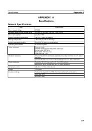
8.1. Ratings and Specifications ............................................................................. 8-2<br />
8.2. Single-phase 200V <strong>XtraDrive</strong> and Motors Combinations ............................ 8-6<br />
8.3. Three-phase 200V <strong>XtraDrive</strong> and Motor Combinations............................... 8-7<br />
8.4. Three-phase 400V <strong>XtraDrive</strong> and Motors Combinations............................. 8-8<br />
8.5. Base-mounted Dimensional Drawings ........................................................ 8-10<br />
8.5.1. <strong>XD</strong>-P3 to -02 (1-phase 200V, 30 to 200 W)..........................................8-10<br />
8.5.2. <strong>XD</strong>-04 (1-phase 200 V, 400 W).............................................................8-11<br />
8.5.3. <strong>XD</strong>-08 (1-phase 200V, 0.75kW) and <strong>XD</strong>-10 (3-phase 200V, 1.0kW).8-12<br />
8.5.4. <strong>XD</strong>-05, 10, 15 (3-phase 400V, 0.5 to 1.5kW) .......................................8-13<br />
8.5.5. <strong>XD</strong>-20, -30 (3-phase 200V,400V, 2.0 and 3.0 kW) ..............................8-14<br />
8.6. Rack-mounted Dimensional Drawings........................................................ 8-15<br />
8.6.1. <strong>XD</strong>-P3 to -02 (1-phase 200V, 30 to 200 W)..........................................8-15<br />
8.6.2. <strong>XD</strong>-04 (1-phase 200 V, 400 W).............................................................8-16<br />
8.6.3. <strong>XD</strong>-08 (1-phase 200V, 0.75kW) and <strong>XD</strong>-10 (3-phase 200V, 1.0kW).8-17<br />
8.6.4. <strong>XD</strong>-05, 10, 15 (3-phase 400V, 0.5 to 1.5kW) .......................................8-18<br />
8.6.5. <strong>XD</strong>-20, -30 (3-phase 200V,400V, 2.0 and 3.0 kW) ..............................8-19<br />
9. Inspection, Maintenance, and Troubleshooting.............................................9-1<br />
9.1. <strong>XtraDrive</strong> Inspection and Maintenance......................................................... 9-2<br />
9.1.1. Servomotor Inspection.............................................................................. 9-2<br />
9.1.2. Servo Amplifier Inspection ...................................................................... 9-2<br />
9.1.3. Replacing the Battery for the Absolute Encoder ..................................... 9-3<br />
9.2. Troubleshooting.............................................................................................. 9-4<br />
9.2.1. Troubleshooting Problems with Alarm Displays .................................... 9-4<br />
9.2.2. Troubleshooting Problems with No Alarm Display..............................9-25<br />
9.2.3. Alarm Display Table...............................................................................9-26<br />
9.2.4. Warning Displays ...................................................................................9-28<br />
Appendix A. Host Controller Connection Examples ......................................A-1<br />
A.1. Connecting the GL-series MC20 Motion Module ........................................A-2<br />
A.2. Connecting the CP-9200SH Servo Controller Module (SVA).....................A-3<br />
A.3. Connecting the GL-series B2813 Positioning Module .................................A-4<br />
A.4. Connecting OMRON's C500-NC222 Position Control Unit........................A-5<br />
A.5. Connecting OMRON's C500-NC112 Position Control Unit........................A-6<br />
A.6. Connecting MITSUBISHI's AD72 Positioning Unit....................................A-7<br />
A.7. Connecting MITSUBISHI's AD75 Positioning Unit....................................A-8<br />
Appendix B. Special Wiring ..............................................................................B-1<br />
B.1. Wiring Precautions.........................................................................................B-2<br />
B.2. Wiring for Noise Control ...............................................................................B-5<br />
B.3. Using More Than One <strong>XtraDrive</strong> ..................................................................B-9<br />
x
<strong>XtraDrive</strong> <strong>User</strong> <strong>Manual</strong> Table of Contents/Preface<br />
B.4. Extending Encoder Cables ...........................................................................B-10<br />
B.5. 400V Power Supply Voltage .......................................................................B-12<br />
B.6. Reactor for Harmonic Suppression..............................................................B-14<br />
Appendix C. Specifications for Peripheral Devices.........................................C-1<br />
C.1. Connector Terminal Block Converter Unit JUSP-TA50P............................C-2<br />
C.2. External Regenerative Resistors ....................................................................C-4<br />
C.3. DC Reactors for Power Supplies Designed for Minimum Harmonics........C-6<br />
C.4. Brake Power Supplies ....................................................................................C-8<br />
C.5. Surge Suppressor............................................................................................C-9<br />
C.6. Magnetic Contactor ........................................................................................C-9<br />
C.7. Variable Resistor for Speed Setting...............................................................C-9<br />
C.8. CN1 I/O Signal Connector.............................................................................C-9<br />
C.9. Connecting Pulse A/B Encoder without C Pulse (Index Pulse) .................C-10<br />
C.10. Absolute Encoder Battery ............................................................................C-11<br />
C.11. Cable for Connecting PC to <strong>XtraDrive</strong>........................................................C-12<br />
C.12. Connecting Regenerative Resistors .............................................................C-14<br />
C.13. Connecting Yaskawa Option Board ............................................................C-18<br />
C.13.1. Attaching the Option Board................................................................... C-18<br />
C.13.2. Detaching the Option Board.................................................................. C-18<br />
Appendix D. List of Parameters........................................................................D-1<br />
D.1. Parameters ......................................................................................................D-2<br />
D.2. Switches..........................................................................................................D-7<br />
D.3. Input Signal Selections................................................................................ D-11<br />
D.3.1. Home Switches ...................................................................................... D-12<br />
D.3.2. Extended input signal selection............................................................. D-12<br />
D.4. Output Signal Selections ............................................................................. D-13<br />
D.4.1. Extended Output Signal Selection......................................................... D-13<br />
D.5. Auxiliary Functions..................................................................................... D-14<br />
D.6. Monitor Modes ............................................................................................ D-14<br />
xi
<strong>XtraDrive</strong> <strong>User</strong> <strong>Manual</strong> Table of Contents/Preface<br />
This page intentionally left blank.<br />
xii
<strong>XtraDrive</strong> <strong>User</strong> <strong>Manual</strong> Table of Contents/Preface<br />
Using This <strong>Manual</strong><br />
Intended Audience<br />
This manual is intended for the following users.<br />
• Those designing <strong>XtraDrive</strong> <strong>XD</strong>- Series servodrive systems.<br />
• Those installing or wiring <strong>XtraDrive</strong> <strong>XD</strong>- Series servodrives.<br />
• Those performing trial operation or adjustments of <strong>XtraDrive</strong> <strong>XD</strong>-<br />
Series servodrives.<br />
• Those maintaining or inspecting <strong>XtraDrive</strong> <strong>XD</strong>- Series<br />
servodrives.<br />
Description of Technical Terms<br />
In this manual, the following terms are defined as follows:<br />
• Servomotor = SGMAH/SGMPH/SGMGH/SGMSH or other<br />
compatible servomotor.<br />
• Servo Amplifier = <strong>XtraDrive</strong> Series <strong>XD</strong>- servo amplifier.<br />
• Servodrive = A set including a servomotor and servo amplifier.<br />
• Servo System = A servo control system that includes the<br />
combination of a servodrive with a host computer and peripheral<br />
devices.<br />
Indication of Inverted Signals<br />
In this manual, the names of inverted signals (ones that are valid when<br />
low) are written with a forward slash (/) before the signal name, as<br />
shown in the following equations:<br />
• S–ON = /S–ON<br />
• P–CON = /P–CON<br />
xiii
<strong>XtraDrive</strong> <strong>User</strong> <strong>Manual</strong> Table of Contents/Preface<br />
Safety Precautions<br />
The following precautions are for checking products upon delivery, installation,<br />
wiring, operation, maintenance and inspections.<br />
Checking Products upon Delivery<br />
CAUTION<br />
• Always use the servomotor and servo amplifier in one of the specified combinations.<br />
Not doing so may cause fire or malfunction.<br />
Installation<br />
CAUTION<br />
• Never use the products in an environment subject to water, corrosive gases, inflammable<br />
gases, or combustibles.<br />
Doing so may result in electric shock or fire.<br />
Wiring<br />
WARNING<br />
• Connect the ground terminal to a class 3 ground (100. or less).<br />
Improper grounding may result in electric shock or fire.<br />
CAUTION<br />
• Do not connect a three-phase power supply to the U, V, or W output terminals.<br />
Doing so may result in injury or fire.<br />
• Securely fasten the power supply terminal screws and motor output terminal screws.<br />
Not doing so may result in fire.<br />
Operation<br />
CAUTION<br />
• Never touch any rotating motor parts while the motor is running.<br />
Doing so may result in injury.<br />
xiv
<strong>XtraDrive</strong> <strong>User</strong> <strong>Manual</strong> Table of Contents/Preface<br />
CAUTION<br />
• Conduct trial operation on the servomotor alone with the motor shaft disconnected from<br />
machine to avoid any unexpected accidents.<br />
Not doing so may result in injury.<br />
• Before starting operation with a machine connected, change the settings to match the<br />
parameters of the machine.<br />
Starting operation without matching the proper settings may cause the machine to run out of<br />
control or malfunction.<br />
• Before starting operation with a machine connected, make sure that an emergency stop<br />
can be applied at any time.<br />
Not doing so may result in injury.<br />
• Do not touch the heat sinks during operation.<br />
Not doing so may result in burns due to high temperatures.<br />
Maintenance and Inspection<br />
WARNING<br />
• Do not remove the panel cover while the power is ON.<br />
Doing so carries a risk of electric shock.<br />
• Do not touch terminals for five minutes after the power has been turned OFF.<br />
Residual voltage may cause electric shock.<br />
• Never touch the inside of the servo amplifier.<br />
Doing so may result in electric shock.<br />
CAUTION<br />
• Do not disassemble the servomotor.<br />
Doing so may result in electric shock or injury<br />
• Do not attempt to change wiring while the power is ON.<br />
Doing so may result in electric shock or injury<br />
xv
<strong>XtraDrive</strong> <strong>User</strong> <strong>Manual</strong> Table of Contents/Preface<br />
General Precautions<br />
NOTE THE FOLLOWING TO ENSURE<br />
SAFE APPLICATION:<br />
• The drawings presented in this manual are sometimes shown without covers or protective<br />
guards. Always replace the cover or protective guard as specified first, and then operate the<br />
products in accordance with the manual.<br />
• The drawings presented in this manual are typical examples and may not match the product you<br />
received.<br />
• This manual is subject to change due to product improvement, specification modification, and<br />
manual improvement. When this manual is revised, the manual code is updated, and the new<br />
manual is published as a next edition. The edition number appears on the front and back covers.<br />
• If the manual must be ordered due to loss or damage, inform your nearest YET representative or<br />
one of the offices listed on the back of this manual.<br />
• YET will not take responsibility for the results of unauthorized modifications of this product.<br />
YET shall not be liable for any damages or troubles resulting from unauthorized modification.<br />
xvi
<strong>XtraDrive</strong> <strong>User</strong> <strong>Manual</strong> Chapter 1: Checking Product and Part Names<br />
1. Checking Product and Part Names<br />
This chapter describes the procedure for checking products upon delivery as<br />
well as names for product parts.<br />
1. Checking Product and Part Names ................................................................ 1-1<br />
1.1. Checking the <strong>XtraDrive</strong> Series Products on Delivery................................ 1-2<br />
1.1.1. Servo Amplifiers ................................................................................ 1-2<br />
1.2. Product Part Names.................................................................................... 1-3<br />
1.2.1. Servo Amplifiers ................................................................................ 1-3<br />
1.2.2. Model Numbers.................................................................................. 1-4<br />
1-1
<strong>XtraDrive</strong> <strong>User</strong> <strong>Manual</strong> Chapter 1: Checking Product and Part Names<br />
1.1. Checking the <strong>XtraDrive</strong> Series Products on Delivery<br />
The following procedure is suggested to check <strong>XtraDrive</strong> series products<br />
upon delivery.<br />
Use the following checklist when <strong>XtraDrive</strong> series products are delivered.<br />
Initial Inspection Comments<br />
Are the delivered products<br />
the ones that were ordered?<br />
Does the servomotor shaft<br />
rotate smoothly?<br />
Check the model numbers marked on<br />
the nameplates of the servomotor and<br />
servo amplifier. (Refer to the<br />
descriptions of model numbers on<br />
following pages)<br />
The servomotor shaft is normal if it<br />
can be turned smoothly by hand.<br />
Servomotors with brakes, however,<br />
cannot be turned manually.<br />
Is there any damage? Check the overall appearance, and<br />
check for damage or scratches that<br />
may have occurred during shipping.<br />
Are there any loose screws? Check screws for looseness using a<br />
screwdriver.<br />
If any of the above are faulty or incorrect, contact YET or an authorized<br />
distributor.<br />
1.1.1. Servo Amplifiers<br />
External Appearance and Nameplate Examples<br />
SERIAL NUMBER<br />
<strong>SERVO</strong>MOTOR OUTPUT<br />
APPLICABLE POWER SUPPLY<br />
1-2<br />
<strong>XtraDrive</strong> TYPE<br />
MS
<strong>XtraDrive</strong> <strong>User</strong> <strong>Manual</strong> Chapter 1: Checking Product and Part Names<br />
1.2. Product Part Names<br />
This section describes product part names.<br />
1.2.1. Servo Amplifiers<br />
The figure below shows the part names for servo amplifiers.<br />
1-3
<strong>XtraDrive</strong> <strong>User</strong> <strong>Manual</strong> Chapter 1: Checking Product and Part Names<br />
1.2.2. Model Numbers<br />
<strong>XtraDrive</strong> Series<br />
Max. Applicable<br />
Servomotor Power<br />
(see table below)<br />
Input Voltage:<br />
M - 200V<strong>AC</strong>, or<br />
T - 400V<strong>AC</strong><br />
Extended Functionality<br />
By Option Boards:<br />
S - no CN10 connector, or<br />
N - with CN10 connector<br />
Design Version #<br />
Blank, or 01-FF<br />
(optional)<br />
Blank, or<br />
R - Rack mounted, or<br />
V - Board coating<br />
(optional)<br />
<strong>XD</strong> - 01 - M S<br />
Blank, or Y followed by 1 to 4 alphanumeric characters<br />
to identify customer applications<br />
(optional)<br />
Output Capacity<br />
Code<br />
Max. Applicable<br />
Servomotor Power<br />
(kW)<br />
1-4<br />
Output Capacity<br />
Code<br />
01 R Y999<br />
Max. Applicable<br />
Servomotor Power<br />
(kW)<br />
P3 0.03 08 0.75<br />
P5 0.05 10 1.0<br />
01 0.10 15 1.5<br />
02 0.20 20 2.0<br />
04 0.40 30 3.0
<strong>XtraDrive</strong> <strong>User</strong> <strong>Manual</strong> Chapter 2: Installation<br />
2. Installation<br />
This chapter describes precautions for <strong>XtraDrive</strong> Series servomotor and servo<br />
amplifier installation.<br />
2.1. Servo Amplifiers ........................................................................................ 2-2<br />
2.1.1. Storage Conditions............................................................................. 2-2<br />
2.1.2. Installation Site .................................................................................. 2-2<br />
2.1.3. Orientation ......................................................................................... 2-3<br />
2.1.4. Installation.......................................................................................... 2-3<br />
2-1
<strong>XtraDrive</strong> <strong>User</strong> <strong>Manual</strong> Chapter 2: Installation<br />
2.1. Servo Amplifiers<br />
The <strong>XtraDrive</strong> servo amplifiers are base-mounted. Incorrect installation will<br />
cause problems. Follow the installation instructions below.<br />
2.1.1. Storage Conditions<br />
Store the servo amplifier within the following temperature range, as<br />
long as it is stored with the power cable disconnected.<br />
-20 to 85°C<br />
2.1.2. Installation Site<br />
The following precautions apply to the installation site.<br />
Situation Installation Precaution<br />
Installation in a Control Panel<br />
Installation Near a Heating Unit<br />
Installation Near a Source of Vibration<br />
Installation at a Site Exposed to<br />
Corrosive Gas<br />
Other Situations<br />
Design the control panel size, unit layout, and cooling<br />
method so the temperature around the servo amplifier does<br />
not exceed 55°C.<br />
Minimize heat radiated from the heating unit as well as any<br />
temperature rise caused by natural convection so the<br />
temperature around the servo amplifier does not exceed<br />
55°C.<br />
Install a vibration isolator beneath the servo amplifier to<br />
avoid subjecting it to vibration.<br />
Corrosive gas does not have an immediate effect on the<br />
servo amplifier, but will eventually cause electronic<br />
components and contactor-related devices to malfunction.<br />
Take appropriate action to avoid corrosive gas.<br />
Do not install the servo amplifier in hot and humid locations<br />
or locations subject to excessive dust or iron powder in the<br />
air.<br />
2-2
<strong>XtraDrive</strong> <strong>User</strong> <strong>Manual</strong> Chapter 2: Installation<br />
2.1.3. Orientation<br />
Install the servo amplifier perpendicular to the wall as shown in the<br />
figure. The servo amplifier must be oriented this way because it is<br />
designed to be cooled by natural convection or by a cooling fan.<br />
Secure the servo amplifier using the mounting holes. The number of<br />
holes varies (from two to four) with the frame size of the servo<br />
amplifier.<br />
2.1.4. Installation<br />
Follow the procedure below to install multiple servo amplifiers side by<br />
side in a control panel.<br />
2-3
<strong>XtraDrive</strong> <strong>User</strong> <strong>Manual</strong> Chapter 2: Installation<br />
Servo Amplifier Orientation<br />
Install the servo amplifier perpendicular to the wall so the front panels’<br />
connectors faces outward.<br />
Cooling<br />
As shown in the figure above, allow sufficient space around each servo<br />
amplifier for cooling by cooling fans or natural convection.<br />
Side-by-side Installation<br />
When installing servo amplifiers side by side as shown in the figure<br />
above, allow at least 0.39in (10mm) between and at least 1.97in<br />
(50mm) above and below each servo amplifier. Install cooling fans<br />
above the servo amplifiers to avoid excessive temperature rise and to<br />
maintain even temperature inside the control panel.<br />
Environmental Conditions in the Control Panel<br />
• Ambient Temperature: 0 to 55°C<br />
• Humidity: 90% RH or less<br />
• Vibration: 0.5 G (4.9m/s 2 )<br />
• Condensation and Freezing: None<br />
• Ambient Temperature for Long-term Reliability: 45°C max.<br />
2-4
<strong>XtraDrive</strong> <strong>User</strong> <strong>Manual</strong> Chapter 3: Wiring<br />
3. Wiring<br />
This chapter describes the procedure used to connect <strong>XtraDrive</strong> Series products<br />
to peripheral devices and gives typical examples of main circuit wiring as well<br />
as I/O signal connections.<br />
3.1. Connecting to Peripheral Devices...............................................................3-2<br />
3.1.1. Single-Phase 200V Main Circuit Specifications.................................3-3<br />
3.1.2. Single-Phase 0.8kW 200V Main Circuit Specifications.....................3-4<br />
3.1.3. Three-phase 200V Main Circuit Specifications..................................3-5<br />
3.1.4. Three-Phase 400V Main Circuit Specifications .................................3-6<br />
3.2. <strong>XtraDrive</strong> Internal Block Diagrams............................................................3-7<br />
3.2.1. Single-phase 30W to 800W, 200V Models ........................................3-7<br />
3.2.2. Three-phase 1kW to 3kW, 200V Models ...........................................3-8<br />
3.2.3. Three-phase 0.5kW to 3.0kW, 400V Models .....................................3-9<br />
3.3. Main Circuit Wiring..................................................................................3-10<br />
3.3.1. Names and Descriptions of Main Circuit Terminal..........................3-11<br />
3.3.2. Typical Main Circuit Wiring Example .............................................3-12<br />
3.3.3. Servo Amplifier Power Losses .........................................................3-13<br />
3.3.4. Wiring Main Circuit Terminal Blocks..............................................3-14<br />
3.4. I/O Signals ................................................................................................3-15<br />
3.4.1. Example of Typical I/O Signal Connections ....................................3-15<br />
3.4.2. List of CN1 Terminals ......................................................................3-16<br />
3.4.3. I/O Signal Names and Functions ......................................................3-17<br />
3.4.4. Interface Circuits...............................................................................3-19<br />
3.5. Wiring Encoders (for SGMGH and SGMSH Motors Only) ....................3-23<br />
3.5.1. Encoder Connections ........................................................................3-23<br />
3.5.2. CN2 Encoder Connector Terminal Layout and Types .....................3-25<br />
3.5.3. Encoder Cables Interconnections......................................................3-26<br />
3.6. Examples of Standard Connections ..........................................................3-28<br />
3-1
<strong>XtraDrive</strong> <strong>User</strong> <strong>Manual</strong> Chapter 3: Wiring<br />
3.1. Connecting to Peripheral Devices<br />
This section provides examples of standard <strong>XtraDrive</strong> Series product<br />
connections to peripheral devices.<br />
It also briefly explains how to connect each peripheral device.<br />
3-2
<strong>XtraDrive</strong> <strong>User</strong> <strong>Manual</strong> Chapter 3: Wiring<br />
3.1.1. Single-Phase 200V Main Circuit Specifications<br />
3-3
<strong>XtraDrive</strong> <strong>User</strong> <strong>Manual</strong> Chapter 3: Wiring<br />
3.1.2. Single-Phase 0.8kW 200V Main Circuit Specifications<br />
<strong>XtraDrive</strong> <strong>XD</strong>-08-MS has been changed from three-phase specifications to singlephase.<br />
Main circuit connection terminals (L1, L2, L3) remained.<br />
These devices have terminal B3 and internal regenerative resistor. Observe the<br />
following points.<br />
1. Connect main power supply shown below to L1 and L3 terminals. Power supply is<br />
single-phase, 220 to 230 V<strong>AC</strong> +10% to –15%, 50/60Hz. If power supply of 187V<br />
(-15% of 220V) or less is used, alarm A.41 indicating voltage shortage, may occur<br />
when accelerating to max speed with max torque of motor.<br />
2. Short-circuit B2 and B3 terminals using the internal regenerative resistor. If<br />
capacity of the regenerative resistor is insufficient, remove the lead between B2<br />
and B3 terminals and connect an external regenerative resistor unit to B1 and B2<br />
terminals.<br />
3-4
<strong>XtraDrive</strong> <strong>User</strong> <strong>Manual</strong> Chapter 3: Wiring<br />
3.1.3. Three-phase 200V Main Circuit Specifications<br />
3-5
<strong>XtraDrive</strong> <strong>User</strong> <strong>Manual</strong> Chapter 3: Wiring<br />
3.1.4. Three-Phase 400V Main Circuit Specifications<br />
3-6
<strong>XtraDrive</strong> <strong>User</strong> <strong>Manual</strong> Chapter 3: Wiring<br />
3.2. <strong>XtraDrive</strong> Internal Block Diagrams<br />
The following sections show internal block diagrams of the servo amplifiers.<br />
3.2.1. Single-phase 30W to 800W, 200V Models<br />
3-7
<strong>XtraDrive</strong> <strong>User</strong> <strong>Manual</strong> Chapter 3: Wiring<br />
3.2.2. Three-phase 1kW to 3kW, 200V Models<br />
3-8
<strong>XtraDrive</strong> <strong>User</strong> <strong>Manual</strong> Chapter 3: Wiring<br />
3.2.3. Three-phase 0.5kW to 3.0kW, 400V Models<br />
3-9
<strong>XtraDrive</strong> <strong>User</strong> <strong>Manual</strong> Chapter 3: Wiring<br />
3.3. Main Circuit Wiring<br />
This section shows typical examples of main circuit wiring for <strong>XtraDrive</strong><br />
Series servo products, functions of main circuit terminals, and the power ON<br />
sequence.<br />
Observe the following precautions when wiring.<br />
CAUTION<br />
• Do not bundle or run power and signal lines together in the same duct. Keep power and<br />
signal lines separated by at least 30cm (11.81 in).<br />
Not doing so may cause a malfunction.<br />
• Use twisted pair wires or multi-core shielded-pair wires for signal and encoder (PG)<br />
feedback lines.<br />
The maximum length is 3m (118.11 in) for reference input lines and is 20m (787.40 in) for PG<br />
feedback lines.<br />
• Do not touch the power terminals for 5 minutes after turning power OFF because high<br />
voltage may still remain in the servo amplifier.<br />
Make sure the charge indicator is out first before starting an inspection.<br />
• Avoid frequently turning power ON and OFF. Do not turn power ON or OFF more than<br />
once per minute.<br />
Since the servo amplifier has a capacitor in the power supply, a high charging current flows<br />
for 0.2s when power is turned ON. Frequently turning power ON and OFF causes main power<br />
devices like capacitors and fuses to deteriorate, resulting in unexpected problems.<br />
3-10
<strong>XtraDrive</strong> <strong>User</strong> <strong>Manual</strong> Chapter 3: Wiring<br />
Terminal<br />
Symbol<br />
3.3.1. Names and Descriptions of Main Circuit Terminal<br />
The following table gives the names and a description of main circuit<br />
terminals.<br />
Table 3.1: Main Circuit Names and Description<br />
Name Description<br />
L1, L2 30W to 1kW Single-phase 200 to 230V (+10%, -15%), 50/60Hz<br />
L1, L2, L3*<br />
U, V, W<br />
L1C, L2C<br />
24V, 0V<br />
(2 places)<br />
B1, B2 or<br />
B1, B2, B3<br />
1, 2<br />
Main circuit <strong>AC</strong> input<br />
terminal<br />
Servomotor connection<br />
terminal<br />
Control power input<br />
terminal<br />
1kW to 3kW Three-phase 200 to 230V (+10%, -15%), 50/60Hz<br />
2kW to 3.0kW 400V Three-phase 380 to 480V (+10%, -15%), 50/60Hz<br />
Connects to the Servomotor.<br />
30W to 3.0kW<br />
3-11<br />
Single-phase 200 to 230V (+10%, -15%), 50/60Hz<br />
Three-phase 200 to 230V (+10%, -15%), 50/60Hz<br />
24VDC (±15%) 400V units only<br />
Ground terminal Connects to the power supply ground terminals and motor ground terminal.<br />
External regenerative<br />
resistor terminal<br />
DC reactor terminal<br />
connection for power<br />
supply harmonic wave<br />
countermeasure<br />
Main circuit Positive<br />
terminal<br />
Main circuit Negative<br />
terminal<br />
30W to 400W<br />
800W to 3.0kW<br />
Normally not connected.<br />
Connect an external regenerative resistor<br />
(provided by customer) between B1 and B2 if the<br />
regenerative capacity is insufficient.<br />
Note: No B3 terminal.<br />
Normally short B2 and B3 (for an internal<br />
regenerative resistor).<br />
Remove the wire between B2 and B3 and connect<br />
an external regenerative resistor (provided by<br />
customer) between B1 and B2 if the capacity of<br />
the internal regenerative resistor is insufficient.<br />
Normally short 1 and 2.<br />
If a countermeasure against power supply harmonic waves is needed,<br />
connect a DC reactor between 1 and 2.<br />
The amplifier is delivered from the factory with these terminals shorted.<br />
See 5.8.6 Reactor for Harmonic Suppression for details.<br />
Normally not connected.<br />
Normally not connected.<br />
*<strong>XtraDrive</strong> <strong>XD</strong>-08 has single-phase, 200V power supply specifications. Connect the<br />
following power supply between L1 and L3.<br />
Single-phase 220 to 230 V<strong>AC</strong> +10%, -15% (50/60Hz)<br />
When a power supply of 187V(-15% of 220V) or less is used, an alarm 41, indicating<br />
voltage shortage, may occur when accelerating to max speed with max torque of motor.
<strong>XtraDrive</strong> <strong>User</strong> <strong>Manual</strong> Chapter 3: Wiring<br />
3.3.2. Typical Main Circuit Wiring Example<br />
The following figure shows a typical example of main circuit wiring.<br />
Designing a Power ON Sequence<br />
Note the following when designing the power ON sequence.<br />
• Design the power ON sequence so that power is turned OFF when a<br />
servo alarm signal is output. (See the circuit figure above.)<br />
• Hold the power ON button for at least two seconds. The servo<br />
amplifier will output a servo alarm signal for two seconds or less<br />
when power is turned ON. This is required in order to initialize the<br />
servo amplifier.<br />
Power supply<br />
Servo alarm (ALM)<br />
output signal<br />
3-12<br />
2.0 s max.
<strong>XtraDrive</strong> <strong>User</strong> <strong>Manual</strong> Chapter 3: Wiring<br />
3.3.3. Servo Amplifier Power Losses<br />
The following table shows servo amplifier power losses at the rated<br />
output.<br />
Main<br />
Circuit<br />
Power<br />
Supply<br />
Singlephase<br />
200V<br />
Threephase<br />
200V<br />
Threephase<br />
400V<br />
Table 3.2: Servo Amplifier Power Losses at Rated Output<br />
Maximum<br />
Applicable<br />
Servomotor<br />
Capacity<br />
[kW]<br />
Servo Amplifier<br />
Model<br />
Output<br />
Current<br />
(Effective<br />
Value) [A]<br />
3-13<br />
Main<br />
Circuit<br />
Power<br />
Loss<br />
[W]<br />
Regenerative<br />
Resistor<br />
Power Loss<br />
[W]<br />
Control<br />
Circuit<br />
Power<br />
Loss<br />
[W]<br />
Total<br />
Power<br />
Loss<br />
[W]<br />
0.10 <strong>XD</strong>-01-** 0.91 6.7 19.7<br />
0.20 <strong>XD</strong>-02-** 2.1 13.3 — 13 26.3<br />
0.40 <strong>XD</strong>-04-** 2.8 20<br />
33<br />
0.75 <strong>XD</strong>-08-** 4.4 47 12 15 74<br />
1.0 <strong>XD</strong>-10-** 7.6 55 12 82<br />
2.0<br />
3.0<br />
<strong>XD</strong>-20-**<br />
<strong>XD</strong>-30-**<br />
18.5<br />
7.5<br />
120<br />
60<br />
28<br />
15 163<br />
198<br />
0.45 <strong>XD</strong>-05-** 1.9 19 48<br />
1.0 <strong>XD</strong>-10-** 3.5 35 14<br />
64<br />
1.5 <strong>XD</strong>-15-** 5.4 53<br />
15 82<br />
2.0<br />
3.0<br />
<strong>XD</strong>-20-**<br />
<strong>XD</strong>-30-**<br />
8.4<br />
11.9<br />
83<br />
118<br />
28<br />
161<br />
243<br />
Note: Regenerative resistor power losses are allowable losses. Take the following action if this value is<br />
exceeded:<br />
• Disconnect the internal regenerative resistor in the servo amplifier by removing the wire<br />
between terminals B2 and B3.<br />
• Install an external regenerative resistor between terminals B1 and B2.<br />
See 5.6 Selecting a Regenerative Resistor for more details on the resistors.
<strong>XtraDrive</strong> <strong>User</strong> <strong>Manual</strong> Chapter 3: Wiring<br />
3.3.4. Wiring Main Circuit Terminal Blocks<br />
Observe the following precautions when wiring main circuit terminal<br />
blocks.<br />
CAUTION<br />
• Remove the terminal block from the servo amplifier prior to wiring.<br />
• Insert only one wire per terminal on the terminal block.<br />
• Make sure that the core wire is not electrically shorted to adjacent core wires.<br />
• Reconnect any wires that were accidentally pulled out.<br />
Servo amplifiers with a capacity below 1.5kW will have connector-type<br />
terminal blocks for main circuit terminals. Follow the procedure below when<br />
connecting to the terminal block.<br />
Connection Procedure<br />
• Strip the end of the wire, leaving the ends twisted together.<br />
• Open the wire insert opening of the terminal block (plug) with a tool<br />
using either of the two procedures shown in Fig. A and Fig. B on the<br />
following page.<br />
1. Fig. A: Use the provided lever to open the wire insert opening .<br />
Fig. B: Using a commercially available 1/8in (3.0 to 3.5mm)<br />
slotted screwdriver, press down firmly on the screwdriver insert<br />
opening to release the wire insert slot.<br />
2. Figs A and B: Insert the wire end into the opening and then<br />
clamp it tightly by releasing either the lever or the screwdriver.<br />
3-14
<strong>XtraDrive</strong> <strong>User</strong> <strong>Manual</strong> Chapter 3: Wiring<br />
3.4. I/O Signals<br />
This section describes I/O signals for the <strong>XtraDrive</strong> servo amplifier.<br />
3.4.1. Example of Typical I/O Signal Connections<br />
3-15
<strong>XtraDrive</strong> <strong>User</strong> <strong>Manual</strong> Chapter 3: Wiring<br />
3.4.2. List of CN1 Terminals<br />
The following diagram shows the layout and specifications of CN1<br />
terminals.<br />
2 SG GND<br />
4 SEN<br />
6 SG GND<br />
SEN signal<br />
input<br />
8 /PULS Reference<br />
pulse input<br />
10 SG GND<br />
12 /SIGN Reference<br />
symbol input<br />
14 /CLR Clear input<br />
16 TMON<br />
18 PL3<br />
20 /PCO<br />
Analog<br />
Monitor Output<br />
Open-collector<br />
reference<br />
power supply<br />
PG divided<br />
output<br />
C-phase<br />
22 BAT (-) Battery (-)<br />
24 — —<br />
Table 3.3: CN1 Terminal Layout<br />
1 SG GND<br />
3 PL1<br />
Open-collector<br />
reference<br />
power supply<br />
5 V-REF Reference<br />
speed input<br />
7 PULS Reference<br />
pulse input<br />
9 T-REF Torque<br />
reference input<br />
11 SIGN<br />
13 PL2<br />
Reference sign<br />
input<br />
Open-collector<br />
reference<br />
power supply<br />
15 CLR Clear input<br />
17 VTG<br />
19 PCO<br />
Analog Monitor<br />
Output<br />
PG divided<br />
output Cphase<br />
21 BAT (+) Battery (+)<br />
23 — —<br />
25 /V-CMP+<br />
Speed<br />
coincidence<br />
(/COIN+)<br />
detection output<br />
3-16<br />
27 /TGON+<br />
29 /SRDY+<br />
31 ALM+<br />
33 PAO<br />
35 PBO<br />
37 AL01<br />
39 AL03<br />
41 P-CON<br />
43 N-OT<br />
45 /P-CL<br />
47 +24V -IN<br />
TGON signal<br />
output<br />
Servo ready<br />
output<br />
Servo alarm<br />
output<br />
PG divided<br />
output Aphase<br />
PG divided<br />
output Bphase<br />
Alarm code<br />
output<br />
Opencollector<br />
output<br />
P operation<br />
input<br />
Reverse<br />
overtravel<br />
input<br />
Forward<br />
current limit<br />
ON input<br />
External<br />
input power<br />
supply<br />
49 /PSO S-phase<br />
signal output<br />
Note: 1. Do not use unused terminals for relays.<br />
2. Connect the shield of the I/O signal cable to the connector’s shell.<br />
3. Connect to the FG (frame ground) at the servo amplifier-end connector.<br />
CN1 Specifications<br />
<strong>XtraDrive</strong> Internal<br />
Connector<br />
10250-52A2JL or Equivalent<br />
50-pin Right Angle Plug<br />
26 /V-CMP-<br />
Speed coincidence<br />
detection<br />
(/COIN-)<br />
output<br />
28 /TGON<br />
30 /S-RDY<br />
32 ALM<br />
34 /PAO<br />
36 /PBO<br />
38 AL02<br />
40 /S-ON<br />
42 P-OT<br />
44<br />
/ALMRS<br />
T<br />
46 /N-CL<br />
TGON signal<br />
output<br />
Servo ready<br />
output<br />
Servo alarm<br />
output<br />
PG divided<br />
output Aphase<br />
PG divided<br />
output Bphase<br />
Alarm code<br />
output<br />
Servo ON<br />
input<br />
Forward<br />
overtravel<br />
input<br />
Alarm reset<br />
input<br />
Reverse<br />
current limit<br />
ON input<br />
48 PSO S-phase<br />
signal output<br />
50 — —<br />
Applicable Receptacle Kit (YET P/N: 4J4003)<br />
Connector Case Manufacturer<br />
MDR 10150-3000VE 50-pin 10350-52A0-008<br />
Sumitomo 3M<br />
Co.
<strong>XtraDrive</strong> <strong>User</strong> <strong>Manual</strong> Chapter 3: Wiring<br />
3.4.3. I/O Signal Names and Functions<br />
The following section describes servo amplifier I/O signal names and<br />
functions.<br />
Input Signals<br />
Signal Name<br />
Common<br />
Speed<br />
Referenc<br />
e<br />
Torque<br />
Referenc<br />
e<br />
Position<br />
Referenc<br />
e<br />
Pin<br />
No.<br />
/S-ON 40<br />
/P-CON 41<br />
P-OT<br />
N-OT<br />
/P-CL<br />
/N-CL<br />
/ALM<br />
-RST<br />
42<br />
43<br />
45<br />
46<br />
3-17<br />
Function<br />
Servo ON: Turns ON the servomotor when the gate block<br />
in the inverter is released.<br />
* Function selected via parameter.<br />
Reference<br />
5.5.2<br />
5.2.1<br />
5.2.7<br />
Proportional Switches the speed control loop from PI<br />
operation (proportional/integral) to P (proportional) 5.2.1<br />
reference control when ON.<br />
Direction<br />
reference<br />
Control mode<br />
switching<br />
With internal reference speed selected:<br />
Switches the direction of rotation.<br />
Position Speed Enables<br />
Speed Torque control mode<br />
Torque Speed<br />
switching.<br />
5.2.6<br />
5.2.7<br />
Zero-clamp<br />
reference<br />
Speed control with zero-clamp function:<br />
reference speed is zero when ON.<br />
5.4.3<br />
Reference<br />
pulse block<br />
Position control with reference pulse stop:<br />
stops reference pulse input when ON.<br />
5.2.10<br />
Forward Run<br />
prohibited<br />
Reverse Run<br />
prohibited<br />
Overtravel prohibited: stops servomotor<br />
when movable part travels beyond the<br />
allowable range of motion.<br />
5.1.2<br />
* Function selected with a parameter.<br />
Forward<br />
—<br />
current limit ON<br />
Reverse<br />
current limit ON<br />
Current limit function used when ON. 5.1.3<br />
Internal<br />
speed<br />
switching<br />
With internal reference speed selected:<br />
switches the internal speed settings.<br />
5.2.6<br />
44 Alarm reset: Releases the servo alarm state. 5.5.1<br />
+24VIN 47<br />
Control power supply input for sequence signals: users<br />
must provide the +24V power supply.<br />
5.2.4<br />
SEN 4 (2) Initial data request signal when using an absolute encoder. 5.2.3<br />
BAT+<br />
BAT-<br />
21<br />
22<br />
Connecting pins for the absolute encoder backup battery. 5.2.3<br />
V-REF 5 (6)<br />
T-REF<br />
PULS<br />
/PULS<br />
SIGN<br />
/SIGN<br />
CLR<br />
/CLR<br />
PL1<br />
PL2<br />
PL3<br />
9<br />
(10)<br />
7<br />
8<br />
11<br />
12<br />
15<br />
14<br />
3<br />
13<br />
18<br />
Speed reference input: ±2 to ±10V/rated motor speed<br />
(Input gain can be modified with a parameter.)<br />
Torque reference input: ±1 to ±10V/rated motor speed<br />
(Input gain can be modified with a parameter.)<br />
Corresponds<br />
to reference<br />
pulse input<br />
Line-driver<br />
Opencollector<br />
Input mode<br />
• Code + pulse string<br />
• CCW/CW pulse<br />
• Two-phase pulse (90° phase differential)<br />
Error counter clear: Clears the error counter during<br />
position control.<br />
+12V pull-up power supply when PULS, SIGN and CLR<br />
reference signals is open-collector outputs (+12V power<br />
supply is built into the servo amplifier).<br />
Note: 1. The functions allocated to /S-ON, /P-CON. P-OT, N-OT, /ALM-RST, /P-CL, and /N-CL input<br />
signals can be changed with parameters. (See 5.3.3 Input Circuit Signal Allocation.)<br />
2. Pin numbers in parenthesis ( ) indicate signal grounds.<br />
3. The voltage input range for speed and torque references is a maximum of ±12V.<br />
5.2.1<br />
5.2.1<br />
5.2.1<br />
5.2.1<br />
5.2.1
<strong>XtraDrive</strong> <strong>User</strong> <strong>Manual</strong> Chapter 3: Wiring<br />
Output Signals<br />
Signal Name<br />
Common<br />
Speed<br />
Position<br />
Not used.<br />
ALM+<br />
ALM-<br />
/TGON+<br />
/TGON-<br />
/S-RDY+<br />
/S-RDY-<br />
PAO<br />
/PAO<br />
PBO<br />
/PBO<br />
PCO<br />
/PCO<br />
PSO<br />
/PSO<br />
ALO1<br />
ALO2<br />
ALO3<br />
Pin<br />
No.<br />
31<br />
32<br />
27<br />
28<br />
9<br />
30<br />
33(1)<br />
34<br />
35<br />
36<br />
19<br />
20<br />
48<br />
49<br />
37<br />
38<br />
39(1)<br />
3-18<br />
Function Reference<br />
Servo alarm: Turns OFF when an error is detected. 5.5.1<br />
Detection during servomotor rotation: detects<br />
whether the servomotor is rotating at a speed higher<br />
than the motor speed setting. Motor speed detection<br />
can be set via parameter.<br />
Servo ready: ON if there is no servo alarm when the<br />
control/main circuit power supply is turned ON.<br />
A phase<br />
signal<br />
B phase<br />
signal<br />
C phase<br />
signal<br />
S phase<br />
signal<br />
Converted two-phase pulse (A and<br />
B phase) encoder output signal<br />
and origin pulse (C phase) signal:<br />
RS-422 or the equivalent.<br />
With an absolute encoder: outputs<br />
serial data corresponding to the<br />
number of revolutions (RS-422 or<br />
equivalent).<br />
Alarm code output: Outputs 3-bit alarm codes.<br />
Open-collector: 30V and 20mA rating maximum.<br />
TMON 16 Analog monitor signal<br />
VTG 17 Analog monitor signal<br />
/V-CMP+<br />
/V-CMP-<br />
/COIN+<br />
/COIN-<br />
25<br />
26<br />
25<br />
26<br />
23<br />
24<br />
50<br />
Speed coincidence (output in Speed Control Mode):<br />
detects whether the motor speed is within the<br />
setting range and if it matches the reference speed<br />
value.<br />
Positioning completed (output in Position Control<br />
Mode): turns ON when the number of error pulses<br />
reaches the value set. The setting is the number of<br />
error pulses set in reference units (input pulse units<br />
defined by the electronic gear).<br />
These terminals are not used.<br />
Do not connect relays to these terminals.<br />
5.5.5<br />
5.5.6<br />
5.2.3<br />
5.5.1<br />
5.5.4<br />
5.5.3<br />
Note: 1. Pin numbers in parenthesis () indicate signal grounds.<br />
2. The functions allocated to /TGON, /S-RDY, and /V-CMP (/COIN) can be changed via parameters.<br />
Functions /CLT, /VCT, /BK, /WARN, and /NEAR signals can also be changed. (See 5.3.4 Output<br />
Circuit Signal Allocation).<br />
—
<strong>XtraDrive</strong> <strong>User</strong> <strong>Manual</strong> Chapter 3: Wiring<br />
3.4.4. Interface Circuits<br />
This section shows examples of servo amplifier I/O signal connection to<br />
the host controller.<br />
Interface for Reference Input Circuits<br />
Analog Input Circuit<br />
Analog signals are either speed or torque reference signals at the<br />
impedance below.<br />
• Speed reference input: About 14kΩ<br />
• Torque reference input: About 14kΩ<br />
The maximum allowable voltage for input signals is ±12V.<br />
Reference Position Input Circuit<br />
An output circuit for the reference pulse and error counter clear signal<br />
at the host controller can be either line-driver or open-collector outputs.<br />
These are shown below by type.<br />
• Line-driver Output Example:<br />
• Open-collector Output, Example 1: External power supply<br />
3-19
<strong>XtraDrive</strong> <strong>User</strong> <strong>Manual</strong> Chapter 3: Wiring<br />
The following examples show how to select the pull-up resistor R1 so<br />
the input current (I) falls between 7 and 15mA.<br />
R1 =2.2kΩ with<br />
VCC = 24V ±5%<br />
Application Examples<br />
R1 =1kΩ with<br />
VCC = 12V ±5%<br />
3-20<br />
R1 =180Ω with<br />
VCC = 5V ±5%<br />
• Open-collector Output, Example 2: Using a servo amplifier with an<br />
internal 12V power supply<br />
This circuit uses the 12V power supply built into the servo<br />
amplifier. The input is not isolated in this case.<br />
Sequence Input Circuit Interface<br />
The sequence input circuit interface connects through a relay or opencollector<br />
transistor circuit. Select a low-current relay; otherwise a faulty<br />
contact will result.
<strong>XtraDrive</strong> <strong>User</strong> <strong>Manual</strong> Chapter 3: Wiring<br />
Output Circuit Interfaces<br />
Any of the following three types of servo amplifier output circuits can<br />
be used. Connect an input circuit at the host controller following one of<br />
these types.<br />
• Connecting to a Line-driver Output Circuit<br />
Encoder serial data converted to two-phase (A and B phase) pulse<br />
output signals (PAO, /PAO, PBO, /PBO), origin pulse signals (PCO,<br />
/PCO) and S phase rotation signals (PCO, /PCO) are output via linedriver<br />
output circuits that normally comprise the position control<br />
system at the host controller. Connect the line-driver output circuit<br />
through a line receiver circuit at the host controller.<br />
See 3.5 Wiring Encoders for connection circuit examples.<br />
• Connecting to an Open-collector Output Circuit<br />
Alarm code signals are output from open-collector transistor output<br />
circuits.<br />
Connect an open-collector output circuit through an optocoupler,<br />
relay, or line receiver circuit.<br />
Note: The maximum allowable voltage and current capacities for open-collector circuits are:<br />
• Voltage: 30V DC<br />
• Current: 20mA DC<br />
3-21
<strong>XtraDrive</strong> <strong>User</strong> <strong>Manual</strong> Chapter 3: Wiring<br />
• Connecting an optocoupler output circuit<br />
An optocoupler output circuits are used for servo alarm, servo ready,<br />
and other sequence output signal circuits.<br />
Connect an optocoupler output circuit through a relay or line<br />
receiver circuit.<br />
Note: The maximum allowable capacities for optocoupler output circuits are:<br />
• Voltage: 30VDC<br />
• Current: 50mADC<br />
• Connecting two <strong>XtraDrive</strong>s (master-slave mode)<br />
Connect output of “master” <strong>XtraDrive</strong> to “slave” <strong>XtraDrive</strong>’s input.<br />
• Connecting an external load to <strong>XtraDrive</strong>’s output.<br />
Maximum current: 50mA.<br />
3-22
<strong>XtraDrive</strong> <strong>User</strong> <strong>Manual</strong> Chapter 3: Wiring<br />
3.5. Wiring Encoders (for SGMGH and SGMSH Motors Only)<br />
The following sections describe the procedure for wiring a servo amplifier to<br />
the encoder.<br />
3.5.1. Encoder Connections<br />
The following diagrams show the wiring of the encoder output from the<br />
motor to CN2 of the servo amplifier, and PG output signals from CN1<br />
to the controller. This applies to both incremental and absolute encoders<br />
of SGMGH and SGMSH motors only.<br />
Incremental Serial Encoders<br />
3-23
<strong>XtraDrive</strong> <strong>User</strong> <strong>Manual</strong> Chapter 3: Wiring<br />
Absolute Serial Encoders<br />
Incremental A/B+C Encoders<br />
3-24
<strong>XtraDrive</strong> <strong>User</strong> <strong>Manual</strong> Chapter 3: Wiring<br />
3.5.2. CN2 Encoder Connector Terminal Layout and Types<br />
The following tables describe CN2 connector terminal layout and types.<br />
CN2 Connector Terminal Layout<br />
1 PPG0V PG GND<br />
3 PPG0V PG GND<br />
5 PPG5V PG +5V<br />
7 NC* -<br />
9 /PS<br />
Serial PG<br />
/S-phase<br />
2 PPG0V PG GND<br />
4 PPG5V PG +5V<br />
6 PPG5V PG +5V<br />
8 PS<br />
10 SPG5V<br />
Note: NC* – Leave contact open.<br />
Serial PG<br />
S-phase<br />
Serial PG<br />
+5V<br />
3-25<br />
11 SPG0V<br />
13 BAT-<br />
15 /PC<br />
17 /PA<br />
19 /PB<br />
Serial PG<br />
GND<br />
Battery “ –“<br />
input<br />
PG<br />
/C-phase<br />
PG<br />
/A-phase<br />
PG<br />
/B-phase<br />
12 BAT+<br />
14 PC<br />
16 PA<br />
18 PB<br />
Battery ”+”<br />
input<br />
PG<br />
C-phase<br />
PG<br />
A-phase<br />
PG<br />
B-phase<br />
20 NC* -<br />
Optional: CN2 Connector with Commutation Sensors<br />
Terminal Layout<br />
1 PPG0V PG GND<br />
3 PPG0V PG GND<br />
5 PPG5V PG +5V<br />
7 /UIN<br />
9 /VIN<br />
U – Phase<br />
Hall Effect<br />
V – Phase<br />
Hall Effect<br />
Note: NC* – Leave contact open.<br />
2 PPG0V PG GND<br />
4 PPG5V PG +5V<br />
6 PPG5V PG +5V<br />
8 NC* -<br />
10 SPG5V +5V<br />
CN2 Connector Models<br />
11 SPG0V GND<br />
13 BAT-<br />
15 /PC<br />
17 /PA<br />
19 /PB<br />
Battery ” –“<br />
input<br />
PG<br />
/C-phase<br />
PG<br />
/A-phase<br />
PG<br />
/B-phase<br />
<strong>XtraDrive</strong><br />
Internal<br />
Applicable Plug (or Socket)<br />
Connector Soldered Plug Case<br />
10220-52A2JL<br />
20 PIN<br />
MDR 10120-3000VE 20PIN<br />
(YET P/N: 4J4001)<br />
10320-52A0-008<br />
(YET P/N: 4J0101)<br />
12 BAT+<br />
14 PC<br />
16 PA<br />
18 PB<br />
20 /WIN<br />
Battery “+”<br />
input<br />
PG<br />
C-phase<br />
PG<br />
A-phase<br />
PG<br />
B-phase<br />
W – Phase<br />
Hall Effect<br />
Soldered Plug<br />
(Servomotor<br />
Side)<br />
54280-0600 6PIN<br />
(YET P/N: 4J1521)<br />
Note: The motor-end relay socket connects to the encoder connector for the SGMAH and SGMPH<br />
servomotors.
<strong>XtraDrive</strong> <strong>User</strong> <strong>Manual</strong> Chapter 3: Wiring<br />
3.5.3. Encoder Cables Interconnections<br />
This chapter shows interconnections for all standard encoder cables<br />
available from YET (Refer to YET Part Number). For additional types<br />
of encoders (like with communication sensors etc.) contact your YET<br />
representative.<br />
Absolute A/B Encoder Cable<br />
For Yaskawa SGM motors. (P/N 004143)<br />
<strong>XtraDrive</strong> side<br />
20-pin connector<br />
PPG0V 1,2,3<br />
PPG5V 4,5,6<br />
BAT+ 12<br />
BAT- 13<br />
PC 14<br />
/PC 15<br />
PA 16<br />
/PA 17<br />
PB 18<br />
/PB 19<br />
FG Case<br />
BL<strong>AC</strong>K<br />
RED<br />
ORANGE<br />
WHITE<br />
GREEN<br />
WHITE/GREEN<br />
BLUE<br />
WHITE/BLUE<br />
YELLOW<br />
WHITE<br />
YELLOW/GREEN<br />
Cable Shield<br />
P - Twisted pair.<br />
Incremental A/B Encoder Cable<br />
For Yaskawa SGM motors. (P/N 004144)<br />
<strong>XtraDrive</strong> side<br />
20-pin connector<br />
PPG0V 1,2,3<br />
PPG5V 4,5,6<br />
PC 14<br />
/PC 15<br />
PA 16<br />
/PA 17<br />
PB 18<br />
/PB 19<br />
FG Case<br />
BL<strong>AC</strong>K<br />
RED<br />
GREEN<br />
WHITE/GREEN<br />
BLUE<br />
WHITE/BLUE<br />
YELLOW<br />
WHITE<br />
YELLOW/GREEN<br />
Cable Shield<br />
P - Twisted pair.<br />
3-26<br />
Motor side<br />
15-pin connector<br />
P<br />
P<br />
P<br />
P<br />
P<br />
P<br />
P<br />
7 0V<br />
8 +5V<br />
15 +3.6V<br />
14 0V<br />
5 C<br />
6 /C<br />
1 A<br />
2 /A<br />
3 B<br />
4 /B<br />
9 FG<br />
Motor side<br />
9-pin connector<br />
7 0V<br />
8 +5V<br />
5 C<br />
6 /C<br />
1 A<br />
2 /A<br />
3 B<br />
4 /B<br />
9 FG
<strong>XtraDrive</strong> <strong>User</strong> <strong>Manual</strong> Chapter 3: Wiring<br />
Absolute Serial Encoder Cable<br />
Battery<br />
connector<br />
BAT+ 1<br />
BAT- 2<br />
For Yaskawa SGMAH motors. (P/N 004139)<br />
<strong>XtraDrive</strong> side<br />
20-pin connector<br />
SPG5V 10<br />
SPG0V 11<br />
12<br />
13<br />
PS 8<br />
/PS 9<br />
FG Shield<br />
P - Twisted pair.<br />
3-27<br />
RED<br />
BL<strong>AC</strong>K<br />
ORANGE<br />
WHITE/ORANGE<br />
BLUE<br />
WHITE/BLUE<br />
Cable Shield<br />
Incremental Serial Encoder Cable<br />
For Yaskawa SGMAH motors. (P/N 004140)<br />
<strong>XtraDrive</strong> side<br />
20-pin connector<br />
SPG5V 10<br />
SPG0V 11<br />
BAT+ 12<br />
BAT- 13<br />
PS 8<br />
/PS 9<br />
FG Shield<br />
RED<br />
BL<strong>AC</strong>K<br />
ORANGE<br />
P - Twisted pair.<br />
WHITE/ORANGE<br />
BLUE<br />
WHITE/BLUE<br />
Cable Shield<br />
P<br />
P<br />
Motor side<br />
6-pin connector<br />
P<br />
P<br />
Motor side<br />
6-pin connector<br />
1 PG5V<br />
2 GND<br />
3 PGBAT+<br />
4 PGBAT-<br />
5 PS<br />
6 /PS<br />
Shield FG<br />
1 PG5V<br />
2 GND<br />
3 PGBAT+<br />
4 PGBAT-<br />
5 PS<br />
6 /PS<br />
Shield FG
<strong>XtraDrive</strong> <strong>User</strong> <strong>Manual</strong> Chapter 3: Wiring<br />
3.6. Examples of Standard Connections<br />
The following diagrams show examples of standard servo amplifier<br />
connections by specifications and type of control.<br />
Note for single-phase power supply specifications:<br />
<strong>XtraDrive</strong> <strong>XD</strong>-08** have changed from three-phase specifications to singlephase.<br />
Main circuit connection terminals (L1, L2, L3) remained.<br />
These devices have terminal B3 and internal regenerative resistor. Observe<br />
the following points.<br />
1. Connect main power supply shown below to L1 and L3 terminals. Power<br />
supply is single-phase, 220 to 230 V<strong>AC</strong> +10% to –15%, 50/60Hz. If<br />
power supply of 187V (-15% of220V) or less is used, alarm A41<br />
indicating voltage shortage, may occur when accelerating to max speed<br />
with max torque of motor.<br />
2. Short-circuit B2 and B3 terminals using the internal regenerative resistor.<br />
If capacity of the regenerative resistor is insufficient, remove the lead<br />
between B2 and B3 terminals and connect an external regenerative<br />
resistor unit to B1 and B2 terminals.<br />
3-28
<strong>XtraDrive</strong> <strong>User</strong> <strong>Manual</strong> Chapter 3: Wiring<br />
Position Control Mode<br />
*1. P represents twisted-pair wires<br />
*2. The time constant for the primary filter is 47us.<br />
*3. Connect only with an absolute encoder.<br />
3-29<br />
*7. These circuits are SELV circuits, therefore are<br />
separated from all other circuits by double and<br />
reinforced insulator.<br />
*4. Used only with an absolute encoder. *8. Use a double-insulated 24-VDC power supply.<br />
*5. Connect an external regenerative resistor<br />
*9. Optional – not available in all models.<br />
between terminals B1 and B2.(for <strong>XtraDrive</strong>s with big<br />
capacity)<br />
*10. Resistors are different for each model.<br />
*6. These circuits are hazardous, therefore are<br />
separated by protecting separator.<br />
*11. ∅ Represents contacts of CN1 connector
<strong>XtraDrive</strong> <strong>User</strong> <strong>Manual</strong> Chapter 3: Wiring<br />
Speed Control Mode<br />
*1. P represents twisted-pair wires<br />
*2. The time constant for the primary filter is 47us.<br />
*3. Connect only with an absolute encoder.<br />
3-30<br />
*7. These circuits are SELV circuits, therefore are<br />
separated from all other circuits by double and<br />
reinforced insulator.<br />
*4. Used only with an absolute encoder. *8. Use a double-insulated 24-VDC power supply.<br />
*5. Connect an external regenerative resistor<br />
*9. Optional – not available in all models.<br />
between terminals B1 and B2.(for <strong>XtraDrive</strong>s with big<br />
capacity)<br />
*10. Resistors are different for each model.<br />
*6. These circuits are hazardous, therefore are<br />
separated by protecting separator.<br />
*11. ∅ Represents contacts of CN1 connector
<strong>XtraDrive</strong> <strong>User</strong> <strong>Manual</strong> Chapter 3: Wiring<br />
Torque Control Mode<br />
*1. P represents twisted-pair wires<br />
*2. The time constant for the primary filter is 47us.<br />
*3. Connect only with an absolute encoder.<br />
3-31<br />
*7. These circuits are SELV circuits, therefore are<br />
separated from all other circuits by double and<br />
reinforced insulator.<br />
*4. Used only with an absolute encoder. *8. Use a double-insulated 24-VDC power supply.<br />
*5. Connect an external regenerative resistor<br />
*9. Optional – not available in all models.<br />
between terminals B1 and B2.(for <strong>XtraDrive</strong>s with big<br />
capacity)<br />
*10. Resistors are different for each model.<br />
*6. These circuits are hazardous, therefore are<br />
separated by protecting separator.<br />
*11. ∅ Represents contacts of CN1 connector
<strong>XtraDrive</strong> <strong>User</strong> <strong>Manual</strong> Chapter 3: Wiring<br />
This page intentionally left blank.<br />
3-32
<strong>XtraDrive</strong> <strong>User</strong> <strong>Manual</strong> Chapter 4: Trial Operation<br />
4. Trial Operation<br />
This chapter describes a two-step trial operation. Be sure to complete step 1<br />
before proceeding to step 2.<br />
4.1. Two-Step Trial Operation .......................................................................... 4-2<br />
4.1.1. Step 1: Trial Operation for Servomotor without Load....................... 4-3<br />
4.1.2. Step 2: Trial Operation with Servomotor Connected to Machine..... 4-9<br />
4.2. Additional Setup Procedures in Trial Operation...................................... 4-10<br />
4.2.1. Servomotors with Brakes ................................................................. 4-10<br />
4.2.2. Position Control by Host Controller ................................................ 4-11<br />
4.3. Minimum Parameters and Input Signals.................................................. 4-12<br />
4.3.1. Parameters........................................................................................ 4-12<br />
4.3.2. Input Signals .................................................................................... 4-12<br />
4-1
<strong>XtraDrive</strong> <strong>User</strong> <strong>Manual</strong> Chapter 4: Trial Operation<br />
4.1. Two-Step Trial Operation<br />
Make sure that all wiring is completed prior to starting trial operation.<br />
For your own safety, perform the trial operation in the order given below<br />
(step 1 and 2). See 4.1.1 Trial Operation for Servomotor without Load and<br />
4.1.2 Trial Operation for Servomotor Connected to Mashine for more details<br />
on the trial operation.<br />
Step 1: Trial Operation for Servomotor without Load<br />
Make sure the Servomotor is wired properly and then turn the<br />
shaft prior to connecting the Servomotor to the equipment.<br />
Step 2: Trial Operation with the Equipment and Servomotor Connected<br />
<strong>XtraDrive</strong><br />
Adjust the Servomotor according to equipment characteristics,<br />
connect the Servomotor to the equipment, and perform the trial<br />
operation.<br />
Servomotor<br />
Adjust speed by autotuning.<br />
Connect to the equipment<br />
4-2
<strong>XtraDrive</strong> <strong>User</strong> <strong>Manual</strong> Chapter 4: Trial Operation<br />
4.1.1. Step 1: Trial Operation for Servomotor without Load<br />
Caution<br />
• Do not operate the servomotor while it is connected to the equipment.<br />
To prevent accidents, initially perform step 1 where the trial operation is conducted under noload<br />
conditions (with all couplings and belts disconnected).<br />
In step 1, make sure that the servomotor is wired properly as shown<br />
below. Incorrect wiring is generally the reason why servomotors fail to<br />
operate properly during trial operation.<br />
• Check main power supply circuit wiring.<br />
• Check servomotor wiring.<br />
• Check CN1 I/O signal wiring.<br />
Make sure the host controller and other adjustments are completed as<br />
much as possible in step 1 (prior to connecting the servomotor to<br />
equipment).<br />
Note: Check the items on the following pages in the order given during the servomotor trial operation.<br />
See 4.2.1 Servomotors with Brakes, if you are using a servomotor with brakes.<br />
4-3
<strong>XtraDrive</strong> <strong>User</strong> <strong>Manual</strong> Chapter 4: Trial Operation<br />
1. Secure the servomotor.<br />
Secure the servomotor mounting plate to the equipment in order to<br />
prevent the servomotor from moving during operation.<br />
2. Check the wiring.<br />
Disconnect the CN1 connector and check the servomotor wiring in<br />
the power supply circuit. CN1 I/O signals are not used, so leave the<br />
connector disconnected.<br />
3. Turn ON power.<br />
Normal display<br />
Example of alarm display<br />
4-4<br />
Alternative display<br />
Turn ON the servo amplifier’s power. If the servo amplifier has<br />
turned ON normally, the LED display on its front panel will appear<br />
as shown above. Power is not supplied to the servomotor because<br />
the servo is OFF.<br />
If an alarm display appears on the LED indicator as shown above,<br />
the power supply circuit, servomotor wiring, or encoder wiring is<br />
incorrect. In this case, turn OFF power and take appropriate action.<br />
See 9.2 Troubleshooting.<br />
Note: If an absolute encoder is used, it must be set up. Refer to 5.7.4 Absolute Encoder Setup.
<strong>XtraDrive</strong> <strong>User</strong> <strong>Manual</strong> Chapter 4: Trial Operation<br />
4. Operate with the panel operator.<br />
Operate the servomotor using the panel operator. Check to see if the<br />
servomotor runs normally.<br />
See 7.2.2 JOG Operation for more details on the procedure.<br />
5. Connect the signal lines.<br />
Use the following procedure to connect the CN1 connector.<br />
a) Turn OFF power.<br />
b) Connect the CN1 connector.<br />
c) Turn ON power again.<br />
6. Check the input signals.<br />
Check input signal wiring in Monitor Mode using the panel<br />
operator. See 7.1.6 Operation in Monitor Mode for more details on<br />
the procedure.<br />
Turn ON and OFF each signal line to see if the LED monitor bit<br />
display on the panel changes as shown below.<br />
Input signal LED display<br />
P-OT<br />
N-OT<br />
/ALM-RST<br />
/P-CL<br />
/N-CL<br />
SEN<br />
4-5<br />
/P-CON<br />
/S-ON<br />
Top lights when OFF (high level).<br />
Bottom lights when ON (low level).
<strong>XtraDrive</strong> <strong>User</strong> <strong>Manual</strong> Chapter 4: Trial Operation<br />
Input Signal Status LED Display<br />
OFF (high level) Top LED indicators light.<br />
ON (low level) Bottom LED indicators light.<br />
Note: The servomotor will not operate properly if the following signal lines are not wired correctly. Always<br />
wire them correctly. Short-circuit the signal lines if they will be unused. Input signal selections<br />
(parameters Pn50A to Pn50D) can be used to eliminate the need for external short-circuiting.<br />
Signal Symbol Connector Pin<br />
Number<br />
P-OT CN1-42<br />
N-OT CN1-43<br />
/S-ON CN1-40<br />
+24VIN CN1-47<br />
4-6<br />
Description<br />
The servomotor can rotate in forward direction<br />
when this signal line is low (0V).<br />
The servomotor can rotate in reverse direction<br />
when this signal line is low (0V).<br />
The servomotor is turned ON when this signal<br />
line is low (0V). Leave the servomotor OFF.<br />
Control power supply terminal for sequence<br />
signals.<br />
Note: IF an absolute encoder is being used, the servo will not turn ON when the servo ON signal (/S-ON) is<br />
input unless the SEN signal is also ON.<br />
When the SEN signal is checked in Monitor mode, the top of the LED will light because the SEN signal<br />
is high when ON.<br />
7. Turn ON the servo.<br />
0V<br />
/S-ON<br />
<strong>XtraDrive</strong><br />
CN1-40<br />
Turn ON servo.<br />
Servomotor<br />
Turn ON the servo using the following procedure.<br />
a) Make sure there are no reference signal inputs.<br />
• Set V-REF (CN1-5) and T-REF (CN1-9) to 0V for speed<br />
and torque control.<br />
• Set PULS (CN1-7) and SIGN (CN1-11) to low for position<br />
control.<br />
b) Turn ON the servo ON signal.<br />
Display with servo ON.
<strong>XtraDrive</strong> <strong>User</strong> <strong>Manual</strong> Chapter 4: Trial Operation<br />
Set /S-ON (CN1-40) to 0V. If everything is normal, the<br />
servomotor will turn ON and the LED indicator on the front<br />
panel will display as shown above. If an alarm display appears,<br />
take appropriate action as described in 9.2 Troubleshooting.<br />
Note: If there is noise in the reference voltage for speed control, the “-” on the left of the 7-segment LED may<br />
flash.<br />
Operation Using Reference Input<br />
The operating procedure here depends on the parameter settings<br />
(control mode selection at memory switch Pn000.1). Use the following<br />
procedure for operations with speed and position control.<br />
Operating Procedure in Speed Control Mode:<br />
Set Pn000.1 to 0<br />
This description applies to the standard speed control setting.<br />
V-REF<br />
SG<br />
<strong>XtraDrive</strong><br />
CN1-5<br />
CN1-6<br />
4-7<br />
Servomotor<br />
Servomotor rotates at a speed proportional<br />
to the reference voltage.<br />
1. Gradually increase the reference speed input (V-REF, CN1-5)<br />
voltage. The servomotor will rotate.<br />
2. Check the following items in Monitor mode. See 7.1.6 Operation in<br />
Monitor Mode.<br />
Un000 Actual motor speed<br />
Un001 Reference speed<br />
• Has the reference speed been input?<br />
• Is the motor speed as defined?<br />
• Does the reference speed coincide with the actual motor speed?<br />
• Does the servomotor stop when the speed reference is 0?<br />
3. If the servomotor rotates at extremely slow speed with 0V specified<br />
for the reference voltage, correct the reference offset value as<br />
described in 7.2.3 Automatic Adjustment of the Speed and Torque<br />
Reference Offset or 7.2.4 <strong>Manual</strong> Adjustment of the Speed and<br />
Torque Reference Offset.<br />
4. Reset the following parameters to change the motor speed or<br />
direction of rotation.<br />
Pn300<br />
Pn000.0<br />
Sets the reference speed input gain.<br />
See 5.2.1 Speed Reference.<br />
Selects the rotation direction.<br />
See 5.1.1 Switching Servomotor Rotation<br />
Direction.
<strong>XtraDrive</strong> <strong>User</strong> <strong>Manual</strong> Chapter 4: Trial Operation<br />
Reference<br />
pulse<br />
Operating Procedure In Position Control Mode:<br />
Set Pn000.1 to 1<br />
1. Set the parameter Pn200.0 so that the reference pulse form is the<br />
same as the host controller output form.<br />
To select the reference pulse form: See 5.2.2 Position Reference.<br />
2. Input a slow speed pulse from the host controller and execute lowspeed<br />
operation.<br />
Host controller<br />
PULS<br />
/PULS<br />
SIGN<br />
/SIGN<br />
4-8<br />
<strong>XtraDrive</strong><br />
CN1-7<br />
CN1-8<br />
CN1-11<br />
CN1-12<br />
Servomotor<br />
3. Check the following data in Monitor mode. See 7.1.6 Operation in<br />
Monitor Mode.<br />
Un000 Actual motor speed<br />
Un007 Reference pulse speed display<br />
Un008 Position offset<br />
• Has the reference pulse been input?<br />
• Is the motor speed as defined?<br />
• Does the reference speed coincide with the actual motor speed?<br />
• Does the servomotor stop when the speed reference is 0?<br />
4. Reset the parameters shown below to change the motor speed or<br />
direction of rotation.<br />
Pn202, Pn203<br />
Pn000.0<br />
Electronic gear ratio<br />
See 5.2.5 Using the Electronic Gear Function.<br />
Selects the direction of rotation.<br />
See 5.1.1 Switching Servomotor Rotation Direction.<br />
If an alarm occurs or the servomotor fails to operate during the<br />
above operation, the CN1 connector wiring is incorrect or the<br />
parameter settings do not match the host controller specifications.<br />
Check the wiring and review the parameter settings, then repeat<br />
step 1.<br />
Note: References<br />
• List of alarms: See 9.2.3 Alarm Display Table.<br />
• List of parameters: See Appendix D List of Parameters.
<strong>XtraDrive</strong> <strong>User</strong> <strong>Manual</strong> Chapter 4: Trial Operation<br />
4.1.2. Step 2: Trial Operation with Servomotor Connected to<br />
Machine<br />
Warning<br />
Follow the procedure below for step 2 operation precisely as given.<br />
Malfunctions that occur after the servomotor is connected to the equipment not only damage the<br />
equipment, but may also cause an accident resulting in death or injury.<br />
Before proceeding to step 2, repeat step 1 (servomotor trial operation<br />
without a load) until all concerns including parameters and wiring have<br />
fully satisfied expectations.<br />
After step 1 has been completed, proceed to step 2 for trial operation<br />
with the servomotor connected to the equipment. The servo amplifier is<br />
now adjusted in the following ways to meet the specific equipment’s<br />
characteristics.<br />
• Using autotuning to match the servo amplifier to the equipment’s<br />
characteristics.<br />
• Matching direction of rotation and speed to the equipment’s<br />
specifications.<br />
• Checking the final control form.<br />
<strong>XtraDrive</strong><br />
Servomotor<br />
Connect to the machine<br />
Follow the procedure below to perform the trial operation.<br />
1. Make sure power is OFF.<br />
2. Connect the servomotor to the equipment.<br />
See 2.1 Servomotors for more details on connecting the servomotor.<br />
3. Use autotuning to match the servo amplifier to equipment<br />
characteristics.<br />
See 6.3 Autotuning.<br />
4. Operate the servomotor by reference input.<br />
As in step 1 (Servomotor Trial Operation without Load), operate the<br />
servomotor by reference input as described in 4.1.1 Step 1: Trial<br />
Operation for Servomotor without Load. Tune to match the host<br />
controller at this time, as well.<br />
5. Set and record user settings.<br />
Set parameters as required and record all settings for later use during<br />
maintenance.<br />
Note: The servomotor will not be broken in completely during the trial operation. Therefore, let the system<br />
run for a sufficient amount of time after trial operation has been completed to ensure that it is properly<br />
broken in.<br />
4-9
<strong>XtraDrive</strong> <strong>User</strong> <strong>Manual</strong> Chapter 4: Trial Operation<br />
4.2. Additional Setup Procedures in Trial Operation<br />
For two equipment configurations, which are delineated in the subsequent<br />
sections, precautionary setup procedures must be followed before starting trial<br />
operation.<br />
4.2.1. Servomotors with Brakes<br />
Use a servomotor with a brake for vertical shaft applications or for the<br />
application of external force to the shaft to prevent rotation due to<br />
gravity or external force during a power loss.<br />
The servo amplifier uses the brake interlock output (/BK) signal to<br />
control the holding brake operation when using servomotors with<br />
brakes.<br />
Vertical shaft<br />
Servomotor<br />
Holding brake<br />
Prevents the<br />
Servomotor from<br />
rotating due to gravity.<br />
4-10<br />
Shaft with External Force Applied<br />
External<br />
force<br />
Servomotor<br />
Note: To prevent faulty operation when using gravity or external force, first make sure that both the<br />
servomotor and the holding brake work properly. When assured that each operates properly, connect the<br />
servomotor to the rest of the equipment to start the trial operation.<br />
Single-phase<br />
200V<br />
The following figure shows wiring for a servomotor with brakes. See<br />
5.4.4 Using the Holding Brake for details on wiring.<br />
Power supply<br />
Single-phase 200V<br />
Magnetic contactor<br />
<strong>XtraDrive</strong><br />
U,V,W<br />
CN 2<br />
(90VDC)<br />
Brake power supply<br />
LPSE-2H01 (200-V input)<br />
Servomotor with brakes<br />
Encoder<br />
M PG
<strong>XtraDrive</strong> <strong>User</strong> <strong>Manual</strong> Chapter 4: Trial Operation<br />
4.2.2. Position Control by Host Controller<br />
Controller<br />
Reference<br />
JOG<br />
Operation<br />
(Constant<br />
Reference<br />
Speed Input<br />
from Host<br />
Controller)<br />
Simple<br />
Positioning<br />
Overtravel<br />
(P-OT and<br />
N-OT Used)<br />
If the position control algorithm of the host controller has not been<br />
established or finalized, disconnect the servomotor from the equipment<br />
before performing a trial operation. This will prevent the servomotor<br />
from running out of control and damaging the equipment.<br />
Host<br />
controller<br />
Reference<br />
speed<br />
<strong>XtraDrive</strong> M<br />
Speed control<br />
4-11<br />
Trial operation for<br />
servomotor without load<br />
Check servomotor operation as described in the following table.<br />
Check Procedure Description<br />
Motor speed<br />
Number of<br />
motor<br />
rotations<br />
Whether the<br />
servomotor<br />
stops rotating<br />
when P-OT<br />
and N-OT<br />
signals are<br />
applied<br />
Check motor speed as follows:<br />
• Use the speed monitor (Un000) on<br />
the Panel Operator.<br />
Run the servomotor at low speed.<br />
Input a reference speed of 60rpm, for<br />
example, to see if the servomotor<br />
makes one revolution per second.<br />
Input a reference equivalent to one<br />
servomotor rotation and visually<br />
check to see if the shaft makes one<br />
revolution.<br />
Check to see if the servomotor stops<br />
when P-OT and N-OT signals are<br />
input during continuous servomotor<br />
operation.<br />
Check the parameter<br />
setting at Pn300 to see<br />
if the reference speed<br />
gain is correct.<br />
Check the parameter<br />
setting at Pn201 to see<br />
if the number of<br />
dividing pulses is<br />
correct.<br />
Review P-OT and N-<br />
OT wiring if the<br />
servomotor does not<br />
stop.
<strong>XtraDrive</strong> <strong>User</strong> <strong>Manual</strong> Chapter 4: Trial Operation<br />
4.3. Minimum Parameters and Input Signals<br />
This section describes the minimum parameters and input signals required for<br />
trial operation.<br />
4.3.1. Parameters<br />
See 7.1.5 Operation in Parameter Setting Mode for more details on<br />
setting parameters.<br />
Turn power OFF once after changing any parameter except Pn300.<br />
The change will not be valid until power is restored.<br />
Basic Parameters<br />
Pn000.1<br />
Speed Control<br />
Function Selection Basic Switches:<br />
Control Mode Selection<br />
4-12<br />
See 5.3.5<br />
Pn300 Speed Reference See 5.2.1<br />
Pn201 Using the Encoder Signal Output See 5.2.3<br />
Position Control<br />
Pn200.0 Position Reference See 5.2.2<br />
Pn202 Using the Electronic Gear Function (Numerator) See 5.2.5<br />
Pn203 Using the Electronic Gear Function (Denominator) See 5.2.5<br />
Changing Servomotor Rotation Direction<br />
If the specified direction differs from the actual direction of rotation,<br />
wiring may be incorrect . Recheck the wiring and correct if necessary.<br />
Use the following parameter to reverse the direction of rotation.<br />
Pn000.0 Switching Servomotor Rotation Direction See 5.1.1<br />
4.3.2. Input Signals<br />
Input signal selection settings through parameters can be used to<br />
eliminate the need for external short circuits.<br />
Signal Name Pin Number Description<br />
/S-ON Servo ON CN1-40<br />
P-OT<br />
N-OT<br />
Forward run<br />
prohibited<br />
Reverse run<br />
prohibited<br />
CN1-42<br />
CN1-43<br />
See 5.5.2 for more details on turning<br />
ON and OFF the servomotor.<br />
See 5.1.2 for more details on the<br />
overtravel limit switch.
<strong>XtraDrive</strong> <strong>User</strong> <strong>Manual</strong> Chapter 5: Parameter Settings and Functions<br />
5. Parameter Settings and Functions<br />
5.1. Settings According to Device Characteristics.............................................5-4<br />
5.1.1. Switching Servomotor Rotation Direction..........................................5-4<br />
5.1.2. Setting the Overtravel Limit Function ................................................5-5<br />
5.1.3. Limiting Torque..................................................................................5-8<br />
5.2. Settings According to Host Controller......................................................5-12<br />
5.2.1. Speed Reference................................................................................5-12<br />
5.2.2. Position Reference ............................................................................5-14<br />
5.2.3. Using the Encoder Signal Output .....................................................5-20<br />
5.2.4. Sequence I/O Signals ........................................................................5-23<br />
5.2.5. Using the Electronic Gear Function..................................................5-25<br />
5.2.6. Contact Input Speed Control.............................................................5-29<br />
5.2.7. Using Torque Control .......................................................................5-34<br />
5.2.8. Torque Feed-Forward Function ........................................................5-40<br />
5.2.9. Torque Limiting by Analog Voltage Reference ...............................5-42<br />
5.2.10. Reference Pulse Inhibit Function (/INHIBIT) ..................................5-44<br />
5.3. Setting Up the Servo Amplifier ................................................................5-45<br />
5.3.1. Parameters.........................................................................................5-45<br />
5.3.2. JOG Speed ........................................................................................5-46<br />
5.3.3. Input Circuit Signal Allocation.........................................................5-46<br />
5.3.4. Output Circuit Signal Allocation ......................................................5-50<br />
5.3.5. Control Mode Selection ....................................................................5-52<br />
5.4. Setting Stop Functions ..............................................................................5-54<br />
5.4.1. Adjusting Offset................................................................................5-54<br />
5.4.2. Servo OFF Stop Mode Selection ......................................................5-55<br />
5.4.3. Using the Zero Clamp Function........................................................5-56<br />
5.4.4. Using the Holding Brake ..................................................................5-58<br />
5.5. Forming a Protective Sequence ................................................................5-61<br />
5.5.1. Using Servo Alarm and Alarm Code Outputs ..................................5-61<br />
5.5.2. Using the Servo ON Input Signal (/S-ON) .......................................5-63<br />
5.5.3. Using the Positioning Completed Output Signal (/COIN) ...............5-64<br />
5.5.4. Speed Coincidence Output (/V-CMP) ..............................................5-65<br />
5.5.5. Using the Running Output Signal (/TGON) .....................................5-67<br />
5.5.6. Using the Servo Ready Output Signal (/S-RDY) .............................5-68<br />
5.5.7. Using the Warning Output Signal (/WARN)....................................5-69<br />
5.5.8. Handling Power Loss........................................................................5-71<br />
5.6. Selecting a Regenerative Resistor.............................................................5-72<br />
5.6.1. External Regenerative Resistor.........................................................5-73<br />
5.6.2. Calculating the Regenerative Power Capacity..................................5-74<br />
5.7. Absolute Encoders ....................................................................................5-78<br />
5.7.1. Interface Circuit ................................................................................5-79<br />
5.7.2. Configuring an Absolute Encoder ....................................................5-80<br />
5.7.3. Absolute Encoder Setup....................................................................5-81<br />
5.7.4. Absolute Encoder Reception Sequence ............................................5-84<br />
5.8. AB Encoders .............................................................................................5-89<br />
5.9. Configuration of Serial Commands for AB Encoders ..............................5-91<br />
5.9.1. Position Control ................................................................................5-91<br />
5.9.1.1. Defining <strong>User</strong> Units for Motion Profiles ......................................5-91<br />
5.9.1.2. Position Units................................................................................5-91<br />
5-1
<strong>XtraDrive</strong> <strong>User</strong> <strong>Manual</strong> Chapter 5: Parameter Settings and Functions<br />
5.9.1.3. Speed Units ...................................................................................5-92<br />
5.9.1.4. Acceleration Units ........................................................................5-93<br />
5.9.1.5. Setting Default Motion Profile Parameters...................................5-94<br />
5.9.1.6. Profile Speed (Pn2A2, Pn2A3) .....................................................5-95<br />
5.9.1.7. Profile Acceleration (Pn2A4, Pn2A5) ..........................................5-95<br />
5.9.1.8. Jerk Smoothing Time (Pn2A6) .....................................................5-95<br />
5.9.1.9. Quick Stop Deceleration (Pn2A8, Pn2A9) ...................................5-96<br />
5.9.1.10. Motion End Window (Pn2C0)......................................................5-96<br />
5.9.2. Torque Control..................................................................................5-96<br />
5.9.3. Homing .............................................................................................5-97<br />
5.9.4. Digital I/O .........................................................................................5-98<br />
5.9.5. Auto Tuning......................................................................................5-99<br />
5.10. Auto Running a <strong>User</strong> Program..............................................................5-99<br />
5-2
<strong>XtraDrive</strong> <strong>User</strong> <strong>Manual</strong> Chapter 5: Parameter Settings and Functions<br />
Before Reading This Chapter<br />
This chapter describes the use of each CN1 connector I/O signals in the<br />
<strong>XtraDrive</strong> servo amplifier as well as the procedure for setting the<br />
related parameters for the intended purposes.<br />
The following sections can be used as references for this chapter.<br />
• List of CN1 I/O signals: See 3.4.3 I/O Signal Names and Functions.<br />
• CN1 I/O signal terminal layout: See 3.4.2 List of CN1 Terminals.<br />
• List of parameters: Appendix D List of Parameters.<br />
• Parameter setting procedure: 7.1.5 Operation in Parameter Setting<br />
Mode<br />
The CN1 connector is used to exchange signals with the host controller<br />
and external circuits.<br />
Parameter Configurations<br />
Type<br />
Function Selection Constants<br />
Servo Gain and Other<br />
Constants<br />
Position Control Constants<br />
Parameters are comprised of the types shown in the following table. See<br />
Appendix D List of Parameters.<br />
Parameter<br />
Number<br />
Pn000 to Pn007<br />
Pn550 to Pn551<br />
Pn100 to Pn11E<br />
Pn1A0 to Pn1C0<br />
Pn200 to Pn216<br />
Pn2A2 to Pn2CB<br />
Speed Control Constants Pn300 to Pn308<br />
Torque Control Constants Pn400 to Pn40A<br />
Sequence Constants<br />
Pn500 to Pn512<br />
Pn200 to Pn2D2<br />
Others Pn600 to Pn601<br />
Auxiliary Function Execution Fn000 to Fn014<br />
Monitor Modes Un000 to Un00D<br />
5-3<br />
Description<br />
Select basic and application functions such as<br />
the type of control or the stop mode used when<br />
an alarm occurs.<br />
Set numerical values (speed control).<br />
Set numerical values (position control).<br />
Set position control parameters such as the<br />
reference pulse input form gear ratio and<br />
application setting.<br />
Set speed control parameters such as speed<br />
reference input gain and soft start deceleration<br />
time.<br />
Set torque control parameters such as the<br />
torque reference input gain and<br />
forward/reverse torque limits.<br />
Set output conditions for all sequence signals<br />
and change I/O signal selections and<br />
allocations.<br />
Specify the capacity for an external<br />
regenerative resistor and reserved constants.<br />
Execute auxiliary functions such as JOG Mode<br />
operation.<br />
Enable speed and torque reference<br />
monitoring, as well as monitoring to check<br />
whether I/O signals are ON or OFF.<br />
Encoder Selection Pn190 to Pn193 Encoder type selection
<strong>XtraDrive</strong> <strong>User</strong> <strong>Manual</strong> Chapter 5: Parameter Settings and Functions<br />
5.1. Settings According to Device Characteristics<br />
This section describes the procedure for setting parameters according to the<br />
dimensions and performance characteristics of the equipment used.<br />
5.1.1. Switching Servomotor Rotation Direction<br />
<strong>XtraDrive</strong> has a Reverse Rotation mode that reverses the direction of<br />
servomotor rotation without rewiring. Forward rotation in the standard<br />
setting is defined as counterclockwise as viewed from the load.<br />
With the Reverse Rotation mode, the direction of servomotor rotation<br />
can be reversed without changing other parameters. Only the direction<br />
(+, −) of shaft motion is reversed.<br />
Forward Reference<br />
Reverse Reference<br />
Standard Setting Reverse Rotation Mode<br />
ccw<br />
Encoder output<br />
from<strong>XtraDrive</strong><br />
PAO (phase A)<br />
PBO (phase B)<br />
Encoder output<br />
from<strong>XtraDrive</strong><br />
PAO (phase A)<br />
PBO (phase B)<br />
Setting Reverse Rotation Mode<br />
cw<br />
Use the parameter Pn000.0.<br />
5-4<br />
cw<br />
ccw<br />
Encoder output<br />
from<strong>XtraDrive</strong><br />
PAO (phase A)<br />
PBO (phase B)<br />
Encoder output<br />
from<strong>XtraDrive</strong><br />
PAO (phase A)<br />
PBO (phase B)<br />
Parameter Signal Setting Control Mode<br />
Pn000.0 Direction Selection Default Setting: 0<br />
Speed/Torque Control,<br />
Position Control<br />
Use the following settings to select the direction of servomotor rotation.<br />
Setting Description<br />
0<br />
1<br />
Forward rotation is defined as counterclockwise<br />
(CCW) rotation as viewed from the load.<br />
Forward rotation is defined as clockwise (CW)<br />
rotation as viewed from the load.<br />
(Standard setting)<br />
(Reverse Rotation Mode)
<strong>XtraDrive</strong> <strong>User</strong> <strong>Manual</strong> Chapter 5: Parameter Settings and Functions<br />
5.1.2. Setting the Overtravel Limit Function<br />
The overtravel limit function forces movable equipment parts to stop if<br />
they exceed the allowable range of motion.<br />
Using the Overtravel Function<br />
To use the overtravel function, connect the overtravel limit switch input<br />
signal terminals shown below to the correct pins of the servo amplifier<br />
CN1 connector.<br />
Input P-OT CN1-42<br />
Input N-OT CN1-43<br />
Forward Run Prohibited<br />
(Forward Overtravel)<br />
Reverse Run Prohibited<br />
(Reverse Overtravel)<br />
5-5<br />
Speed/Torque Control,<br />
Position Control<br />
Speed/Torque Control,<br />
Position Control<br />
Connect limit switches as shown below to prevent damage of<br />
exuipment during linear motion.<br />
Reverse rotation end<br />
Servomotor<br />
Forward rotation end<br />
P- OT<br />
N - OT<br />
<strong>XtraDrive</strong><br />
CN1 -42<br />
CN1 -43<br />
The drive status with an input signal ON or OFF is shown in the<br />
following table.<br />
Signal State Input Level Description<br />
P-OT<br />
N-OT<br />
ON CN1-42: low<br />
OFF CN1-42: high<br />
ON CN1-43: low<br />
OFF CN1-43: high<br />
Enabling/Disabling Input Signals<br />
Forward rotation allowed, (normal<br />
operation status).<br />
Forward rotation prohibited<br />
(reverse rotation allowed).<br />
Reverse rotation allowed, (normal<br />
operation status).<br />
Reverse rotation prohibited<br />
(forward rotation allowed).<br />
Set the following parameters to specify whether input signals are used<br />
for overtravel or not. The default setting is “NOT USED.”<br />
Parameter Signal Setting Control Mode<br />
Pn50A.3<br />
Pn50B.0<br />
P-OT Signal Mapping<br />
(Forward Run Prohibit Input<br />
Signal)<br />
N-OT Signal Mapping<br />
(Reverse Run Prohibit Input<br />
Signal)<br />
Default Setting: 8<br />
Default Setting: 8<br />
Speed/Torque<br />
Control, Position<br />
Control<br />
Speed/Torque<br />
Control, Position<br />
Control
<strong>XtraDrive</strong> <strong>User</strong> <strong>Manual</strong> Chapter 5: Parameter Settings and Functions<br />
Servomotor Stop Mode for P-OT and N-OT Input Signals<br />
Set the following parameters to specify the servomotor Stop mode when<br />
P-OT and N-OT input signals are used.<br />
Specify the servomotor Stop mode when either of the following signals<br />
is input during servomotor operation.<br />
• Forward run prohibited input (P-OT, CN1-42)<br />
• Reverse run prohibited input (N-OT, CN1-43)<br />
• Set the parameters according to limit switch type (NO or NC).<br />
Parameter Signal Setting Description<br />
Pn50A.3<br />
P-OT Signal<br />
Mapping<br />
(Forward Run<br />
Prohibit Input<br />
Signal)<br />
Example: 2<br />
Default Setting: 8<br />
5-6<br />
Uses the P-OT input signal to prevent<br />
forward rotation. (Forward rotation is<br />
prohibited when CN1-42 is open and is<br />
allowed when CN1-42 is at 0V).<br />
Does not use the P-OT input signal to<br />
prevent forward rotation. (Forward<br />
rotation is always allowed and has the<br />
same effect as shorting CN1-42 to 0V).<br />
Inputs the reverse signal from CN1-42<br />
Example: B<br />
input terminal.<br />
For more options of parameters Pn50A.3 and Pn50B.0 refer to Appendix D.3. Input Signal<br />
Selections<br />
Pn50B.0<br />
N-OT Signal<br />
Mapping<br />
(Reverse Run<br />
Prohibit Input<br />
Signal)<br />
Connection example:<br />
COM of 24V<br />
Normally Closed type<br />
P-OT<br />
N-OT<br />
<strong>XtraDrive</strong><br />
CN1-42<br />
CN1-43<br />
Example: 3<br />
Default Setting: 8<br />
Example: C<br />
Uses the N-OT input signal to prevent<br />
reverse rotation. (Reverse rotation is<br />
prohibited when CN1-43 is open and is<br />
allowed when CN1-43 is at 0V).<br />
Does not use the N-OT input signal to<br />
prevent reverse rotation. (Reverse<br />
rotation is always allowed and has the<br />
same effect as shorting CN1-43 to 0V).<br />
Inputs the reverse signal from CN1-43<br />
input terminal.
<strong>XtraDrive</strong> <strong>User</strong> <strong>Manual</strong> Chapter 5: Parameter Settings and Functions<br />
Parameter Signal Setting Control Mode<br />
Pn001.1 Overtravel Stop Mode Default Setting: 0<br />
Overtravel<br />
Pn001.0 = 0<br />
Pn001.1 = 0<br />
1<br />
2<br />
Pn001.1 = 1 or 2<br />
Stop Mode After Stopping<br />
Stop by<br />
dynamic brake<br />
Coast to a stop<br />
Decelerate<br />
to a stop<br />
5-7<br />
Coast status<br />
Zero clamp<br />
Coast status<br />
Speed/Torque<br />
Control, Position<br />
Control<br />
Pn001.1<br />
setting<br />
Note: For torque control, the servomotor will be placed in coast status after either decelerating or coasting to a<br />
stop (according to the stop mode set in Pn001.0), regardless of the setting of Pn001.1.<br />
Parameter Signal Setting Control Mode<br />
Pn001.1<br />
Overtravel Stop<br />
Mode<br />
0<br />
1<br />
2<br />
Stops the servomotor the same way as<br />
turning the servo OFF (according to Pn001.0).<br />
Decelerates the servomotor to a stop at the<br />
preset torque, and then locks the servomotor<br />
in Zero Clamp mode.<br />
Torque setting: Pn406 Emergency Stop<br />
Torque<br />
Decelerates the servomotor to a stop at the<br />
preset torque, and puts the servomotor in<br />
coast status.<br />
Torque setting: Pn406 Emergency Stop<br />
Torque<br />
Pn406 specifies the stop torque applied for overtravel when the input<br />
signal for prohibiting forward or reverse rotation is used.<br />
The torque limit is specified as a percentage of rated torque.<br />
Parameter Signal Setting (%) Control Mode<br />
Pn406<br />
Emergency Stop Torque<br />
(Valid when Pn001.1 is 1<br />
or 2)<br />
Forward run<br />
prohibit input<br />
P- OT ( CN1 -42)<br />
Reverse run<br />
prohibit input<br />
N - OT ( CN1 -43)<br />
Range: 0% to Maximum Torque<br />
Default Setting: 800<br />
Stop Mode<br />
Stop by dynamic brake<br />
Coast to a stop<br />
Decelerate to a stop<br />
0<br />
1<br />
2<br />
Speed/Torque<br />
Control, Position<br />
Control<br />
Max. torque setting for an<br />
emergency stop<br />
Pn406
<strong>XtraDrive</strong> <strong>User</strong> <strong>Manual</strong> Chapter 5: Parameter Settings and Functions<br />
5.1.3. Limiting Torque<br />
The <strong>XtraDrive</strong> servo amplifier limits torque as follows:<br />
• Level 1: Limits maximum output torque to protect equipment or<br />
workpiece.<br />
• Level 2: Limits torque after the servomotor moves the equipment to<br />
a specified position (external torque limit).<br />
• Level 3: Always limits output torque rather than speed.<br />
• Level 4: Switches between speed and torque limit.<br />
The application of level 1 and 2 in the torque limit function is described<br />
below.<br />
Setting Level 1: Internal Torque Limits<br />
Maximum torque is limited to the values set in the following<br />
parameters.<br />
Parameter Signal Setting (%) Control Mode<br />
Pn402 Forward Torque Limit<br />
Pn403 Reverse Torque Limit<br />
5-8<br />
Range: 0 to 800<br />
Default Setting: 800<br />
Range: 0 to 800<br />
Default Setting: 800<br />
Speed/Torque<br />
Control, Position<br />
Control<br />
Speed/Torque<br />
Control, Position<br />
Control<br />
Sets the maximum torque limits for forward and reverse rotation.<br />
Used when torque must be limited due to equipment conditions.<br />
The torque limit function always monitors torque and outputs the<br />
signals below when the limit is reached.<br />
Signal Description<br />
/CLT<br />
Monitor Mode (Un006) Output signal monitor<br />
Generated when Pn50F.0 allocates an output terminal from SO1 to<br />
SO3.<br />
Torque limits are specified as a percentage of the rated torque.<br />
Note: If the torque limit is set higher than the maximum torque of the servomotor, the maximum torque of the<br />
servomotor is the limit.<br />
Motor<br />
speed<br />
Application Example: Equipment Protection<br />
Torque<br />
Torque limit<br />
Too small a torque limit will result in an<br />
insufficient torque during acceleration and<br />
deceleration
<strong>XtraDrive</strong> <strong>User</strong> <strong>Manual</strong> Chapter 5: Parameter Settings and Functions<br />
Using the /CLT Signal<br />
The following section describes the use of the contact output signal<br />
/CLT as a torque limit output signal.<br />
Output /CLT CN1-*1 Torque Limit Output<br />
5-9<br />
Speed/Torque Control,<br />
Position Control<br />
This signal indicates whether the servomotor output torque (current) is<br />
being limited.<br />
Status Conditions Description<br />
ON<br />
OFF<br />
The circuit between CN1-1 and 2<br />
is closed.<br />
CN1-1 is at low level.<br />
The circuit between CN1-1 and 2<br />
is open.<br />
CN1-1 is at high level.<br />
Servomotor output torque is being limited.<br />
(Internal torque reference is greater than the<br />
limit setting).<br />
Servomotor output torque is not being<br />
limited. (Internal torque reference is less<br />
than the limit setting).<br />
Settings: Pn402 (Forward Torque Limit)<br />
Pn403 (Reverse Torque Limit)<br />
Pn404 (Forward External Torque Limit): /P-CL input only<br />
Pn405 (Reverse External Torque Limit): /N-CL input only<br />
When the /CLT signal is used, the following parameter must be used to<br />
select the output signal.<br />
Parameter Signal Setting Control Mode<br />
Pn50F<br />
Output Signal<br />
Selections 2<br />
/CLT<br />
Torque limit<br />
detection<br />
Pn50F.0<br />
Default Setting: 0000<br />
Output terminal<br />
CN1-25, 26 (SO1)<br />
CN1-27, 28 (SO2)<br />
CN1-29, 30 (SO3)<br />
Speed/Torque<br />
Control, Position<br />
Control<br />
Use the following table to select which terminal will output the /CLT signal.<br />
Parameter Setting<br />
Output Terminal (CN1-)<br />
* 1 * 2<br />
0 — —<br />
Pn50F.0<br />
1<br />
2<br />
25<br />
27<br />
26<br />
28<br />
3 29 30<br />
Note: Multiple signals allocated to the same output circuit are output using OR logic. Set other output signals<br />
to a value other than the one allocated to the /CLT signal in order to use just the /CLT output signal. See<br />
5.3.4 Output Circuit Signal Allocation.
<strong>XtraDrive</strong> <strong>User</strong> <strong>Manual</strong> Chapter 5: Parameter Settings and Functions<br />
Setting Level 2: External Torque Limit<br />
/P-CL<br />
CN1-45<br />
/N-CL<br />
CN1-46<br />
Input /P-CL CN1-45<br />
Output /N-CL CN1-46<br />
A contact input signal is used to enable the torque (current) limits<br />
previously set in parameters. Torque limits can be set separately for<br />
forward and reverse rotation.<br />
Reverse<br />
rotation<br />
Forward<br />
rotation<br />
<strong>XtraDrive</strong><br />
Rotation<br />
speed<br />
Rotation<br />
speed<br />
Rotation<br />
speed<br />
Rotation<br />
speed<br />
5-10<br />
Torque<br />
Torque<br />
Torque<br />
Torque<br />
Forward External Torque Limit<br />
Input<br />
Reverse External Torque Limit<br />
Input<br />
Torque limit<br />
Pn402<br />
Torque limit<br />
Pn402 or Pn404<br />
(limited by whichever<br />
is smaller)<br />
Torque limit<br />
Pn403<br />
Torque limit<br />
Pn403 or Pn405<br />
(limited by whichever<br />
is smaller)<br />
Speed/Torque Control, Position<br />
Control<br />
Speed/Torque Control, Position<br />
Control<br />
This is the external torque (current) limit input for forward and reverse<br />
rotation.<br />
Check input signal allocation status when using this function (see 5.3.3<br />
Input Circuit Signal Allocation). Default settings are given in the table<br />
below.<br />
Signal Signal Status Comments Description<br />
/P-CL<br />
/N-CL<br />
CN1-45 at low level when ON Use forward torque limit. Limit: Pn404<br />
CN1-45 at high level when OFF<br />
Do not use forward torque<br />
limit. Normal operation.<br />
CN1-46 at low level when ON Use reverse torque limit. Limit: Pn405<br />
CN1-46 at high level when OFF<br />
Do not use reverse torque<br />
limit. Normal operation.<br />
—<br />
—
<strong>XtraDrive</strong> <strong>User</strong> <strong>Manual</strong> Chapter 5: Parameter Settings and Functions<br />
The following output signals and monitor methods are used when<br />
torque is being limited.<br />
Signal Description<br />
/CLT<br />
Monitor Mode (Un006) —<br />
• Un005: Numbers 6 and 7 (with default<br />
settings)<br />
• Un006: Depending on output signal<br />
allocation conditions.<br />
Application Examples:<br />
• Forced stop<br />
• Robot holding a workpiece<br />
5-11<br />
Generated when Pn50F.0 is allocated to an<br />
output terminal from SO1 to SO3.<br />
Refer to 7.1.6 Operation in Monitor Mode.<br />
Parameter Signal Setting (%) Control Mode<br />
Pn404 Forward External Torque Limit<br />
Pn405 Reverse External Torque Limit<br />
—<br />
Range: 0 to 800<br />
Default Setting: 100<br />
Range: 0 to 800<br />
Default Setting: 100<br />
Speed/Torque<br />
Control, Position<br />
Control<br />
Speed/Torque<br />
Control,<br />
Position Control<br />
Set the torque limits when the torque is limited by an external contact<br />
input.<br />
Signal Description<br />
/P-CL (CN1-45) Input Pn404 torque limit applied.<br />
/N-CL (CN1-46) Input Pn405 torque limit applied.<br />
See 5.2.9 Torque Limiting by Analog Voltage Reference.<br />
Using /P-CL and /N-CL Signals<br />
The procedure for using /P-CL and /N-CL as torque limit input signals<br />
is illustrated below.
<strong>XtraDrive</strong> <strong>User</strong> <strong>Manual</strong> Chapter 5: Parameter Settings and Functions<br />
5.2. Settings According to Host Controller<br />
This section describes the procedure for connecting a <strong>XtraDrive</strong> Series servo<br />
to a host controller, including the procedure for setting related parameters.<br />
5.2.1. Speed Reference<br />
Input the speed reference using the input signal: Speed Reference Input.<br />
Since this signal has various uses, set the optimal reference input for the<br />
system created.<br />
Torque reference input<br />
(analog voltage input)<br />
Speed reference input<br />
(analog voltage input)<br />
5-12<br />
P<br />
P<br />
CN1-9<br />
CN1-10<br />
CN1-5<br />
CN1-6<br />
P<br />
<strong>XtraDrive</strong><br />
Torque<br />
reference<br />
Speed<br />
reference<br />
represents twisted-pair wires<br />
Input V-REF CN1-5 Speed Reference Input Speed Control<br />
Input SG CN1-6 Signal Ground Speed Control<br />
The above inputs are used for speed control (analog reference).<br />
(Pn000.1 = 0, 4, 7, 9, or A.) Always wire for normal speed control.<br />
Refer to 7.1.6 Operation in Monitor Mode. The motor speed is<br />
controlled in proportion to the input voltage between V-REF and SG.<br />
Rated motor speed<br />
Factory setting<br />
-12<br />
Setting Examples<br />
-8<br />
-4<br />
4 8 12<br />
Input voltage (V)<br />
Rated motor speed<br />
The slope is set in Pn300.<br />
Pn300 = 600: This setting means that 6V is equivalent to the rated<br />
motor speed.<br />
Speed Reference<br />
Input<br />
Rotation Direction Motor Speed<br />
SGMAH<br />
Servomotor<br />
+6V Forward rotation Rated motor speed 3000rpm<br />
+1V Forward rotation (1/6) rated motor speed 500rpm<br />
-3V Reverse rotation (1/2) rated motor speed 1500rpm<br />
Parameter Pn300 can be used to change the voltage input range.
<strong>XtraDrive</strong> <strong>User</strong> <strong>Manual</strong> Chapter 5: Parameter Settings and Functions<br />
Input Circuit Example<br />
+12V<br />
470 Ω, 1/2W min.<br />
2kΩ<br />
5-13<br />
V-REF<br />
P<br />
SG<br />
<strong>XtraDrive</strong><br />
CN1-5<br />
CN1-6<br />
Always use twisted pair cable for noise control.<br />
Recommended variable resistor: Model 25HP-10B manufactured by<br />
Sakae Tsushin Kogyo Co., Ltd.<br />
Connect V-REF and SG to the speed reference output terminals on the<br />
host controller when using a host controller, such as a programmable<br />
controller, for position control.<br />
Host controller<br />
Speed<br />
reference<br />
output<br />
terminals<br />
Feedback<br />
pulse input<br />
terminals<br />
P<br />
P<br />
P<br />
V-REF<br />
SG<br />
<strong>XtraDrive</strong><br />
CN1-5<br />
CN1-6<br />
PAO<br />
/PAO<br />
PBO<br />
/PBO<br />
CN1-33<br />
CN1-34<br />
CN1-35<br />
CN1-36<br />
P: Indicates twisted-pair wires<br />
Adjust Pn300 according to the output voltage specifications of the host<br />
controller.<br />
Adjust the speed reference input adjustment factor in the following<br />
parameter.<br />
Parameter Signal Setting Control Mode<br />
Pn300<br />
Speed Reference Input<br />
Adjustment Factor<br />
Range: 150 to 3000 x<br />
(0.01V/ rated motor speed)<br />
Speed Control<br />
Set the voltage range for the V-REF speed reference input at CN1-5<br />
according to the host controller and external circuit output range.<br />
Reference<br />
speed (rpm)<br />
Reference<br />
voltage (V)<br />
Set this slope<br />
The default setting is adjusted so that a 6V input is equivalent to the<br />
rated motor speed of all applicable servomotors.<br />
Note: The maximum allowable voltage to the speed reference input (between CN1-5 and 6) is ± 12VDC.
<strong>XtraDrive</strong> <strong>User</strong> <strong>Manual</strong> Chapter 5: Parameter Settings and Functions<br />
Input P-CON CN1-41<br />
Using the /P-CON Signal<br />
Proportional Control<br />
Reference<br />
5-14<br />
Speed Control, Position<br />
Control<br />
The /P-CON input signal switches the Speed Control mode from PI<br />
(proportional-integral) to P (proportional) control.<br />
Proportional control can be used in the following two ways:<br />
• When an operation is performed by sending speed references from<br />
the host controller to the servo amplifier, the host controller can<br />
selectively use the P control mode for particular conditions only.<br />
This method can prevent the occurrence of overshoot and also<br />
shorten settling time.<br />
• If PI control mode is used when the speed reference has a reference<br />
offset, the motor may rotate at a very slow speed and fail to stop<br />
even if 0 is specified as speed reference. In this case, use the P<br />
control mode to stop the motor.<br />
5.2.2. Position Reference<br />
The reference pulse, reference code, and clear inputs are used for the<br />
position reference. Since this signal can be used in different ways, set<br />
the optimal reference input for the system created.<br />
Reference by Pulse Input<br />
Positioning is controlled by entering a reference pulse for a move.<br />
Any of the following forms can be used for the position reference:<br />
• Line-driver output<br />
• +12V open-collector output<br />
• +5V open-collector output
<strong>XtraDrive</strong> <strong>User</strong> <strong>Manual</strong> Chapter 5: Parameter Settings and Functions<br />
Connection Example 1: Line-driver Output<br />
Applicable line driver: SN75174, manufactured by Texas Instruments<br />
Inc., MC3487 or equivalent<br />
Connection Example 2: Open-collector Output<br />
Set limiting resistor R1 so that input current I falls within the following<br />
range:<br />
The examples below show how to select the pull-up resistor R1 so that<br />
the input current I falls between 7 and 15mA.<br />
Application Examples of V = IR<br />
R1 = 1kΩ with VCC = 12V ±5% R1 = 180Ω with VCC = 5V ±5%<br />
Note: The following table shows the signal logic for an open-collector output.<br />
Tr1 Output Level Signal Logic<br />
ON Equivalent to high-level input<br />
OFF Equivalent to low-level input<br />
5-15<br />
Ω<br />
Ω
<strong>XtraDrive</strong> <strong>User</strong> <strong>Manual</strong> Chapter 5: Parameter Settings and Functions<br />
This circuit uses the 12V power supply built into the servo amplifier.<br />
The input is not isolated in this case.<br />
Note: The noise margin of the input signal will decrease if the reference pulse is provided by an opencollector<br />
output. Set parameter Pn200.3 to 1 if the position drifts due to noise.<br />
Selecting a Reference Pulse Form<br />
Use the following parameters to select the reference pulse form used.<br />
Input PULS CN1-7 Reference Pulse Input Position Control<br />
Input /PULS CN1-8 Reference Pulse Input Position Control<br />
Input SIGN CN1-11 Reference Code Input Position Control<br />
Input /SIGN CN1-12 Reference Code Input Position Control<br />
The servomotor only rotates at an angle proportional to the input pulse.<br />
Parameter Signal Setting Range Control Mode<br />
Pn200.0 Reference Pulse Form Default Setting: 0 Position Control<br />
Set reference pulse form input to the servo amplifier from the host<br />
controller.<br />
Note: This function works only with a Pulse Reference, not with a Serial Command.<br />
Host<br />
controller<br />
Position<br />
reference<br />
pulse<br />
5-16<br />
PULSE<br />
SIGN<br />
Ω<br />
Ω<br />
<strong>XtraDrive</strong><br />
CN1-7<br />
CN1-11<br />
Since the reference pulse form can be selected from among those listed<br />
below, set one according to host controller specifications.
<strong>XtraDrive</strong> <strong>User</strong> <strong>Manual</strong> Chapter 5: Parameter Settings and Functions<br />
Parameter<br />
Pn200.0<br />
0<br />
1<br />
Reference<br />
Pulse Form Input<br />
Sign + pulse<br />
train<br />
CW pulse +<br />
CCW pulse<br />
Pulse<br />
Multiplier<br />
---<br />
---<br />
2 Two-phase<br />
pulse train<br />
x1<br />
3 with 90°<br />
phase<br />
x2<br />
4 differential x4<br />
5<br />
6<br />
Sign + pulse<br />
train<br />
CW pulse +<br />
CCW pulse<br />
---<br />
---<br />
7 Two-phase<br />
pulse train<br />
x1<br />
8 with 90°<br />
phase<br />
x2<br />
9 differential x4<br />
Logic<br />
Positive<br />
Negative<br />
Forward Rotation<br />
Reference<br />
PULS<br />
(CN1-7)<br />
SIGN<br />
(CN1-11)<br />
PULS<br />
(CN1-7)<br />
SIGN<br />
(CN1-11)<br />
PULS<br />
(CN1-7)<br />
SIGN<br />
(CN1-11)<br />
PULS<br />
(CN1-7)<br />
SIGN<br />
(CN1-11)<br />
PULS<br />
(CN1-7)<br />
SIGN<br />
(CN1-11)<br />
PULS<br />
(CN1-7)<br />
SIGN<br />
(CN1-11)<br />
Input Pulse Multiplier<br />
5-17<br />
Low<br />
High<br />
Low<br />
90°<br />
High<br />
90°<br />
Reverse Rotation<br />
Reference<br />
PULS<br />
(CN1-7)<br />
SIGN<br />
(CN1-11)<br />
PULS<br />
(CN1-7)<br />
SIGN<br />
(CN1-11)<br />
PULS<br />
(CN1-7)<br />
SIGN<br />
(CN1-11)<br />
PULS<br />
(CN1-7)<br />
SIGN<br />
(CN1-11)<br />
PULS<br />
(CN1-7)<br />
SIGN<br />
(CN1-11)<br />
PULS<br />
(CN1-7)<br />
SIGN<br />
(CN1-11)<br />
Low<br />
Low<br />
90°<br />
High<br />
High<br />
The input pulse multiplier function can be used if the reference pulse is<br />
a two-phase pulse train with a 90° phase differential. The electronic<br />
gear function can also be used to convert input pulses.<br />
90°
<strong>XtraDrive</strong> <strong>User</strong> <strong>Manual</strong> Chapter 5: Parameter Settings and Functions<br />
Example of I/O Signal Generation Timing<br />
Note: 1. For the input pulse to register, the interval from the time the servo ON signal is turned ON until a<br />
reference pulse is entered must be a minimum of 40ms.<br />
2. The error counter clear signal must be ON for at least 20µs.<br />
Reference<br />
Pulse Form<br />
Sign + pulse<br />
train input<br />
(SIGN +<br />
PULS signal)<br />
Maximum<br />
reference<br />
frequency:<br />
500kpps<br />
(200kpps<br />
open-collector<br />
output)<br />
CW pulse and<br />
CCW pulse<br />
Maximum<br />
reference<br />
frequency:<br />
500kpps<br />
(200kpps<br />
open-collector<br />
output)<br />
Two-phase<br />
pulse train<br />
with 90º<br />
phase<br />
differential (A<br />
phase + B<br />
phase)<br />
Maximum<br />
reference<br />
frequency x1:<br />
500kpps<br />
(200kpps<br />
open-collector<br />
output)<br />
x2: 400kpps<br />
x4: 200kpps<br />
Reference Pulse Input Signal Timing<br />
t1<br />
t2<br />
t1<br />
t3<br />
t4<br />
T<br />
T<br />
T<br />
t2<br />
Electrical Specifications Remarks<br />
t3<br />
t5<br />
t7<br />
t6<br />
5-18<br />
t2<br />
t6<br />
t1, t2 0.1 s<br />
t3, t7 0.1 s<br />
t4, t5, t6 > 3 s<br />
( /T) x 100 50%<br />
t3 > 3 s<br />
1.0 s<br />
t1, t2 0.1 s<br />
µ<br />
( /T) x 100 =<br />
Sign<br />
(SIGN)<br />
H =<br />
Forward<br />
reference<br />
L =<br />
Reverse<br />
reference<br />
—<br />
Parameter<br />
Pn200.0 is<br />
used to<br />
switch the<br />
input pulse<br />
multiplier<br />
mode.
<strong>XtraDrive</strong> <strong>User</strong> <strong>Manual</strong> Chapter 5: Parameter Settings and Functions<br />
Error Counter Clear Input<br />
The procedure for clearing the error counter is described below.<br />
Input CLR CN1-15 Clear Input Position Control<br />
Input /CLR CN1-14 Clear Input Position Control<br />
The following occurs when the CLR signal is set to high level.<br />
CLR<br />
<strong>XtraDrive</strong><br />
Position loop<br />
error counter<br />
5-19<br />
Clear<br />
• The error counter inside the servo amplifier is set to 0.<br />
• Position loop control is prohibited.<br />
Use this signal to clear the error counter of the host controller or select<br />
the following clear operation through parameter Pn200.1.<br />
Parameter Signal Setting Range Control Mode<br />
Pn200.1 Error Counter Clear Signal Form Default Setting: 0 Position Control<br />
Pn200.1<br />
Setting<br />
0<br />
1<br />
2<br />
3<br />
Select the pulse form for the error counter clear signal CLR (CN1-15).<br />
Description Clear Timing<br />
Clears the error counter when the CLR signal goes<br />
high.<br />
Error pulses do not accumulate as long as the signal<br />
remains high.<br />
Clears the error counter on the rising edge of the CLR<br />
signal.<br />
Clears the error counter only once on the rising edge of<br />
the CLR signal.<br />
Clears the error counter when the CLR signal goes low.<br />
Error pulses do not accumulate as long as the signal<br />
remains low.<br />
Clears the error counter on the falling edge of the CLR<br />
signal.<br />
Clears the error counter only once on the falling edge of<br />
the CLR signal.<br />
CLR<br />
(CN1-15)<br />
High<br />
Cleared state<br />
CLR High<br />
(CN1-15)<br />
Cleared only once at this point<br />
CLR<br />
(CN1-15)<br />
CLR<br />
(CN1-15)<br />
Low<br />
Cleared state<br />
Low<br />
Cleared only once at this point
<strong>XtraDrive</strong> <strong>User</strong> <strong>Manual</strong> Chapter 5: Parameter Settings and Functions<br />
5.2.3. Using the Encoder Signal Output<br />
Encoder output signals are divided inside the servo amplifier and can be<br />
output externally. These signals can be used to form a position control<br />
loop in the host controller.<br />
Encoder<br />
PG<br />
<strong>XtraDrive</strong><br />
CN1 CN2<br />
Frequency<br />
div iding<br />
circuit<br />
5-20<br />
These outputs<br />
explained here<br />
Phase A<br />
Phase B<br />
Phase C<br />
Host<br />
controller<br />
The output circuit is for line-driver output. Connect each signal line<br />
according to the following circuit diagram.<br />
Note: Dividing means converting an input pulse train from the encoder mounted on the servomotor according<br />
to the preset pulse density and outputting the converted pulse. The units are pulses per revolution (PPR).<br />
I/O Signals<br />
I/O signals are described below.<br />
Output PAO CN1-33 Encoder Output Phase A Speed/Torque Control, Position Control<br />
Output /PAO CN1-34 Encoder Output Phase /A Speed/Torque Control, Position Control<br />
Output PBO CN1-35 Encoder Output Phase B Speed/Torque Control, Position Control<br />
Output /PBO CN1-36 Encoder Output Phase /B Speed/Torque Control, Position Control<br />
Output PCO CN1-19 Encoder Output Phase C Speed/Torque Control, Position Control<br />
Output /PCO CN1-20 Encoder Output Phase /C Speed/Torque Control, Position Control<br />
Divided encoder signals are outputs; therefore always connect these signal terminals<br />
when a position loop is formed in the host controller for position control.<br />
Set a dividing ratio using the following parameter: PG Dividing Ratio Pn201<br />
The dividing ratio setting is not related to the gear ratio setting (Pn202 and 203) for<br />
the servo amplifier electronic gear function during position control.
<strong>XtraDrive</strong> <strong>User</strong> <strong>Manual</strong> Chapter 5: Parameter Settings and Functions<br />
Output Phase Form<br />
Forward<br />
rotation<br />
90 °<br />
Reverse<br />
90 °<br />
rotation<br />
t t<br />
Input SEN CN1-4 SEN Signal Input Speed/Torque Control<br />
Input /SEN CN1-2 Signal Ground Speed/Torque Control<br />
Output PSO CN1-48 Encoder Output Phase S Speed/Torque Control, Position Control<br />
Output /PSO CN1-49 Encoder Output Phase /S Speed/Torque Control, Position Control<br />
Input BAT (+) CN1-21 Battery (+) Speed/Torque Control, Position Control<br />
Input /BAT (-) CN1-22 Battery (-) Speed/Torque Control, Position Control<br />
Use SEN to BAT (-) signals for absolute encoders. See 5.7 Absolute Encoders for<br />
more details.<br />
Output SG CN1-1 Signal ground Speed/Torque Control, Position Control<br />
SG: Connect to 0V on the host controller.<br />
IMPORTANT<br />
• When using the servo amplifier phase C pulse signal to return to the machine origin,<br />
always turn the servomotor at least twice before starting the original return operation.<br />
If the configuration of the mechanical system prevents turning the servomotor before the<br />
origin return operation, then perform the origin return operation at a servomotor speed of<br />
600rpm or below. The phase C pulse signal may not be correctly applied if the servomotor<br />
turns faster than 600rpm.<br />
Pulse Divider Setting<br />
Set the pulse dividing ratio in the following parameter:<br />
Parameter Signal Setting (PPR) Control Mode<br />
Pn201 PG Divider<br />
Range: 0 to 65535<br />
Default Setting: 2048<br />
5-21<br />
Speed/Torque Control,<br />
Position Control<br />
Serial encoder<br />
Set the number of pulses for PG output signals (PAO, /PAO, PBO,<br />
/PBO).<br />
Encoder<br />
PG<br />
Serial<br />
data<br />
<strong>XtraDrive</strong><br />
Frequency<br />
division<br />
Output terminals: PAO (CN1-33)<br />
/PAO (CN1-34)<br />
PBO (CN1-35)<br />
/PBO (CN1-36)<br />
Phase A<br />
Output<br />
Phase B<br />
Pulses from the servomotor encoder (PG) are divided by the preset<br />
number before being output.<br />
The number of output pulses per revolution is set by this parameter. Set<br />
the value using the reference units of the equipment or the controller<br />
used.<br />
The setting range varies with the encoder used.
<strong>XtraDrive</strong> <strong>User</strong> <strong>Manual</strong> Chapter 5: Parameter Settings and Functions<br />
Resolution<br />
(Bits)<br />
Number of Encoder<br />
Pulses Per<br />
Revolution (PPR)<br />
5-22<br />
Setting Range<br />
13 2048 16 to 2048<br />
16<br />
17<br />
16384 16 to 16384<br />
Note: 1. Turn OFF power once and turn ON again after changing the parameter.<br />
2. A 13-bit encoder will run at 2048PPR even if the setting at Pn201 is set higher than 2049.<br />
A quad B Encoder - Setting of the pulse-dividing ratio.<br />
PGout × 65536<br />
Pn 201 =<br />
Pn192×<br />
4<br />
PGout - number of required out pulses per revolution.<br />
Example: 1000 counts per revolution needed using 8000 counts encoder.<br />
65536×<br />
PGout 65536×<br />
PGout 65536×<br />
1000<br />
Pn 201 =<br />
=<br />
=<br />
= 8192<br />
Counts Pn192×<br />
4 8000<br />
Note: If a 1:1 ratio (for each incoming and output pulses generated) is<br />
required, set Pn201=0.
<strong>XtraDrive</strong> <strong>User</strong> <strong>Manual</strong> Chapter 5: Parameter Settings and Functions<br />
5.2.4. Sequence I/O Signals<br />
Sequence I/O signals are used to control servo amplifier operation.<br />
Connect these signal terminals as required.<br />
Input Signal Connections<br />
Connect the sequence input signals as shown below.<br />
Note: Provide a separate external I/O power supply; the servo amplifier does not have an internal 24V power<br />
supply.<br />
External power supply specifications: 24V ±1 VDC, 50mA minimum.<br />
Yaskawa recommends using the same type of external power supply as the one used for output circuits.<br />
Input +24VIN CN1-47<br />
The function allocation for sequence input signal circuits can be<br />
changed.<br />
See 5.3.3 Input Circuit Signal Allocation for more details.<br />
External I/O Power Supply<br />
Input<br />
5-23<br />
Speed/Torque Control, Position<br />
Control<br />
The external power supply input terminal is common to sequence input<br />
signals.<br />
I/O power supply<br />
+24V<br />
<strong>XtraDrive</strong><br />
CN1-47<br />
Connect an external I/O power supply
<strong>XtraDrive</strong> <strong>User</strong> <strong>Manual</strong> Chapter 5: Parameter Settings and Functions<br />
Contact input signals: /S-ON (CN1-40)<br />
/P-CON (CN1-41)<br />
P-OT (CN1-42)<br />
N-OT (CN1-43)<br />
/ALM-RST (CN1-44)<br />
/P-CL (CN1-45)<br />
/N-CL (CN1-46)<br />
Output Signal Connections<br />
Connect the sequence output signals as shown in the following figure.<br />
Note: Provide a separate external I/O power supply; the servo amplifier does not have an internal 24V power<br />
supply. It is recommended to use the same type of external power supply as the one used for input<br />
circuits.<br />
Function allocation for some sequence output signal circuits can be<br />
changed.<br />
See 5.3.4 Output Circuit Signal Allocation for more details.<br />
5-24
<strong>XtraDrive</strong> <strong>User</strong> <strong>Manual</strong> Chapter 5: Parameter Settings and Functions<br />
5.2.5. Using the Electronic Gear Function<br />
The electronic gear function enables the servomotor travel distance per<br />
input reference pulse to be set to any value. It allows the pulses<br />
generated by the host controller to be used for control without having to<br />
consider the equipment gear ratio or the number of encoder pulses.<br />
When the electronic gear<br />
function is not used<br />
<br />
5-25<br />
When the electronic gear<br />
function is used<br />
Workpiece Workpiece<br />
No. of encoder pulses: 2048<br />
To move a workpiece 10 mm (0.39 in):<br />
1 revolution is 6 mm. Therefore,<br />
10 ÷ 6 = 1.6666 revolutions<br />
2048 x 4 pulses is 1 revolution.<br />
Therefore,1.6666 x 2048 x 4 = 13653<br />
pulses are input as reference.<br />
The equation must be calculated at the<br />
host controller.<br />
Ball screw pitch: 6mm (0.24 in)<br />
Equipment conditions and reference<br />
units must be defined for the electronic<br />
gear function beforehand.<br />
To move a workpiece 10 mm (0.39 in):<br />
Reference unit is 1 µ m . Therefore,<br />
10 mm<br />
= 10000 pulses<br />
1 µ m<br />
Setting the Electronic Gear (for Reference Pulses)<br />
Calculate the electronic gear ratio (B/A) using the following procedure,<br />
and set the values in parameters Pn202 and 203.<br />
1. Check equipment specifications related to the electronic gear:<br />
• Deceleration ratio<br />
• Ball screw pitch<br />
• Pulley diameter<br />
Encoder Type<br />
Incremental encoder<br />
Absolute encoder<br />
Ball screw pitch<br />
Deceleration ratio<br />
Number of Encoder Pulses<br />
Per Revolution (PPR)<br />
13-bit 2048<br />
16-bit 16384<br />
17-bit 32768<br />
16-bit 16384<br />
17-bit 32768<br />
Note: The number of bits representing the resolution of the applicable encoder is not the same as the number<br />
of encoder signal pulses (A and B phase) output from the servo amplifier.
<strong>XtraDrive</strong> <strong>User</strong> <strong>Manual</strong> Chapter 5: Parameter Settings and Functions<br />
2. Determine the reference unit used.<br />
A reference unit is the minimum position data unit used to move a<br />
load (minimum unit of reference from the host controller).<br />
To move a table in 0.001 mm units<br />
Reference unit: 0.001 mm<br />
Determine the reference unit according to<br />
equipment specifications and positioning accuracy.<br />
Examples (in mm):<br />
• Reference unit can be 0.1in or 0.01in or 0.01mm or 0.001mm,<br />
etc. A reference unit of one pulse moves the load by one<br />
reference unit.<br />
• When the reference unit is 1µm<br />
If a reference of 50000 units is input, the load moves 50mm<br />
(1.97in) (50000 ⋅ 0.001mm = 50mm).<br />
3. Determine the travel distance per load shaft revolution in reference<br />
units.<br />
Travel distance per load shaft revolution =<br />
5-26<br />
Travel distance per load shaft revolution<br />
Reference Unit<br />
• When the ball screw pitch is 0.20in (5mm) and the reference unit<br />
is 0.00004in (0.001mm),<br />
0.<br />
20<br />
0.<br />
00004<br />
= 5000 (reference units)<br />
Ball Screw Disc Table Belt and Pulley<br />
⎛ B ⎞<br />
4. Electronic gear ratio is given as: ⎜ ⎟<br />
⎝ A ⎠<br />
m<br />
If the gear ratio of the motor and the load shaft is given as: where<br />
n<br />
m is the rotation of the motor and n is the rotation of the load shaft,<br />
⎛ B ⎞<br />
Number of encoder pulses x 4<br />
m<br />
Electronic gear ratio ⎜ ⎟ =<br />
x<br />
⎝ A ⎠ Travel distance per load shaft revolution (reference unit) n<br />
Note: Make sure the electronic gear ratio satisfies the following condition:<br />
⎛ B ⎞<br />
0.01 ≤ Electronic gear ratio ⎜ ⎟ ≤ 100<br />
⎝ A ⎠<br />
The servo amplifier will not work properly if the electronic gear ratio exceeds this range. In that case,<br />
modify either the load configuration or the reference unit.<br />
π<br />
π
<strong>XtraDrive</strong> <strong>User</strong> <strong>Manual</strong> Chapter 5: Parameter Settings and Functions<br />
5. Set the parameters.<br />
Reduce the electronic gear ratio to lower terms so that both A and B<br />
are integers smaller than 65535, then set A and B in the respective<br />
parameters:<br />
⎛ B ⎞<br />
⎜ ⎟<br />
⎝ A ⎠<br />
Pn202 Electronic Gear Ratio (Numerator)<br />
Pn203 Electronic Gear Ratio (Denominator)<br />
Parameter Signal Setting Control Mode<br />
Pn202<br />
Electronic Gear Ratio<br />
(Numerator)<br />
Range: 1 to 65535<br />
Default Setting: 4<br />
Position Control<br />
Pn203<br />
Electronic Gear Ratio<br />
(Denominator)<br />
Range: 1 to 65535<br />
Default Setting: 1<br />
Position Control<br />
Set the electronic gear ratio according to equipment specifications.<br />
Reference<br />
input pulse<br />
<strong>XtraDrive</strong><br />
Electronic<br />
gear<br />
B_<br />
A<br />
⎛ B ⎞<br />
Electronic Gear Ratio = ⎜ ⎟ =<br />
⎝ A ⎠<br />
5-27<br />
Pn202<br />
Pn203<br />
Motor<br />
• B = [(Number of encoder pulses) × 4] × [motor speed]<br />
• A = [Reference units (travel distance per load shaft revolution)] ×<br />
[load shaft revolution speed]<br />
Electronic Gear Setting Examples<br />
The following examples show electronic gear settings for different load<br />
mechanisms.<br />
Ball Screws<br />
Circular Tables<br />
M<br />
0.<br />
24in<br />
Travel distance per load shaft revolution =<br />
=<br />
0.<br />
00004in<br />
6000<br />
⎛ B ⎞ 2048 x 4 x 1 Pn202<br />
Electronic gear ratio = ⎜ ⎟ = =<br />
⎝ A ⎠ 6000 Pn203<br />
Preset Pn202 8192<br />
Values Pn203 6000<br />
Travel distance per load shaft revolution =<br />
⎛ B ⎞ 2048 x 4 x 3<br />
Electronic gear ratio = ⎜ ⎟ =<br />
⎝ A ⎠ 3600<br />
360 °<br />
= 3600<br />
0.<br />
1°<br />
=<br />
Pn202<br />
Pn203<br />
Preset Pn202 24576<br />
Values Pn203 3600
<strong>XtraDrive</strong> <strong>User</strong> <strong>Manual</strong> Chapter 5: Parameter Settings and Functions<br />
Belts and Pulleys<br />
Control Block Diagram<br />
3.<br />
1416x4in<br />
Travel distance per load shaft revolution =<br />
=<br />
0.<br />
0010in<br />
12566<br />
⎛ B ⎞ 16384 x 4 x 3 Pn202<br />
Electronic gear ratio = ⎜ ⎟ =<br />
=<br />
⎝ A ⎠ 12566 Pn203<br />
5-28<br />
196608 20480<br />
= =<br />
12566 1309<br />
Preset Pn202 20480<br />
Values Pn203 1309<br />
The following diagram illustrates a control block for position control.
<strong>XtraDrive</strong> <strong>User</strong> <strong>Manual</strong> Chapter 5: Parameter Settings and Functions<br />
5.2.6. Contact Input Speed Control<br />
Contact<br />
input<br />
This function provides a method for easy speed control. It allows the<br />
user to initially set three different motor speeds with parameters, and<br />
then select one of the speeds externally using a contact input.<br />
/P- CON (/SPD - D)<br />
/P- CL (/SPD - A)<br />
/N- CL (/SPD - B)<br />
External speed<br />
setting devices and<br />
pulse generation<br />
are not required.<br />
CN1-41<br />
CN1-45<br />
CN1-46<br />
Speed selection<br />
SPEED 1 Pn301<br />
SPEED 2 Pn302<br />
SPEED 3 Pn303<br />
<strong>User</strong> constants<br />
5-29<br />
<strong>XtraDrive</strong><br />
Using Contact Input Speed Control<br />
M<br />
Servomotor<br />
Servomotor operates at<br />
the speed set in the user<br />
constant.<br />
Follow steps 1 to 3 below to use the contact input speed control<br />
function.<br />
1. Set contact input speed control as shown below.<br />
Parameter Signal Setting Control Mode<br />
Pn000.1<br />
Control Mode<br />
Selection<br />
Default Setting:<br />
0<br />
The speed can be controlled via contact inputs.<br />
Contact<br />
input<br />
Servo operates<br />
at the internally<br />
set speed<br />
SPEED 1<br />
SPEED 2<br />
SPEED 3<br />
M<br />
Servomotor<br />
Speed/Torque<br />
Control,<br />
Position Control
<strong>XtraDrive</strong> <strong>User</strong> <strong>Manual</strong> Chapter 5: Parameter Settings and Functions<br />
Pn000.1<br />
Setting<br />
0, 2, 7, 8,<br />
9, A, B, C, D<br />
3, 4, 5, 6<br />
Meanings for the following signals change when the contact input<br />
speed control function is used:<br />
Description Input Signal<br />
Input<br />
/P-CON (CN1-41)<br />
contacts.<br />
Speed control /P-CL (CN1-45)<br />
Is function not<br />
used. /N-CL (CN1-46)<br />
Input<br />
contacts.<br />
Speed control<br />
function is<br />
used.<br />
/P-CON<br />
(/SPD-D)<br />
Direction<br />
of rotation<br />
0:<br />
Forward<br />
1:<br />
Reverse<br />
/P-CL<br />
(/SPD-<br />
A)<br />
5-30<br />
Used to switch between P and PI<br />
control.<br />
Used to switch between forward external<br />
torque limit ON and OFF.<br />
Used to switch between reverse external<br />
torque limit ON and OFF.<br />
/N-CL<br />
(/SPD-B)<br />
0 0<br />
0 1<br />
1 1<br />
1 0<br />
Speed<br />
setting<br />
0 reference<br />
etc.<br />
SPEED 1<br />
(Pn301)<br />
SPEED 2<br />
(Pn302)<br />
SPEED 3<br />
(Pn303)<br />
Note: 1. 0: OFF (high level); 1: ON (low level)<br />
2. /P-CON, /P-CL and /N-CL functions differ from those in the table above when Pn000.1 is set to 3, 4,<br />
5, or 6. The function is switched automatically when Pn50A. 0 is set to 0.<br />
3. The /SPD-D, /SPD-A, and /SPD-B signals can be used only when signals are allocated to the input<br />
circuits. See 5.3.3 Input Circuit Signal Allocation.<br />
2. Set the motor speeds using the following parameters.<br />
Parameter Signal Setting (rpm) Control Mode<br />
Pn301<br />
Pn302<br />
Pn303<br />
Speed 1 (SPEED 1)<br />
(Contact Input Speed<br />
Control)<br />
Speed 2 (SPEED 2)<br />
(Contact Input Speed<br />
Control)<br />
Speed 2 (SPEED 2)<br />
(Contact Input Speed<br />
Control)<br />
Range: 1 to 10000<br />
Default Setting: 100<br />
Range: 1 to 10000<br />
Default Setting: 200<br />
Range: 1 to 10000<br />
Default Setting: 300<br />
Speed Control<br />
Speed Control<br />
Speed Control<br />
These parameters are used to set motor speeds when the contact<br />
input speed control function is selected. If the setting is higher than<br />
the maximum motor speed of the servomotor, then the servomotor<br />
will rotate at its maximum speed.<br />
Speed selection input signals /P-CL(SPD-A)(CN1-45) and /N-CL<br />
(/SPD-B) (CN1-46) and the rotation direction selection signal /P-<br />
CON (/SPD-D)(CN1-41) enable the servomotor to run at the preset<br />
speeds.
<strong>XtraDrive</strong> <strong>User</strong> <strong>Manual</strong> Chapter 5: Parameter Settings and Functions<br />
3. Set the soft start time.<br />
Parameter Signal Setting (rpm) Control Mode<br />
Pn305<br />
Pn306<br />
Soft Start Acceleration<br />
Time<br />
Soft Start Deceleration<br />
Time<br />
5-31<br />
Setting Range: 1 to 10000<br />
Default Setting: 0<br />
Setting Range: 1 to 10000<br />
Default Setting: 0<br />
Speed Control<br />
Speed Control<br />
The servo amplifier internal speed reference controls the speed by<br />
applying this acceleration setting.<br />
Speed<br />
reference<br />
<strong>XtraDrive</strong><br />
internal speed<br />
reference<br />
Maximum speed<br />
Soft start<br />
Maximum speed<br />
Pn305: Sets this time interval<br />
Pn306: Sets this time interval<br />
Smooth speed control can be performed by entering a progressive<br />
speed reference or using contact input speed control. Set each<br />
constant to 0 for normal speed control.<br />
Set each parameter to the following time intervals.<br />
• Pn305: Time interval from when the servomotor starts until it<br />
reaches maximum speed.<br />
• Pn306: Time interval from when the servomotor reaches<br />
maximum speed until it stops.<br />
Operation by Contact Input Speed Control<br />
Input /P-CL CN1-45<br />
Input /N-CL CN1-46<br />
The following describes operation by contact input speed control.<br />
Start and Stop<br />
The following input signals are used to start and stop the servomotor.<br />
Speed Selection 1<br />
(Forward External Torque Limit<br />
Input)<br />
Speed Selection 2<br />
(Reverse External Torque Limit<br />
Input)<br />
Note: Position Control is used here only by Pulse Reference, not by Serial Command<br />
Speed/Torque Control,<br />
Position Control<br />
Speed/Torque Control,<br />
Position Control
<strong>XtraDrive</strong> <strong>User</strong> <strong>Manual</strong> Chapter 5: Parameter Settings and Functions<br />
Use the following table when contact input speed control is used.<br />
Contact Signal Parameter Selected Speed<br />
/P-CON /P-CL /N-CL Pn000.1<br />
(/SPD-D) (/SPD-A) (/SPD-B)<br />
3<br />
Stopped by an internal<br />
speed reference of 0.<br />
- 0 0<br />
4<br />
5<br />
Analog speed reference (V-<br />
REF) input<br />
Pulse reference input<br />
(position control)<br />
6<br />
Analog torque reference<br />
input (torque control)<br />
Direction of 0 1 SPEED 1 (Pn301)<br />
rotation<br />
1 1 3, 4, 5, 6, SPEED 2 (Pn302)<br />
0: Forward<br />
1: Reverse<br />
1 0<br />
Common<br />
SPEED 3 (Pn303)<br />
Note: 1. 0: OFF (high level); 1: ON (low level)<br />
2. Input signals indicated by the horizontal bar (-) are optional.<br />
When contact input speed control is not used, input signals are used as<br />
external torque limit inputs.<br />
Note: The contact input speed control function is used only when signals are allocated to /SPD-D, /SPD-A,<br />
and /SPD-B.<br />
Input /P-CON CN1-41<br />
Selection of Rotation Direction<br />
The input signal /P-CON(/SPD-D) is used to specify the direction of<br />
servomotor rotation.<br />
Speed Selection 1<br />
(Forward External Torque Limit<br />
Input)<br />
5-32<br />
Speed/Torque Control,<br />
Position Control<br />
• When contact input speed control is used, the input signal /P-CON<br />
(/SPD-D) specifies the direction of servomotor rotation.<br />
/P-CON (/SPD-D) Input<br />
Level<br />
Note: 0: OFF (high level); 1: ON (low level)<br />
Signal Logic<br />
0 Forward rotation<br />
1 Reverse rotation<br />
• When contact input speed control is not used, the /P-CON signal is<br />
used for proportional control, zero clamping, and torque/speed<br />
control switching.<br />
• Position Control is used here only by Pulse Reference, not by Serial<br />
Command.
<strong>XtraDrive</strong> <strong>User</strong> <strong>Manual</strong> Chapter 5: Parameter Settings and Functions<br />
Example of Contact Input Speed Control Operation<br />
The following example shows operation by contact input speed control.<br />
Using the soft start function reduces physical shock when the speed is<br />
changed.<br />
OFF OFF ON ON OFF OFF ON ON OFF<br />
OFF ON ON OFF OFF ON ON OFF OFF<br />
ON ON ON ON OFF OFF OFF OFF OFF<br />
Note: The soft start function is available only when contact input speed control is used with Pn000.1 set to 5.<br />
It is not available when a pulse reference input is used. If the Contact Input Speed Control mode is<br />
switched to Pulse Reference Input mode while the servomotor is operating at speed 1, speed 2, or speed<br />
3, the servo amplifier will not receive a reference pulse until the positioning completed signal (/COIN)<br />
is output. Always start pulse reference output from the host controller after a positioning completed<br />
signal is output from the servo amplifier.<br />
Note: 1. The above figure illustrates signal generation timing when the soft start function is used.<br />
2. The value of t1 is not affected by the use of the soft start function. A maximum 2ms delay occurs<br />
when the /PC-L(/SPD-A) or /N-CL(/SPD-B) signal is read.<br />
5-33
<strong>XtraDrive</strong> <strong>User</strong> <strong>Manual</strong> Chapter 5: Parameter Settings and Functions<br />
5.2.7. Using Torque Control<br />
The <strong>XtraDrive</strong> servo amplifier limits torque as shown below.<br />
• Level 1: Limits maximum output torque to protect equipment or<br />
workpiece.<br />
• Level 2: Limits torque after the servomotor moves the equipment to<br />
a specified position (external torque limit).<br />
• Level 3: Controls torque output rather than speed output.<br />
• Level 4: Switches between speed and torque control.<br />
The following describes uses for levels 3 and 4 in the torque control<br />
function.<br />
Torque Control Selection<br />
Set the following parameter to select the type of control described in<br />
levels 3 and 4.<br />
Parameter Signal Setting Control Mode<br />
Pn000.1<br />
Control Method<br />
Selection<br />
5-34<br />
Default Setting: 0<br />
For further explanation of settings, see Appendix D.2 Switches.<br />
Speed/Torque<br />
Control, Position<br />
Control<br />
A torque reference is entered from the host controller to the servo<br />
amplifier in order to control torque.
<strong>XtraDrive</strong> <strong>User</strong> <strong>Manual</strong> Chapter 5: Parameter Settings and Functions<br />
Application Examples<br />
• Tension control<br />
• Pressure control<br />
Pn000.1 Control Mode<br />
2 Torque Control<br />
This is a dedicated Torque Control mode.<br />
• A torque reference is input from T-REF (CN1-<br />
9).<br />
• Speed reference input V-REF (CN1-5) cannot<br />
be used for speed control if Pn002.1 is set to 1.<br />
• Parameter Pn407 can be used for maximum<br />
speed control.<br />
Application Example<br />
9 Torque Control Speed Control (Analog<br />
Reference)<br />
Switches between torque and speed control<br />
• V-REF (CN1-5) inputs a speed reference or<br />
speed limit.<br />
• T-REF (CN1-9) inputs a torque reference,<br />
torque feed-forward reference or torque limit<br />
depending on the control mode.<br />
• /P-CON (/C-SEL)(CN1-41) is used to switch<br />
between torque and speed control.<br />
CN1-41 State Selects<br />
Open Torque Control<br />
0V Speed Control<br />
Torque Control: When /P-CON (/C-SEL) is OFF<br />
• The T-REF reference controls torque.<br />
• V-REF can be used to limit servomotor speed<br />
when Pn002.1 is set to 1. V-REF voltage (+)<br />
limit servomotor speed during forward and<br />
reverse rotation.<br />
• Parameter Pn407 can be used to limit the<br />
maximum servomotor speed.<br />
5-35<br />
Torque<br />
reference<br />
Speed<br />
Limit<br />
T-REF<br />
V-REF<br />
Servo amplifier<br />
Cn1-9<br />
Cn1-5<br />
S ervo amplifier<br />
Speed<br />
reference<br />
V-REF<br />
Cn1-5<br />
Torque<br />
reference<br />
T-REF<br />
Cn1-9<br />
/P-CON<br />
Speed and<br />
torque (/C-SEL)<br />
reference<br />
switching<br />
Cn1-41
<strong>XtraDrive</strong> <strong>User</strong> <strong>Manual</strong> Chapter 5: Parameter Settings and Functions<br />
Pn000.1 Control Mode<br />
9 Speed Control: When /P-CON (/C-SEL) is ON<br />
Set the parameter Pn002.0 as shown below.<br />
Parameter<br />
Pn002.0<br />
State<br />
0<br />
1<br />
2<br />
Speed Reference<br />
Input (V-REF)<br />
(CN1-5,6)<br />
Speed Control<br />
5-36<br />
Torque Reference<br />
Input (T-REF)<br />
(CN1-9,10)<br />
Speed Reference Cannot be used.<br />
Torque limit speed control by analog<br />
voltage reference<br />
Speed Reference Torque Limit<br />
Speed control with torque feed-forward<br />
Speed reference Torque feedforward<br />
Comments<br />
See 5.2.9 Speed Feed-<br />
Forward Function for<br />
more details on torque<br />
limit speed control by<br />
analog voltage<br />
reference.<br />
See 5.2.8 Torque Feed-<br />
Forward Function for<br />
more details on torque<br />
feed-forward speed<br />
control.<br />
8 Position Control Torque Control<br />
Can be used to switch between speed (contact reference) and torque control.<br />
• /P-CON (/C-SEL)(CN1-41) is used to switch control.<br />
CN1-41 State Selects<br />
Open Position Control<br />
0V Torque Control<br />
6 Speed Control (Contact Reference) Torque Control<br />
Can be used to switch between speed (contact reference) and torque control.<br />
• /P-CON (/C-SEL)(CN1-45) and /N-CL(SPD-B)(CN1-46) are used to switch control.<br />
Parameter<br />
/P-CL (/SPD-A)<br />
CN1-45<br />
State<br />
Parameter<br />
/N-CL (/SPD-B)<br />
CN1-46<br />
State<br />
0 0 Torque Control<br />
0 1<br />
1 1<br />
1 0<br />
Speed Control<br />
(Contact reference)<br />
Note: Input signal /C-SEL can be used only when a signal is allocated to the input circuit. See 5.3.3 Input<br />
Circuit Signal Allocation.
<strong>XtraDrive</strong> <strong>User</strong> <strong>Manual</strong> Chapter 5: Parameter Settings and Functions<br />
Input Signals<br />
Torque Reference Inputs<br />
The following input signals are used for torque control.<br />
Torque reference input<br />
(analog voltage input)<br />
Speed reference input<br />
(analog voltage input)<br />
P<br />
P<br />
5-37<br />
CN1-9<br />
CN1-10<br />
CN1-5<br />
CN1-6<br />
P<br />
<strong>XtraDrive</strong><br />
Torque<br />
reference<br />
Speed<br />
reference<br />
represents twisted-pair wires<br />
Input T-REF CN1-9 Torque Reference Input Speed/Torque Control<br />
Input SG CN1-10<br />
Signal Ground for the Torque<br />
Reference Input<br />
Speed/Torque Control<br />
These signals are used when torque control is selected.<br />
Servomotor torque is controlled so that it is proportional to the input<br />
voltage between T-REF and SG.<br />
Factory s etting<br />
Reference torque (%)<br />
300<br />
-12<br />
-8<br />
Default Settings<br />
-4<br />
200<br />
100<br />
4 8 12<br />
-100<br />
Input voltage (V)<br />
-200<br />
-300<br />
The slope is set in Pn400.<br />
Parameter Pn400 establishes the voltage level that applies rated torque.<br />
For example:<br />
With Pn400 = 30<br />
Vin (V) Resulting Applied Torque<br />
+3 100% of rated torque in forward direction<br />
+9 300% of rated torque in forward direction<br />
-0.3 10% of rated torque in reverse direction
<strong>XtraDrive</strong> <strong>User</strong> <strong>Manual</strong> Chapter 5: Parameter Settings and Functions<br />
Example of an Input Circuit<br />
+12V<br />
470Ω, 1/2W<br />
2kΩ<br />
Note: Always use twisted pair cables for noise control.<br />
Input /P-CON CN1-41<br />
Speed Reference Inputs<br />
Refer to Section 5.2.1.<br />
Using the /P-CON Signal<br />
5-38<br />
T-REF<br />
P<br />
Proportional Control Reference,<br />
etc.<br />
<strong>XtraDrive</strong><br />
CN1-9<br />
CN1-10<br />
Speed/Torque Control,<br />
Position Control<br />
The function of the input signal /P-CON varies with the setting applied<br />
to Pn000.1.<br />
/P-CON<br />
(Pn000.1)<br />
<strong>XtraDrive</strong><br />
P and PI control switching<br />
Zero clamp ON/OFF switching<br />
Inhibit ON/OFF switching<br />
Control mode switching<br />
Direction of rotation switching<br />
Pn000.1 Setting /P-CON Function<br />
0, C, D Switches between P (proportional) and PI (proportional-integral) control.<br />
2 Not used.<br />
3, 4, 5, 6 Switches the direction of rotation in Contact Input Speed Control mode.<br />
7, 8, 9 Switches the control mode.<br />
A Turns ON/OFF zero clamp.<br />
B Turns inhibit ON/OFF.<br />
Note: The /P-CON signal function switches automatically when Pn50A.0 is set to 0.
<strong>XtraDrive</strong> <strong>User</strong> <strong>Manual</strong> Chapter 5: Parameter Settings and Functions<br />
Torque Control Parameter<br />
Pn400<br />
The following parameter is used for torque control. Set the parameter<br />
according to requirements of the servo system that is used.<br />
Parameter Signal<br />
Torque Reference<br />
Input Gain<br />
5-39<br />
SETTING<br />
(0.1V X RATED<br />
TORQUE)<br />
Setting Range: 10 to 100<br />
Default Setting: 30<br />
Control Mode<br />
Speed/Torque<br />
Control<br />
This parameter sets the voltage range for torque reference input T-REF<br />
(CN1-9) depending on the output range of the host controller or external<br />
circuit.<br />
The default setting is 30, so the rated torque output is equal to 3V<br />
(30 × 0.1).<br />
Reference torque<br />
Rated torque<br />
Reference<br />
voltage (V)<br />
This reference voltage is set.<br />
Pn002.1 Setting Description<br />
0 Uses speed limit set by Pn407 (internal speed limit function).<br />
Uses V-REF (Cn1-5 and -6) as external speed limit input and<br />
1<br />
sets speed limit by voltage, which are input to V-REF and<br />
Pn300 (external speed limit function).<br />
Internal Speed Limit Function<br />
Parameter Signal Setting (rpm) Control Mode<br />
Pn407<br />
Speed Limit during<br />
Torque Control<br />
Setting Range: 0 to 10000<br />
Default Setting: 10000<br />
Speed/Torque<br />
Control<br />
This parameter sets a motor speed limit when torque control is selected.<br />
It is used to prevent excessive equipment speed during torque control.<br />
Since the speed limit detection signal /VLT functions the same in torque<br />
control as the /CLT signal, see 5.1.3 Limiting Torque, where the /CLT<br />
signal is described.<br />
Torque Control Range<br />
Motor speed<br />
Torque<br />
control<br />
range<br />
Torque limit<br />
Torque
<strong>XtraDrive</strong> <strong>User</strong> <strong>Manual</strong> Chapter 5: Parameter Settings and Functions<br />
The maximum speed of the servomotor will be used if Pn407 is set to a<br />
value higher than the maximum speed of the servomotor.<br />
External Speed Limit Function:<br />
This function sets the voltage range for speed reference input V-REF<br />
(CN1-5) according to the output range of the host controller or external<br />
circuit.<br />
When the default setting (600) is multiplied by 0.01V, the result (6V)<br />
corresponds to the rated motor speed.<br />
Parameter Signal Setting Control Mode<br />
Pn300<br />
Speed Reference<br />
Input Gain<br />
Setting Range: 150 to 3000<br />
Default Setting: 600<br />
The default setting is 6V = the rated motor speed.<br />
Principle of Speed Limit<br />
5-40<br />
Speed/Torque<br />
Control<br />
When the control speed range is exceeded, the torque, which is<br />
inversely proportional to the difference between the speed limit and the<br />
actual speed, is fed back in order to return the system to a level within<br />
the control speed range. In effect, the actual motor speed limit depends<br />
on the load condition.<br />
Motor<br />
speed<br />
Speed limit<br />
range<br />
V-REF<br />
5.2.8. Torque Feed-Forward Function<br />
The torque feed-forward function is used only in speed control (analog<br />
reference). This function is used to:<br />
• Shorten positioning time<br />
• Differentiate a speed reference at the host controller to generate a<br />
torque feed-forward reference<br />
• Input this reference together with the speed reference to the servo<br />
amplifier<br />
Too high a torque feed-forward value will result in an overshoot or an<br />
undershoot. To prevent this, set the optimal value while closely<br />
observing the system response.<br />
Connect a speed reference signal to V-REF (CN1-5 and 6) and a torque<br />
feed-forward reference signal to T-REF (CN1-9 and 10).
<strong>XtraDrive</strong> <strong>User</strong> <strong>Manual</strong> Chapter 5: Parameter Settings and Functions<br />
Using the Torque Feed-Forward Function<br />
To use the torque feed-forward function, set the following parameter<br />
to 2.<br />
Parameter Signal Setting Control Mode<br />
Pn002.0<br />
Setting<br />
Pn400<br />
Speed Control Option<br />
(T-REF Terminal Allocation)<br />
5-41<br />
Default Setting: 0<br />
This setting enables the torque feed-forward function.<br />
Pn002.0 Setting T-REF Function<br />
Speed/Torque<br />
Control<br />
0 None.<br />
T-REF terminal used for external torque limit<br />
1<br />
input.<br />
T-REF terminal used for torque feed-forward<br />
2<br />
input.<br />
The torque feed-forward function cannot be used with the torque<br />
limiting by analog voltage reference function described in 5.2.9 Torque<br />
Limiting by Analog Voltage Reference.<br />
Torque feed-forward is set using parameter Pn400.<br />
The default setting at Pn400 is 30. If, for example, the torque feedforward<br />
value is ±3V, then the torque is limited to ±100% of the rated<br />
torque.<br />
Parameter Signal<br />
Torque Reference<br />
Input Adjustment<br />
Factor<br />
Setting<br />
(0.1V/Rated Torque)<br />
Setting Range: 0 to 100<br />
Default Setting: 30<br />
Control Mode<br />
Speed/Torque<br />
Control
<strong>XtraDrive</strong> <strong>User</strong> <strong>Manual</strong> Chapter 5: Parameter Settings and Functions<br />
5.2.9. Torque Limiting by Analog Voltage Reference<br />
Torque limiting by analog voltage reference limits the torque by<br />
assigning a torque analog voltage to the T-REF terminal (CN1-9 and<br />
10). It cannot be used for torque control because the torque reference<br />
input terminal T-REF is used as an input terminal.<br />
The torque is limited at the forward run side when the P-CL signal turns<br />
ON and at the reverse run side when the N-CL signal turns ON.<br />
Using Torque Limiting by Analog Voltage Reference<br />
To use this function, set the following parameter to 3:<br />
Parameter Signal Setting (rpm) Control Mode<br />
Pn002.0<br />
Speed Control Option<br />
(T-REF Terminal<br />
Allocation)<br />
5-42<br />
Default Setting: 0<br />
Speed Control,<br />
Position Control<br />
This parameter can be used to enable torque limiting by analog voltage<br />
reference.<br />
Pn002.0 Setting T-REF Function<br />
0 None.<br />
1 T-REF terminal used for external torque limit input.<br />
2 T-REF terminal used for torque feed-forward input.<br />
3<br />
T-REF terminal used for external torque limit input when P-CL<br />
and N-CL are valid.<br />
This function cannot be used with the torque feed-forward function<br />
described in 5.2.8 Torque Feed-Forward Function.
<strong>XtraDrive</strong> <strong>User</strong> <strong>Manual</strong> Chapter 5: Parameter Settings and Functions<br />
To use this function, verify how input signals have been allocated.<br />
(Refer to section 5.3.3 Input Circuit Signal Allocation). The following<br />
table outlines factory default settings.<br />
Input Signal Signal Level Description Comments<br />
/P-CL<br />
/N-CL<br />
Setting<br />
CN1-45 is at “L” level<br />
when ON<br />
CN1-45 is at “H” level<br />
when OFF<br />
CN1-46 is at “L” level<br />
when ON<br />
CN1-46 is at “H” level<br />
when OFF<br />
5-43<br />
Torque is limited at the<br />
forward run side.<br />
Torque is not limited at<br />
the forward run side.<br />
Normal Operation<br />
Torque is limited at the<br />
reverse run side.<br />
Torque is not limited at<br />
the forward run side.<br />
Normal operation.<br />
Limit value: either<br />
Pn404 or T-REF input,<br />
whichever is smaller.<br />
—<br />
Limit value: either<br />
Pn405 or T-REF input,<br />
whichever is smaller.<br />
The torque limit is set using parameter Pn400.<br />
The default setting for Pn400 is 30. If, for example, the torque limit is<br />
±3V, then torque is limited to 100% of the rated torque. (A torque value<br />
higher than 100% torque is clamped at 100%.)<br />
Parameter Signal<br />
Pn400<br />
Torque Reference<br />
Input Adjustment<br />
Factor<br />
Setting<br />
(0.1V/Rated Torque)<br />
Setting Range: 0 to 100<br />
Default Setting: 30<br />
—<br />
Control Mode<br />
Speed/Torque<br />
Control<br />
When either the P-CL or the N-CL signal is turned ON, the following<br />
torque limits become valid simultaneously.<br />
Parameter Signal<br />
Pn404<br />
Pn405<br />
Forward Run Side<br />
External Torque Limit<br />
Reverse Run Side<br />
External Torque Limit<br />
Setting<br />
(0.1V/Rated Torque)<br />
Setting Range: 0 to 800<br />
Default Setting: 100<br />
Setting Range: 0 to 800<br />
Default Setting: 100<br />
Control Mode<br />
Speed/Torque<br />
Control, Position<br />
Control<br />
Speed/Torque<br />
Control, Position<br />
Control
<strong>XtraDrive</strong> <strong>User</strong> <strong>Manual</strong> Chapter 5: Parameter Settings and Functions<br />
5.2.10. Reference Pulse Inhibit Function (/INHIBIT)<br />
This function inhibits the servo amplifier from counting input reference<br />
pulses during position control. The servomotor remains locked<br />
(clamped) while the function is in use. The /P-CON(/INHIBIT) signal is<br />
used to enable or disable the function.<br />
Using Reference Pulse Inhibit Function (/INHIBIT)<br />
To use the inhibit function, set the parameter as shown below.<br />
Parameter Signal Setting (rpm) Control Mode<br />
Pn000.1<br />
Pn000.1<br />
Setting<br />
Control Method<br />
Selection<br />
The following settings enable the inhibit function.<br />
5-44<br />
Default Setting: 0 Position Control<br />
Description<br />
C Enables the inhibit function. Always counts reference pulses.<br />
B<br />
Enables the inhibit function. The /P-CON (/INHIBIT) signal is used to enable or<br />
disable the inhibit function.<br />
/P-CON (/INHIBIT) Description<br />
OFF Counts reference pulses.<br />
ON<br />
Prohibits the servo amplifier from counting<br />
reference pulses.<br />
The servomotor remains locked.<br />
Note: Parentheses ( ) around an /INHIBIT signal indicate that a signal has been allocated to the input circuit.<br />
See 5.3.3 Input Circuit Signal Allocation for more details.
<strong>XtraDrive</strong> <strong>User</strong> <strong>Manual</strong> Chapter 5: Parameter Settings and Functions<br />
Relationship between Inhibit Signal and Reference Pulses<br />
/INHIBIT signal<br />
(/P-CON)<br />
Reference<br />
pulse<br />
ON OFF ON<br />
Input reference pulses<br />
are not counted<br />
during this period.<br />
5.3. Setting Up the Servo Amplifier<br />
5-45<br />
t1 t2<br />
t1, t2 > 0.5 ms<br />
=<br />
This section describes the procedure of setting parameters to operate the<br />
<strong>XtraDrive</strong> servo amplifier.<br />
5.3.1. Parameters<br />
The <strong>XtraDrive</strong> Series servo amplifier provides many functions and has<br />
parameters that allow the user to specify functions and perform fine<br />
adjustments.<br />
Parameters are divided into the following three groups.<br />
Parameter Function<br />
Pn000 to Pn601<br />
Fn000 to Fn012<br />
Un000 to Un00D<br />
Specify servo amplifier functions, set<br />
servo gains, etc.<br />
Execute auxiliary functions such as JOG<br />
mode operations and origin searches.<br />
Enable monitoring the motor speed and<br />
torque reference on the panel display.<br />
Note: Appendix B shows a list of parameters provided for reference. See 7.1.5 Operation in Parameter<br />
Setting Mode for more details on the parameter setting procedure.
<strong>XtraDrive</strong> <strong>User</strong> <strong>Manual</strong> Chapter 5: Parameter Settings and Functions<br />
5.3.2. JOG Speed<br />
Use the following parameter to set or modify motor speed when<br />
operating the servomotor from a panel or digital operator.<br />
Parameter Signal Setting (rpm) Control Mode<br />
Pn304 JOG Speed<br />
5-46<br />
Setting Range: 0 to 10000<br />
Default Setting: 500<br />
Speed/Torque<br />
Control, Position<br />
Control<br />
If the setting is higher than the maximum motor speed of the<br />
servomotor, then the servomotor will rotate at its maximum speed.<br />
5.3.3. Input Circuit Signal Allocation<br />
CN1 Connector<br />
Terminal Numbers<br />
The functions allocated to sequence input signal circuits can be<br />
changed. CN1 connector input signals are allocated with the default<br />
settings as shown in the following table.<br />
Input Terminal<br />
Default Setting<br />
Name Symbol Name<br />
40 SI0 /S-ON Servo ON<br />
41 SI1 /P-CON<br />
(Proportional control<br />
reference) *<br />
42 SI2 P-OT Forward run prohibit<br />
43 SI3 N-OT Reverse run prohibit<br />
44 SI4 /ALM-RST Alarm reset<br />
45 SI5 /P-CL<br />
46 SI6 /N-CL<br />
(Forward current limit)<br />
*<br />
(Reverse current limit)<br />
*<br />
Note: * The functions of these input signals are automatically switched according to the setting for parameter<br />
Pn000.1 as long as Pn50A.0 is set to 0.
<strong>XtraDrive</strong> <strong>User</strong> <strong>Manual</strong> Chapter 5: Parameter Settings and Functions<br />
The following parameter is used to enable input signal allocation.<br />
Parameter Signal Setting Control Mode<br />
Pn50A.0 Input Signal Allocation Mode Default Setting: 0<br />
5-47<br />
Speed/Torque Control,<br />
Position Control<br />
Pn50A.0 Setting Description<br />
0 Default setting for sequence input signal allocation.<br />
1 Enables any sequence input signal settings.<br />
Note: The default setting for parameter Pn50A.0 is 0. Functions and applications in this manual are generally<br />
described for the factory defaults.<br />
Input Signal Allocation<br />
The following signal can be allocated when Pn50A.0 is set to 1.<br />
/S-ON<br />
Determines<br />
terminal<br />
allocation<br />
for input<br />
signals.<br />
CN1<br />
<strong>XtraDrive</strong><br />
40 (SI0)<br />
41 (SI1)<br />
42 (SI2)<br />
43 (SI3)<br />
44 (SI4)<br />
45 (SI5)<br />
46 (SI6)<br />
CN1-40 is factory set for<br />
the /S-ON input signal.<br />
Any terminal from CN1-40 to<br />
46 can be allocated to the<br />
/S-ON signal through the<br />
Pn50A.1 setting.<br />
The following table shows the parameter default settings for input<br />
settings 1 to 4.<br />
Parameter Signal Setting Description<br />
Pn50A Input Signal Selection 1 Default Setting: 2100<br />
Pn50B Input Signal Selection 2 Default Setting: 6543<br />
Pn50C Input Signal Selection 3 Default Setting: 8888<br />
Pn50D Input Signal Selection 4 Default Setting: 8888<br />
Speed/Torque Control,<br />
Position Control<br />
Speed/Torque Control,<br />
Position Control<br />
Speed/Torque Control,<br />
Position Control<br />
Speed/Torque Control,<br />
Position Control<br />
Select the input terminal on the CN1 connector that will be used for all<br />
input signals.
<strong>XtraDrive</strong> <strong>User</strong> <strong>Manual</strong> Chapter 5: Parameter Settings and Functions<br />
Examples of Input Signal Allocation<br />
Pn50A.1<br />
Setting<br />
The procedure used to allocate sequence input signals is described using<br />
the /S-ON signal as a typical example.<br />
5-48<br />
Description<br />
0 Inputs the /S-ON signal from the SI0 (CN1-40) input terminal.<br />
1 Inputs the /S-ON signal from the SI1 (CN1-41) input terminal.<br />
2 Inputs the /S-ON signal from the SI2 (CN1-42) input terminal.<br />
3 Inputs the /S-ON signal from the SI3 (CN1-43) input terminal.<br />
4 Inputs the /S-ON signal from the SI4 (CN1-44) input terminal.<br />
5 Inputs the /S-ON signal from the SI5 (CN1-45) input terminal.<br />
6 Inputs the /S-ON signal from the SI6 (CN1-46) input terminal.<br />
7 Sets /S-ON signal so that it is always valid.<br />
8 Sets /S-ON signal so that it is always invalid.<br />
9 Inputs the S-ON signal from the SI0 (CN1-40) input terminal.<br />
A Inputs the/S-ON signal from the SI1 (CN1-41) input terminal.<br />
B Inputs the S-ON signal from the SI2 (CN1-42) input terminal.<br />
C Inputs the S-ON signal from the SI3 (CN1-43) input terminal.<br />
D Inputs the S-ON signal from the SI4 (CN1-44) input terminal.<br />
E Inputs the S-ON signal from the SI5 (CN1-45) input terminal.<br />
F Inputs the/S-ON signal from the SI6 (CN1-46) input terminal.<br />
Signal polarity:<br />
Normal.<br />
Servo ON signal<br />
is valid when low<br />
(ON)<br />
Set the Servo-ON<br />
signal (/S-ON) so<br />
that it is always<br />
valid or always<br />
invalid.<br />
Signal polarity:<br />
Inversion.<br />
Valid at OFF<br />
(H level) with<br />
Servo<br />
ON signal<br />
As shown in the table above, the /S-ON signal can be allocated to any<br />
input terminal from SI0 to SI6. /S-ON is always input when Pn50A.1 is<br />
set to 7, and an external signal line would therefore not be needed<br />
because the servo amplifier will determine whether the servo is ON or<br />
OFF.<br />
The /S-ON signal is not used when Pn50A.1 is set to 8. This setting is<br />
meaningful only in the following instances.<br />
• When the factory set input signal is to be replaced by another input<br />
signal.<br />
• The signal must be left ON (low level) during normal operation to<br />
make the signal valid when OFF (high level) when forward run<br />
prohibit (P-OT) and reverse run prohibit (N-OT) are input. The<br />
input terminal signal line must be left ON even in system<br />
configurations that do not require this signal, but unnecessary wiring<br />
can be eliminated by setting Pn50A.1 to 8.<br />
• By setting 9 to F, the signal polarity can be reversed.<br />
Note: Several signals can be allocated to the same input circuit.<br />
When the servo is ON, the forward run prohibit or reverse run prohibit signal is used.<br />
At a setting with inverted polarity, the failed safe operation may not be possible in the case of signal<br />
line disconnection.
<strong>XtraDrive</strong> <strong>User</strong> <strong>Manual</strong> Chapter 5: Parameter Settings and Functions<br />
Allocating Other Input Signals<br />
Input signal allocation can be changed as shown below.<br />
Input Signal Parameter Description<br />
Name<br />
Proportional<br />
Control<br />
Reference<br />
(/P-CON)<br />
Forward<br />
Run Prohibit<br />
(P-OT)<br />
Reverse<br />
Run Prohibit<br />
(N-OT)<br />
Alarm Reset<br />
(/ARM-RST)<br />
Forward<br />
Current Limit<br />
(/P-CL)<br />
Reverse<br />
Current Limit<br />
(/N-CL)<br />
Contact<br />
Input Speed<br />
Control<br />
Selection<br />
(/SPD-D)<br />
Contact<br />
Input Speed<br />
Control<br />
Selection<br />
(/SPD-A)<br />
Contact<br />
Input Speed<br />
Control<br />
Selection<br />
(/SPD-B)<br />
Control Mode<br />
Selection<br />
(/C-SEL)<br />
Zero Clamp<br />
(/ZCLAMP)<br />
Reference<br />
Pulse Inhibit<br />
(/INHIBIT)<br />
Gain<br />
Switching<br />
(/G-SEL)<br />
Applicable<br />
Logic<br />
ON<br />
(low level)<br />
OFF<br />
(high<br />
level)<br />
ON<br />
(low level)<br />
—<br />
ON<br />
(low level)<br />
Number Setting<br />
Pn50A.2<br />
Pn50A.3<br />
Pn50B.0<br />
Pn50B.1<br />
Pn50B.2<br />
Pn50B.3<br />
Pn50C.0<br />
Pn50C.1<br />
Pn50C.2<br />
Pn50C.3<br />
Pn50D.0<br />
Pn50D.1<br />
Pn50D.2<br />
0 Inputs the specified signal from SI0 (CN1-40).<br />
1 Inputs the specified signal from SI1 (CN1-41).<br />
2 Inputs the specified signal from SI2 (CN1-42).<br />
3 Inputs the specified signal from SI3 (CN1-43).<br />
4 Inputs the specified signal from SI4 (CN1-44).<br />
5 Inputs the specified signal from SI5 (CN1-45).<br />
6 Inputs the specified signal from SI6 (CN1-46).<br />
7 Sets the specified signal to always enabled.<br />
8 Sets the specified signal to always disabled.<br />
9 Inputs the specified inverse signal from SI0 (CN1-40).<br />
A Inputs the specified inverse signal from SI1 (CN1-41).<br />
B Inputs the specified inverse signal from SI2 (CN1-42).<br />
C Inputs the specified inverse signal from SI3 (CN1-43).<br />
D Inputs the specified inverse signal from SI4 (CN1-44).<br />
E Inputs the specified inverse signal from SI5 (CN1-45).<br />
F Inputs the specified inverse signal from SI6 (CN1-46).<br />
0 to F Same as above.*<br />
Note: *Same as above” means that input signals and terminals SI0 to SI6 are enabled or disabled through<br />
parameter settings 0 to 8.<br />
5-49
<strong>XtraDrive</strong> <strong>User</strong> <strong>Manual</strong> Chapter 5: Parameter Settings and Functions<br />
5.3.4. Output Circuit Signal Allocation<br />
Output Signal Allocation<br />
CN1 Connector<br />
Terminal<br />
Numbers<br />
25<br />
26 (SG)<br />
Output signal functions can be allocated to the sequence signal output<br />
circuits shown below.<br />
Output<br />
Default Setting<br />
Terminal<br />
Name Symbol Name<br />
SO1<br />
/V-CMP+<br />
(/COIN+)<br />
/V-CMP–<br />
(/COIN–)<br />
27 /TGON+<br />
SO2<br />
28 (SG)<br />
/TGON–<br />
29 /S-RDY+<br />
SO3<br />
30 (SG)<br />
/S-RDY–<br />
5-50<br />
Speed coincidence<br />
detection<br />
(positioning<br />
completed)<br />
Comments<br />
The signal output<br />
will vary depending<br />
on the control mode.<br />
Rotation detection —<br />
Servo ready —<br />
Output Signal Selection Default Settings<br />
The output signal selection parameters and their default settings are<br />
shown below.<br />
Parameter Signal Setting Description<br />
Pn50E Output Signal Selections 1 Default Setting: 3211<br />
Pn50F Output Signal Selections 2 Default Setting: 0000<br />
Pn510 Output Signal Selections 3 Default Setting: 0000<br />
Speed/Torque Control,<br />
Position Control<br />
Speed/Torque Control,<br />
Position Control<br />
Speed/Torque Control,<br />
Position Control<br />
Select the CN1 connector terminals that will output the signals.<br />
Output<br />
signal<br />
Pn50E. to Pn510.<br />
SO1 (CN1-25, 26)<br />
SO2 (CN1-27, 28)<br />
SO3 (CN1-29, 30)
<strong>XtraDrive</strong> <strong>User</strong> <strong>Manual</strong> Chapter 5: Parameter Settings and Functions<br />
Allocating Other Output Signals<br />
Output Signal<br />
Positioning Completed<br />
(/COIN)<br />
Speed Coincidence<br />
Detection(/V -CMP)<br />
Rotation Detection<br />
(/TGON)<br />
Servo Ready<br />
(/S-RDY)<br />
Torque Limit Detection<br />
(/CLT)<br />
Speed Limit Detection<br />
(/VLT)<br />
Brake Interlock<br />
(/BK)<br />
Parameter<br />
Number Setting<br />
Pn50E.0<br />
0<br />
1<br />
2<br />
3<br />
Pn50E.1 0 to 3<br />
Pn50E.2 0 to 3<br />
Pn50E.3 0 to 3<br />
Pn50F.0 0 to 3<br />
Pn50F.1 0 to 3<br />
Pn50F.2 0 to 3<br />
Warning(/WARN) Pn50F.3 0 to 3<br />
Near(/NEAR) Pn510.0 0 to 3<br />
5-51<br />
Description<br />
Disabled. (Not used for the specified output<br />
signal.)<br />
Outputs the specified signal from the SO1<br />
(CN1-25 and 26) output terminal.<br />
Outputs the specified signal from the SO2<br />
(CN1-27 and 28) output terminal.<br />
Outputs the specified signal from the SO3<br />
(CN1-29 and 30) output terminal.<br />
Same as above.<br />
(Output signals are disabled or allocated to<br />
output terminals SO1 to SO3 through<br />
parameter settings 0 to 3).<br />
Not used — — —<br />
Note: Signals are output with OR logic when multiple signals are allocated to the same output circuit.<br />
Signals that are not detected are invalid. For example, the positioning completed signal /COIN is invalid<br />
in Speed Control mode.<br />
The following parameters can be used to invert the signals on output<br />
terminals SO1 to SO3.<br />
Parameter Signal Setting Description<br />
Pn512<br />
Output Terminal<br />
Output Signal Inverted<br />
Setting<br />
Default Setting: 0000<br />
Speed/Torque Control,<br />
Position Control<br />
These settings specify which of the connector CN1 output signals are to<br />
be inverted:<br />
SO1 (CN1 -25, 26) Pn512.0<br />
SO2(CN1 -27, 28) Pn512.1<br />
Parameter<br />
Number Setting<br />
Description<br />
0 Does not invert the signal.<br />
1 Inverts the signal.<br />
0 Does not invert the signal.<br />
1 Inverts the signal.<br />
SO3(CN1-29, 30) Pn512.2<br />
0<br />
1<br />
Does not invert the signal.<br />
Inverts the signal.<br />
Not used. Pn512.3 — —
<strong>XtraDrive</strong> <strong>User</strong> <strong>Manual</strong> Chapter 5: Parameter Settings and Functions<br />
5.3.5. Control Mode Selection<br />
The <strong>XtraDrive</strong> servo amplifier offers speed control, position control,<br />
torque control, and the other control modes shown in the following<br />
table.<br />
The following parameter is used to set the control mode.<br />
Parameter Signal Setting Control Mode<br />
Pn000.1<br />
Control Method<br />
Selection<br />
5-52<br />
Default Setting: 0<br />
Pn000.1 Setting Control Mode<br />
0 Speed Control (Analog Reference)<br />
2 Torque Control (Analog Reference)<br />
3 Contact Input Speed Control Selection (Contact Reference)<br />
4<br />
5 Not Used<br />
6 Not Used<br />
7 Not Used<br />
8 Not Used<br />
Speed/Torque<br />
Control, Position<br />
Control<br />
Contact Input Speed Control Selection (Contact Reference) ↔ Speed Control<br />
(Analog Reference)<br />
9 Torque Control (Analog Reference) ↔ Speed Control (Analog Reference)<br />
A Speed Control (Analog Reference) ↔ Zero Clamp Control<br />
B Position Control (Pulse Train Reference) ↔ Position Control (Inhibit)<br />
C Position Control (Pulse Train Reference)<br />
D Programming Mode (Serial Communication Command)<br />
Description of Control Modes<br />
The control modes are described below.<br />
(0) Speed Control (Analog Reference)<br />
This mode controls speed using an analog voltage input reference. See<br />
5.2.1 Speed Reference.<br />
(2) Torque Control (Analog Reference)<br />
This mode controls torque using an analog voltage input reference. See<br />
5.2.7 Using Torque Control.
<strong>XtraDrive</strong> <strong>User</strong> <strong>Manual</strong> Chapter 5: Parameter Settings and Functions<br />
(3) Contact Input Speed Control Selection (Contact<br />
Reference)<br />
This mode uses the /P-CON (/SPD-D), /P-CL (/SPD-A), and /N-CL<br />
(/SPD-B) input signals to control speed as it switches among the three<br />
preset operating speeds in the servo amplifier. See 5.2.6 Contact Input<br />
Speed Control.<br />
(4) Contact Input Speed Control Selection (Contact<br />
Reference) Speed Control (Analog Reference)<br />
This mode controls speed by switching between contact reference and<br />
analog voltage reference speed control. Analog voltage reference speed<br />
control is enabled when both /P-CL (/SPD-A) and /N-CL (/SPD-B)<br />
input signals are OFF (high level). See 5.2.6 Contact Input Speed<br />
Control.<br />
(9) Torque Control (Analog Reference) Speed Control<br />
(Analog Reference)<br />
This mode switches between torque and speed control through the /P-<br />
CON (/C-SEL) signal. See 5.2.7 Using Torque Control.<br />
(A) Speed Control (Analog Reference) Zero Clamp<br />
This speed control mode is used to set the zero clamp function when the<br />
servo amplifier is stopped. Zero clamp operates when the /P-CON<br />
(/ZCLAMP) signal is ON (low level). See 5.4.3 Using the Zero Clamp<br />
Function.<br />
(B) Position Control (Pulse Train Reference) Position<br />
Control (Inhibit)<br />
This mode controls positioning by inhibiting reference pulse input<br />
through the /P-CON (/INHIBIT) signal. See 5.2.10 Reference Pulse<br />
Inhibit Function (INHIBIT)<br />
(C) Position Control (Pulse Train Reference)<br />
This mode controls positioning using a pulse train input reference. See<br />
5.2.2 Position Reference.<br />
(D) Programming Mode (Serial Communication<br />
Command)<br />
This mode controls positioning and torque using a serial<br />
communication. See 5.9 Configuration of Serial Command for AB<br />
Encoders.<br />
5-53
<strong>XtraDrive</strong> <strong>User</strong> <strong>Manual</strong> Chapter 5: Parameter Settings and Functions<br />
5.4. Setting Stop Functions<br />
This section describes the procedure used to stop the servo amplifier properly.<br />
5.4.1. Adjusting Offset<br />
When the Servomotor Will Not Stop<br />
Reference<br />
voltage<br />
The servomotor may rotate at very low speed and not stop even when<br />
0V is specified as the reference voltage for servo amplifier speed and<br />
torque control (analog reference). This happens when the reference<br />
voltage from the host controller or external circuit is slightly offset (in<br />
mV units). The servomotor will stop if this offset is properly adjusted to<br />
0V.<br />
Reference speed<br />
or torque<br />
Offset<br />
Offset adjustment<br />
5-54<br />
Reference<br />
voltage<br />
Reference speed<br />
or torque<br />
Offset corrected<br />
by <strong>XtraDrive</strong>
<strong>XtraDrive</strong> <strong>User</strong> <strong>Manual</strong> Chapter 5: Parameter Settings and Functions<br />
Reference Offset Adjustment<br />
The following methods can be used to adjust the reference offset to 0V.<br />
Adjustment Method Result<br />
Automatic Adjustment of<br />
Reference Offset<br />
<strong>Manual</strong> Adjustment of<br />
Reference Offset<br />
The reference offset is automatically<br />
adjusted to 0V.<br />
The reference offset can be set<br />
to a specified value.<br />
Note: Use manual rather than automatic adjustment if a position control loop is formed in the host controller.<br />
See the following sections in Chapter 7 Using the Panel Operator for<br />
more details on adjustment procedures:<br />
Adjustment Method Reference Source<br />
Automatic Adjustment of<br />
Reference Offset<br />
<strong>Manual</strong> Adjustment of<br />
Reference Offset<br />
5.4.2. Servo OFF Stop Mode Selection<br />
7.2.3 Automatic Adjustment of the Speed and Torque<br />
Reference Offset<br />
7.2.4 <strong>Manual</strong> Adjustment of the Speed and Torque<br />
Reference Offset<br />
To stop the servomotor by applying the dynamic brake (DB), set the<br />
desired mode in the following parameter. The servomotor will stop due<br />
to equipment friction if the dynamic brake is not applied.<br />
Parameter Signal Setting (ms) Description<br />
Pn001.0<br />
Servo<br />
OFF<br />
Servo OFF or Alarm<br />
Stop Mode<br />
5-55<br />
Default Setting: 0<br />
Speed/Torque Control,<br />
Position Control<br />
The <strong>XtraDrive</strong> servo amplifier turns OFF under the following<br />
conditions:<br />
• The Servo ON input signal (/S-ON, CN1-40) is turned OFF.<br />
• A servo alarm occurs.<br />
• Power is turned OFF.<br />
Pn001.0 = 0<br />
or 1<br />
Pn001.0 = 2<br />
Stop Mode<br />
Dynamic<br />
brake stop<br />
0<br />
After Stopping<br />
Hold dynamic brake<br />
1<br />
Coast status<br />
Coast to<br />
a stop<br />
Coast status
<strong>XtraDrive</strong> <strong>User</strong> <strong>Manual</strong> Chapter 5: Parameter Settings and Functions<br />
Specify the Stop mode as one of these options.<br />
Pn001.0 Setting Result<br />
0<br />
1<br />
2<br />
Uses the dynamic brake to stop the servomotor.<br />
Maintains dynamic brake after the servomotor stops. *<br />
Uses the dynamic brake to stop the servomotor.<br />
Releases dynamic brake after the servomotor stops, and the servomotor<br />
coasts to a stop.<br />
Coasts the servomotor to a stop.**<br />
The servomotor is turned OFF and motion stops due to equipment friction.<br />
Note: * If the servomotor is stopped or moving at extremely low speed, it will coast to a stop.<br />
** When the main power supply is turned OFF for the following servo amplifiers, the DB circuit is<br />
turned ON when the control power supply is OFF:<br />
30 to 1500W for 200V<br />
2.0 to 3.0kW for 400V<br />
If the DB circuit needs to be turned OFF when the main power supply or the control power supply is<br />
OFF, disconnect the servo amplifier’s wiring (U, V, and W).<br />
Note: The dynamic brake is an emergency stop function. Do not repeatedly start and stop the servomotor<br />
using the servo ON signal (/S-ON) or by repeatedly turning power ON and OFF.<br />
Note: The dynamic brake (DB) is a common way of quickly stopping a<br />
servomotor by electrically shorting its electrical windings.<br />
The DB circuit is incorporated into the servo amplifier.<br />
5.4.3. Using the Zero Clamp Function<br />
Zero Clamp Function<br />
The zero clamp function is used for systems where the host controller<br />
does not form a position loop for the speed reference input. In other<br />
words, this function is used to stop and lock the servomotor even when<br />
the input voltage of speed reference V-REF is not 0V. An internal<br />
position loop is temporarily formed to clamp the servomotor within one<br />
pulse when the zero clamp function is turned ON. Even if the<br />
servomotor is forcibly rotated by external force, it will still return to the<br />
zero clamp position.<br />
5-56
<strong>XtraDrive</strong> <strong>User</strong> <strong>Manual</strong> Chapter 5: Parameter Settings and Functions<br />
Parameter Setting<br />
Pn000.1<br />
Set the following parameter so that the input signal /P-CON<br />
(/ZCLAMP) can be used to enable or disable the zero clamp function.<br />
Parameter Signal Setting (ms) Description<br />
Control Method<br />
Selection<br />
Input /P-CON CN1-41 Proportional Control, etc.<br />
5-57<br />
Default Setting: 0 Speed Control<br />
Speed/Torque Control,<br />
Position Control<br />
Note: The /ZCLAMP signal can be used when an input circuit signal is allocated. See 5.3.3 Input Circuit<br />
Signal Allocation for more details.<br />
Pn000.1 Setting Control Mode<br />
A Zero Clamp Control Mode<br />
This mode allows the zero clamp function<br />
to be set when the servomotor stops.<br />
• The speed reference is input from V-<br />
REF (CN1–5).<br />
• /P-CON (/ZCLAMP)(CN1–41) is used<br />
to turn the zero clamp function ON and<br />
OFF.<br />
CN1-41 is open (OFF).<br />
Turns the zero clamp function OFF.<br />
CN1-41 is 0V (ON).<br />
Turns the zero clamp function ON.<br />
Setting Motor Speed<br />
V-REF<br />
Speed reference<br />
/P-CON<br />
Zero clamp<br />
(/ZCLAMP)<br />
<strong>XtraDrive</strong><br />
CN1-5<br />
CN1-41<br />
Zero clamp is performed when the following<br />
two conditions are satisfied:<br />
• /P-CON (/ZCLAMP) is ON.<br />
• Speed reference is below the setting<br />
designated at Pn501.<br />
Use the following parameter to set the motor speed level at which zero<br />
clamp is performed<br />
Parameter Signal Setting (rpm) Description<br />
Pn501 Zero Clamp Level<br />
Setting Range: 0 to 10000<br />
Default Setting: 10<br />
Speed Control<br />
If zero clamp speed control is selected, set the motor speed at which<br />
zero clamp is to be performed. The maximum speed will be used if the<br />
value of Pn501 is set higher than the maximum speed of the<br />
servomotor.<br />
Zero Clamp Conditions<br />
Zero clamp is performed when all the following conditions are satisfied:<br />
• Zero clamp speed control is selected (parameter Pn000.1 is set to A).<br />
• /P-CON (/ZCLAMP)(CN1-41) is ON (0V).<br />
• Speed reference drops below the setting level of Pn501.
<strong>XtraDrive</strong> <strong>User</strong> <strong>Manual</strong> Chapter 5: Parameter Settings and Functions<br />
Speed<br />
Preset value for zero clamping<br />
/P-CON (/ZCLAMP) input<br />
Zero clamp is performed<br />
5-58<br />
Open (OFF)<br />
V-REF speed reference<br />
Closed<br />
(ON)<br />
Time<br />
Note: When the /ZCLAMP signal is allocated, the zero clamp operation will be used even for speed control<br />
(Pn000.1 = 0).<br />
5.4.4. Using the Holding Brake<br />
The holding brake is used when a <strong>XtraDrive</strong> controls a vertical axis. In<br />
other words, a servomotor with brake prevents the movable part from<br />
shifting due to the force of gravity when system power goes OFF.<br />
Servomotor<br />
Holding brake<br />
Prevents the<br />
Servomotor from<br />
rotating due to gravity<br />
when system power<br />
goes OFF.<br />
Wiring Example<br />
Use the servo amplifier contact output signal /BK and the brake power<br />
supply to form a brake ON/OFF circuit. The following diagram shows a<br />
standard wiring example.
<strong>XtraDrive</strong> <strong>User</strong> <strong>Manual</strong> Chapter 5: Parameter Settings and Functions<br />
Output /BK Brake Interlock Output Speed/Torque Control, Position Control<br />
This output signal controls the brake when using a servomotor with a<br />
brake and does not have to be connected when using a servomotor<br />
without a brake.<br />
State Status Result<br />
ON: Closed or low level Releases the brake.<br />
OFF: Open or high level Applies the brake.<br />
Related Parameters<br />
Parameter Description<br />
Pn506 Time Delay from Brake Reference until Servo OFF<br />
Pn507 Speed Level for Brake Reference Output during Motor Operation<br />
Pn508 Timing for Brake Reference Output during Motor Operation<br />
The following parameter must be selected to determine the location of<br />
the output signal, when the /BK signal is used.<br />
Parameter Signal Setting Description<br />
Pn50F Output Signal Selections 2 Default Setting: 0000<br />
/BK<br />
Brake interlock<br />
output<br />
Select the /BK output terminal.<br />
1<br />
2<br />
3<br />
5-59<br />
Pn50F.2<br />
Output terminals<br />
SO1 (CN1-25, 26)<br />
SO2 (CN1-27, 28)<br />
Speed/Torque Control,<br />
Position Control<br />
SO3 (CN1-29, 30)<br />
Parameter Setting<br />
Output Terminal (CN1)<br />
* *<br />
1<br />
2<br />
0 — —<br />
Pn50F.2<br />
1<br />
2<br />
25<br />
27<br />
26<br />
28<br />
3 29 30<br />
Note: Signals are output with OR logic when multiple signals are allocated to the same output circuit. Set<br />
other output signals to a value other than the one allocated to the /BK signal in order to output the /BK<br />
signal alone. See 5.3.4 Output Circuit Signal Allocation.
<strong>XtraDrive</strong> <strong>User</strong> <strong>Manual</strong> Chapter 5: Parameter Settings and Functions<br />
Brake ON Timing<br />
If the equipment moves slightly due to gravity when the brake is<br />
applied, set the following parameter to adjust brake ON timing.<br />
Parameter Signal Setting (10ms) Description<br />
Pn506<br />
Brake Reference Servo<br />
OFF Delay Time<br />
5-60<br />
Setting Range: 0 to 50<br />
Default Setting: 0<br />
Speed/Torque Control,<br />
Position Control<br />
This parameter is used to set the output time from the brake control<br />
signal /BK until the servo OFF operation (servomotor output stop)<br />
when a servomotor with a brake is used.<br />
/S-ON input<br />
(CN1-40)<br />
/BK output<br />
Servo ON/OFF<br />
operation<br />
(Servom otor<br />
ON/OFF status<br />
Servo ON<br />
Release brake<br />
Servo OFF<br />
Servo OFF<br />
time delay<br />
Servomotor OFF<br />
With the standard setting, the servo is turned OFF when the /BK signal<br />
(brake operation) is active. The equipment may move slightly due to<br />
gravity depending on equipment configuration and brake characteristics.<br />
If this happens, use this parameter to delay servo OFF timing.<br />
This setting sets the brake ON timing when the servomotor is stopped.<br />
Use Pn507 and 508 for brake ON timing during operation.<br />
Note: The servomotor will turn OFF immediately if an alarm occurs. The equipment may move due to gravity<br />
in the time it takes for the brake to operate.<br />
Holding Brake Setting<br />
Set the following parameters to adjust brake ON timing so the holding<br />
brake is applied when the servomotor stops.<br />
Parameter Signal Setting Description<br />
Pn507<br />
Pn508<br />
Brake Reference<br />
Output Speed Level<br />
Timing for Brake<br />
Reference Output<br />
during Motor<br />
Operation<br />
Setting Range: 0 to 10000rpm<br />
Default Setting: 100rpm<br />
Setting Range: 0 to 100 x<br />
10ms<br />
Default Setting: 50 x 10ms<br />
Speed/Torque Control,<br />
Position Control<br />
Speed/Torque Control,<br />
Position Control<br />
Set the brake timing to be used when the servo is turned OFF by input<br />
signal /S-ON (CN1-40) or when an alarm occurs during motor<br />
operation.
<strong>XtraDrive</strong> <strong>User</strong> <strong>Manual</strong> Chapter 5: Parameter Settings and Functions<br />
/S-ON input<br />
Power OFF by /S-ON<br />
(CN1-40)<br />
input or alarm<br />
occurrence<br />
Motor speed<br />
(r/min)<br />
Pn-507<br />
/BK output<br />
Servomotor OFF<br />
Servo ON Servo OFF<br />
Release<br />
brake<br />
5-61<br />
Stop by dynamic brake<br />
or coast to a stop.<br />
(Pn001.0)<br />
Pn508<br />
Hold with brake<br />
Brake ON timing when the servomotor stops must be adjusted properly<br />
because servomotor brakes are designed as holding brakes. Adjust the<br />
parameter settings while observing equipment operation.<br />
/BK Signal Output Conditions During Servomotor<br />
Operation<br />
The circuit is open under either of the following conditions:<br />
• Motor speed drops below the setting at Pn507 after servo OFF.<br />
• The time set at Pn508 has elapsed since servo OFF.<br />
The actual speed used will be the maximum speed even if Pn507 is set<br />
higher than the maximum speed.<br />
5.5. Forming a Protective Sequence<br />
This section describes the procedure for using I/O signals from the servo<br />
amplifier to form a protective safety sequence.<br />
5.5.1. Using Servo Alarm and Alarm Code Outputs<br />
The basic procedure for connecting alarm output signals is described<br />
below.
<strong>XtraDrive</strong> <strong>User</strong> <strong>Manual</strong> Chapter 5: Parameter Settings and Functions<br />
The user must provide a suitable external I/O power supply separately<br />
because there is no internal 24V power supply in the servo amplifier.<br />
The use of the photocoupler output signals is described below.<br />
Output ALM+ CN1-31 Servo Alarm Output<br />
Output ALM- CN1-32 Signal Ground for Servo Alarm Output<br />
5-62<br />
Speed/Torque Control,<br />
Position Control<br />
Speed/Torque Control,<br />
Position Control<br />
These alarms are output when a servo amplifier alarm is detected.<br />
<strong>XtraDrive</strong><br />
Alarm<br />
detection<br />
ALM output<br />
Turns power OFF.<br />
Form an external circuit so that this alarm output (ALM) turns OFF the<br />
servo amplifier.<br />
State Status Result<br />
ON<br />
OFF<br />
Circuit between CN1-31 and 32 is closed, and<br />
CN1-31 is at low level.<br />
Circuit between CN1-31 and 32 is open, and<br />
CN1-31 is at high level.<br />
Normal state.<br />
Alarm state.<br />
Alarm codes ALO1, ALO2 and ALO3 are output to indicate each alarm<br />
type.<br />
The use of open-collector output signals ALO1, ALO2, and ALO3 is<br />
described below.<br />
Output ALO1 CN1-37 Alarm Code Output<br />
Output ALO2 CN1-38 Alarm Code Output<br />
Output ALO3 CN1-39 Alarm Code Output<br />
Output /SG CN1-1 Signal Ground for Alarm Code Output<br />
Speed/Torque Control,<br />
Position Control<br />
Speed/Torque Control,<br />
Position Control<br />
Speed/Torque Control,<br />
Position Control<br />
Speed/Torque Control,<br />
Position Control<br />
These signals output alarm codes to indicate the type of alarm detected<br />
by the servo amplifier. Use these signals to display alarm codes at the<br />
host controller. See 9.2.3 Alarm Display Table for more on the<br />
relationship between alarm display and alarm code output.<br />
When a servo alarm (ALM) occurs, eliminate the cause of the alarm and<br />
set the following /ALM-RST input signal to high level (ON) to reset the<br />
alarm.<br />
Input /ALM-RST CN1-44 Alarm Reset<br />
The Alarm Reset signal is used to reset a servo alarm.<br />
Speed/Torque Control, Position<br />
Control
<strong>XtraDrive</strong> <strong>User</strong> <strong>Manual</strong> Chapter 5: Parameter Settings and Functions<br />
Form an external circuit so that the servo amplifier turns OFF when an<br />
alarm occurs. Alarms are reset automatically when the control power<br />
supply is turned OFF.<br />
Alarms can also be reset using a panel or digital operator.<br />
Note: 1. Encoder alarms cannot always be reset by inputting the /ALM-RST signal. In that case, turn the<br />
control power supply OFF to reset the alarm.<br />
2. When an alarm occurs, always eliminate the cause before resetting the alarm. See 9.2.1<br />
Troubleshooting Problems with Alarm Displays for more details on troubleshooting the system when an<br />
alarm occurs.<br />
3. In a Position Control Alarm Code do not relate to trajectory errors.<br />
5.5.2. Using the Servo ON Input Signal (/S-ON)<br />
This section describes the basic use and wiring procedure for the Servo<br />
ON (/S-ON) input signal (sequence input signal). Use this signal to<br />
forcibly turn OFF the servomotor from the host controller.<br />
Input /S-ON CN1-40 Servo ON<br />
5-63<br />
Speed/Torque Control, Position<br />
Control<br />
This signal is used to turn the servomotor ON and OFF.<br />
CN1-40 State Status Result<br />
ON Closed or low level<br />
OFF Open or high level<br />
Turns ON the servomotor: operates<br />
according to signal input.<br />
This is the default state.<br />
Servomotor cannot operate.<br />
Do not turn OFF the servomotor while it is<br />
operating except in an emergency.<br />
CAUTION<br />
• Do not use the Servo ON (/S-ON) signal to start or stop the motor. Always use an input<br />
reference signal, such as Speed Reference to start or stop the servomotor.<br />
Using the Servo ON signal to start or stop the motor will shorten the life of the servo<br />
amplifier.<br />
Set the following parameter to 7 if the /S-ON signal will not be used.<br />
Parameter Signal Setting Description<br />
Pn50A.1 /S-ON Signal Mapping Default Setting: 0<br />
Speed/Torque Control,<br />
Position Control
<strong>XtraDrive</strong> <strong>User</strong> <strong>Manual</strong> Chapter 5: Parameter Settings and Functions<br />
Pn50A.1<br />
Setting<br />
0<br />
7<br />
0V<br />
<strong>XtraDrive</strong><br />
CN1-40<br />
(/S-ON)<br />
The external short-circuit wiring shown<br />
in the figure can be omitted if the Servo<br />
ON (/S-ON) input signal is not used.<br />
Status Result<br />
Enables the servo ON<br />
(/S-ON) input signal.<br />
Disables the servo ON<br />
(/S-ON) input signal.<br />
The servo is OFF when CN-40 is open and ON when<br />
CN1-40 is at 0V.<br />
The servo is always ON and has the same effect as<br />
shorting CN1-40 to 0V.<br />
Note: See 5.3.3 Input Circuit Signal Allocation for other Pn50A.1 settings.<br />
5.5.3. Using the Positioning Completed Output Signal (/COIN)<br />
This section describes the basic use and wiring procedures for the<br />
positioning completed (/COIN) output signal (photocoupler output<br />
signal). The signal is output to indicate that servomotor operation is<br />
completed.<br />
Output /COIN CN1-25<br />
/COIN<br />
State<br />
ON<br />
Positioning Completed Output<br />
Signal<br />
5-64<br />
Position Control<br />
This signal indicates that the servomotor movement during position<br />
control has been completed. The host controller uses the signal as an<br />
interlock to confirm that positioning is completed.<br />
Speed<br />
Error pulse<br />
(Un008)<br />
/COIN<br />
(CN1-25)<br />
Reference speed<br />
Pn500<br />
Motor speed<br />
Time<br />
Status Result<br />
Circuit between CN1-25 and 26 is<br />
closed, and CN1-25 is at low level.<br />
Positioning is completed.<br />
(Position error is below the setting.)
<strong>XtraDrive</strong> <strong>User</strong> <strong>Manual</strong> Chapter 5: Parameter Settings and Functions<br />
OFF<br />
Circuit between CN1-25 and 26 is<br />
open, and CN1-25 is at high level.<br />
5-65<br />
Positioning is not completed.<br />
(Position error is above the setting.)<br />
The following parameter is used to change the CN1 connector terminal<br />
that outputs the /COIN signal.<br />
Parameter Signal Setting (rpm) Description<br />
Pn50E Output Signal Selection 1 Default Setting: 3211 Position Control<br />
The parameter is factory set so the /COIN signal is output between<br />
CN1-25 and 26. See 5.3.4 Output Circuit Signal Allocation for more<br />
details on parameter Pn50E.<br />
The following parameter is used to set the number of error pulses and to<br />
adjust the output timing of the positioning completed signal.<br />
Parameter Signal Setting (reference units*) Description<br />
Pn500 Positioning Completed Width<br />
Setting Range: 0 to 250<br />
Default Setting: 7<br />
Position Control<br />
Note: *Reference units for this parameter are the number of input pulses as defined using the electronic gear<br />
function; if a Serial Command is used, it is defined in Position Units.<br />
This parameter is used to set output timing for the positioning<br />
completed signal (/COIN) when the position reference pulse is input<br />
and servomotor operation is completed.<br />
Set the number of error pulses in reference units.<br />
Too large a value set at this parameter may output only a small error<br />
during low-speed operation that will cause the /COIN signal to be<br />
output continuously.<br />
The positioning completed width setting has no effect on final<br />
positioning accuracy.<br />
Note: /COIN is a position control signal.<br />
With the default setting, this signal is used for the speed coincidence output /V-CMP for speed control,<br />
and it is always ON for torque control.<br />
5.5.4. Speed Coincidence Output (/V-CMP)<br />
This section describes the basic use and wiring procedures for the speed<br />
coincidence (/V-CMP) output signal (photocoupler output signal), used<br />
to indicate a match with the speed reference. The host controller uses<br />
the signal as an interlock.
<strong>XtraDrive</strong> <strong>User</strong> <strong>Manual</strong> Chapter 5: Parameter Settings and Functions<br />
Output /V-CMP CN1-25<br />
Speed Coincidence Output<br />
Signal<br />
5-66<br />
Speed Control<br />
This signal is output when the actual motor speed during speed control<br />
is the same as the speed reference input.<br />
/V-CMP State Status Result<br />
ON<br />
OFF<br />
Circuit between CN1-25 and 26 is<br />
closed, and CN1-25 is at low level.<br />
Circuit between CN1-25 and 26 is<br />
open, and CN1-25 is at high level.<br />
Speed coincides. (Speed error is below the<br />
setting.)<br />
Speed does not coincide. (Speed error is<br />
above the setting.)<br />
The following parameter setting is used to change the CN1 connector<br />
terminal that outputs the /V-CMP signal.<br />
Parameter Signal Setting (rpm) Description<br />
Pn50E Output Signal Selections 1 Default Setting: 3211 Position Control<br />
The parameter is default set so the /V-CMP signal is output between<br />
CN1-25 and 26. See 5.3.4 Output Circuit Signal Allocation for more<br />
details on parameter Pn50E.<br />
The following parameter is used to set conditions for speed coincidence<br />
output.<br />
Parameter Signal Setting (rpm) Description<br />
Pn503<br />
Speed Coincidence Signal<br />
Output Width<br />
Setting Range: 0 to 100<br />
Default Setting: 10<br />
Speed Control
<strong>XtraDrive</strong> <strong>User</strong> <strong>Manual</strong> Chapter 5: Parameter Settings and Functions<br />
This parameter is used to set conditions for speed coincidence signal<br />
/TGON output.<br />
The /V-CMP signal is output when the difference between the speed<br />
reference and actual motor speed is below this setting.<br />
Example: The /V-CMP signal turns ON at 1900 to 2100rpm if the parameter is set to 100 and the reference speed<br />
is 2000rpm.<br />
Note: /V-CMP is a speed control signal. With the default setting, this signal is used as the positioning<br />
completed signal /COIN for position control, and it is always ON for torque control.<br />
5.5.5. Using the Running Output Signal (/TGON)<br />
This section describes the basic use and wiring procedures for the<br />
running (/TGON) output signal (photocoupler output signal). The signal<br />
can be activated to indicate that the servomotor is currently operating. It<br />
is used as an external interlock.<br />
Output /TGON CN1-27 Running Output Signal<br />
5-67<br />
Speed/Torque Control, Position<br />
Control<br />
/TGON State Status Result<br />
ON Closed or low level.<br />
OFF Open or high level.<br />
Servomotor is operating. (Motor speed is<br />
above the setting level).<br />
Servomotor is not operating. (Motor speed is<br />
below the setting level).<br />
The following parameter setting is used to change the CN1 connector<br />
terminal that outputs the /TGON signal.<br />
Parameter Signal Setting (rpm) Description<br />
Pn50E Output Signal Selections 1 Default Setting: 3211 Position Control<br />
The parameter is default set so the /TGON signal is output between<br />
CN1-27 and 28. See 5.3.4 Output Circuit Signal Allocation for more<br />
details on parameter Pn50E.<br />
This parameter is used to set output conditions for the operation<br />
detection output signal /TGON.
<strong>XtraDrive</strong> <strong>User</strong> <strong>Manual</strong> Chapter 5: Parameter Settings and Functions<br />
Motor speed<br />
(Un000)<br />
/TGON<br />
5-68<br />
Pn502<br />
Parameter Signal Setting (rpm) Description<br />
Pn502 Rotation Detection Level<br />
Setting Range: 1 to 10000<br />
Default Setting: 20<br />
Speed/Torque<br />
Control, Position<br />
Control<br />
This parameter is used to set the speed at which the servo amplifier<br />
determines that the servomotor is running and then to output an<br />
appropriate signal. The following signals are generated when motor<br />
speed exceeds the preset level.<br />
Signals generated when servomotor operation is detected:<br />
• /TGON<br />
• Status Indication Mode<br />
• Monitor Mode Un006<br />
5.5.6. Using the Servo Ready Output Signal (/S-RDY)<br />
This section describes the basic use and wiring procedures for the Servo<br />
Ready (/S-RDY) output signal (photocoupler output signal).<br />
Servo Ready means there are no servo alarms and the main circuit<br />
power supply is turned ON. An added condition with absolute encoder<br />
specifications is that the SEN signal is at high level and absolute data<br />
was output to the host controller.<br />
Output / S-RDY CN1-29 Servo Ready Output Signal<br />
Speed/Torque Control, Position<br />
Control<br />
This signal indicates that the servo amplifier has completed all<br />
preparations and is ready to receive the Servo ON signal.<br />
/S-RDY State Status Result<br />
ON Closed or low level. Servomotor is ready<br />
OFF Open or high level. Servomotor is not ready
<strong>XtraDrive</strong> <strong>User</strong> <strong>Manual</strong> Chapter 5: Parameter Settings and Functions<br />
The following parameter setting is used to change the CN1 connector<br />
terminal that outputs the /S-RDY signal.<br />
Parameter Signal Setting) Description<br />
Pn50E Output Signal Selections 1 Default Setting: 3211 Position Control<br />
The parameter is factory set so the /V-CMP signal is output between<br />
CN1-29 and 30. See 5.3.4 Output Circuit Signal Allocation for more<br />
details on parameter Pn50E.<br />
5.5.7. Using the Warning Output Signal (/WARN)<br />
This section describes the basic use and wiring procedure for the<br />
warning (/WARN) output signal (photocoupler output signal).<br />
The signal consists of the following two output signals.<br />
Output /WARN Warning Output Signal<br />
5-69<br />
Speed/Torque Control, Position<br />
Control<br />
This output signal indicates an overload or regenerative overload warning.<br />
/WARN State Status Result<br />
ON Closed or low level. Error warning.<br />
OFF Open or high level. Normal operation. No warning.<br />
The following parameter setting is used to change the CN1 connector<br />
terminal that outputs the /WARN signal.<br />
Parameter Signal Setting Control Mode<br />
Pn50F Output Signal Selections 2 Default Setting: 0000<br />
Pn50F.3 is used to allocate the /WARN output signals above.<br />
Output Terminal (CN1-)<br />
Pn50F.3 State<br />
*1 *2<br />
0 — —<br />
1 25 26<br />
2 27 28<br />
3 29 30<br />
Speed/Torque Control,<br />
Position Control
<strong>XtraDrive</strong> <strong>User</strong> <strong>Manual</strong> Chapter 5: Parameter Settings and Functions<br />
Note: *1 and *2 are output terminals allocated with parameter Pn 510.0.<br />
Multiple signals allocated to the same output terminal follow Boolean OR logic. In order to use the<br />
/WARN output signal alone, set other output signals to a value other than the one allocated to the<br />
/WARN signal. See 5.3.4 Output Circuit Signal Allocation.<br />
/WARN<br />
Warning<br />
output signal<br />
1<br />
2<br />
3<br />
5-70<br />
Pn50F.3<br />
Output terminals<br />
SO1 (CN1-25, 26)<br />
SO2 (CN1-27, 28)<br />
SO3 (CN1-29, 30)<br />
The following parameter is used to output warning details with an alarm<br />
code.<br />
Parameter Signal Setting Control Mode<br />
Pn001.3<br />
Warning Code Output<br />
Selection<br />
Default Setting: 0<br />
Pn001.3 Setting Result<br />
0<br />
1<br />
Outputs alarm codes only for alarm codes ALO1,<br />
ALO2 and ALO3.<br />
Outputs both alarm and warning codes for alarm<br />
codes ALO1, ALO2 and ALO3 and outputs an<br />
alarm code when an alarm occurs.<br />
The following warning codes are output in 3 bits.<br />
Warning<br />
Warning Code Output<br />
Indication ALO1 ALO2 ALO3<br />
A.91<br />
A.92<br />
ON signal<br />
(low level)<br />
OFF signal<br />
(high level)<br />
OFF signal<br />
(high level)<br />
ON signal<br />
(low level)<br />
OFF signal<br />
(high level)<br />
OFF signal<br />
(high level)<br />
Speed/Torque<br />
Control, Position<br />
Control<br />
Warning Description<br />
Overload<br />
Regenerative overload<br />
To use the /NEAR signal, an output terminal must be allocated with the<br />
parameter below.<br />
Parameter Signal Setting Control Mode<br />
Pn510<br />
Output Signal<br />
Selections 3<br />
Default Setting: 0000 Position Control
<strong>XtraDrive</strong> <strong>User</strong> <strong>Manual</strong> Chapter 5: Parameter Settings and Functions<br />
5.5.8. Handling Power Loss<br />
The following parameter is used to specify whether to generate an alarm<br />
when power loss occurs.<br />
Parameter Signal Setting (ms) Description<br />
Pn509 Momentary Hold Time<br />
Setting Range: 20 to 1000<br />
Default Setting: 20<br />
5-71<br />
Speed/Torque<br />
Control,<br />
Position Control<br />
The servo amplifier turns the servomotor OFF if it detects a voltage<br />
drop in the power supply. The default setting of 20ms means that<br />
servomotor operation will continue if power is lost for less than 20ms.<br />
In the following instances, however, either a servo alarm is generated or<br />
control is lost (equivalent to normal power OFF operation) regardless of<br />
the parameter setting.<br />
• When an insufficient voltage alarm (A.41) occurs during power loss<br />
with a large servomotor load.<br />
• Loss of the control power supply is equivalent to normal power<br />
OFF operation, thus control is lost.<br />
In power loss detection, the status of the main circuit power supply is<br />
detected and OFF status is ignored so that the servomotor’s operation<br />
will continue if motor power turns back ON within the time set at user<br />
constant Pn509.<br />
Power supply<br />
voltage<br />
1. Pn509 setting t > t OFF<br />
2. Pn509 setting t < t OFF<br />
For 1.<br />
For 2.<br />
Servo ON<br />
Servo ON<br />
Settings and Functions<br />
Power loss<br />
t OFF<br />
Servo OFF<br />
Time<br />
5
<strong>XtraDrive</strong> <strong>User</strong> <strong>Manual</strong> Chapter 5: Parameter Settings and Functions<br />
5.6. Selecting a Regenerative Resistor<br />
When the servomotor operates in Generator mode, power is returned to the<br />
servo amplifier side. This is called regenerative power. The regenerative<br />
power is absorbed by charging the smoothing capacitor, but when the<br />
capacitor’s charging limit is exceeded, the regenerative power is then reduced<br />
by the regenerative resistor.<br />
The servomotor is driven in regeneration (generator) mode in the following<br />
conditions:<br />
• While decelerating to a stop during acceleration/deceleration<br />
operation.<br />
• With a load on the vertical axis.<br />
• During continuous operation with the servomotor driven from the load<br />
side (negative load).<br />
The capacity of the servo amplifier’s built-in regenerative resistor is designed<br />
for short-term operation only, such as the deceleration stop period. Operation<br />
under a negative load is not possible.<br />
If the regenerative power exceeds the processing capacity of the servo<br />
amplifier, install an external regenerative resistor. The following table shows<br />
the examples of specifications for servo amplifier’s built-in resistor and the<br />
amount of regenerative power (average values) that it can process.<br />
Applicable Servo Amplifiers<br />
Single-phase<br />
200V<br />
Three-phase<br />
400V<br />
Built-in Resistor<br />
Specifications<br />
Resistance<br />
(Ω)<br />
5-72<br />
Capacity<br />
(W)<br />
Regenerative<br />
Power<br />
Processed by<br />
Built-in<br />
Resistor* (W)<br />
<strong>XD</strong>-P3-** to –04-** — — —<br />
<strong>XD</strong>-08-** 50 60 12<br />
Minimum<br />
Allowable<br />
Resistance<br />
(Ω)<br />
<strong>XD</strong>-20DE to -30DE 45 140 28 44<br />
Note: The amount of regenerative power (average value) that can be processed is rated at 20% of the capacity of<br />
the servo amplifier’s built-in regenerative resistor.<br />
When installing an external regenerative resistor, make sure that the<br />
resistance is the same as that of the servo amplifier’s built-in resistor. If you<br />
combine multiple small-capacity regenerative resistors to increase the<br />
regenerative resistor capacity (W), select the resistors in a way that the<br />
resistance value including error is at least as high as the minimum allowable<br />
resistance shown in the table above.<br />
40
<strong>XtraDrive</strong> <strong>User</strong> <strong>Manual</strong> Chapter 5: Parameter Settings and Functions<br />
5.6.1. External Regenerative Resistor<br />
When installing an external regenerative resistor, a parameter setting<br />
must be changed as shown below.<br />
Parameter Signal Setting (x 10W) Description<br />
Pn600<br />
Regenerative<br />
Resistor Capacity<br />
Setting Range: 0 to maximum<br />
Default Setting: 0<br />
5-73<br />
Speed/Torque Control,<br />
Position Control<br />
The default setting of “0” in the above table is the set value when the<br />
servo amplifier’s built-in resistor is used or when a servo amplifier<br />
without a built-in resistor is used.<br />
When installing an external regenerative resistor, set the regenerative<br />
resistor’s capacity (W).<br />
Example: When the external regenerative resistor’s actual consumable capacity is 100W, set the parameter to<br />
“10” (10 x 10W = 100W)<br />
Note: 1. In general, when resistors for power are used at the rated load ratio, the resistor temperature increases<br />
to between 200°C and 300°C. The resistors must be used at or below the rated values.<br />
Check with the manufacturer for the resistor’s load characteristics. Use resistors at no more than 20% of<br />
the rated load ratio with natural convection cooling, and no more than 50% of the rated load ratio with<br />
forced air-cooling. Parameter Pn600 must be set for the derated resistor.<br />
2. Use of resistors with thermal switches is recommended as a safety precaution.<br />
Connecting Regenerative Resistors<br />
The method for connecting regenerative resistors is as follows.<br />
Disconnect the wire between the servo amplifier’s B2 and B3 terminals<br />
and connect an external regenerative resistor between the B1 and B2<br />
terminals.<br />
<strong>XtraDrive</strong><br />
B1<br />
B2<br />
B3<br />
Regenerative resistor<br />
Be sure to take out the lead wire<br />
between the B2 and B3 terminals.<br />
*The user must provide the regenerative resistor.
<strong>XtraDrive</strong> <strong>User</strong> <strong>Manual</strong> Chapter 5: Parameter Settings and Functions<br />
5.6.2. Calculating the Regenerative Power Capacity<br />
Simple Calculation Method<br />
Voltage<br />
200V<br />
When driving a servomotor normally along the horizontal axis, check<br />
the external regenerative resistor requirements using the calculation<br />
method shown below.<br />
Servo Amplifiers with a Capacity of 400W or Less<br />
Servo amplifiers with a capacity of 400W or less do not have built-in<br />
regenerative resistors. The energy that can be absorbed by capacitors is<br />
shown in the following table. If the rotational energy in the servo<br />
system exceeds these values, then connect a regenerative resistor<br />
externally.<br />
Applicable Servo<br />
Amplifiers<br />
Regenerative Energy<br />
that Can Be Processed<br />
(Joules)<br />
<strong>XD</strong>-P3-**, -P5-** 18.5<br />
<strong>XD</strong>-01-** to -04-** 37.1<br />
5-74<br />
Comments<br />
Value when the input voltage<br />
is 200V <strong>AC</strong><br />
Calculate the rotational energy in the servo system using the following<br />
equation:<br />
( NM)<br />
J x<br />
ES =<br />
12566<br />
2<br />
Joules<br />
Where: J = JM + JL<br />
JM: Servomotor rotor inertia (kg·m 2 ) (oz·in·s 2 )<br />
JL: Motor axis conversion load inertia (kg·m 2 ) (oz·in·s 2 )<br />
NM: Rotation speed of the servomotor (rpm)<br />
Servo Amplifier Capacity of 0.8 to 3.0kW<br />
Servomotors with a capacity of 500W to 5kW have built-in regenerative<br />
resistors. The allowable frequencies for just the servomotor during<br />
acceleration/deceleration operation, in the run cycle from 0 <br />
maximum rotation speed 0, are summarized in the following table.<br />
Convert the data into the values obtained with actual rotation speed<br />
used and load inertia to determine whether an external regenerative<br />
resistor is needed.
<strong>XtraDrive</strong> <strong>User</strong> <strong>Manual</strong> Chapter 5: Parameter Settings and Functions<br />
Voltage<br />
200V<br />
400V<br />
Series Allowable Frequencies in Regeneration Mode (r/min)<br />
Capacity<br />
Symbol<br />
03 05 08 09 10 13 15 20 30<br />
SGMAH — — 89 — — — — — —<br />
SGMPH — — 29 — — — 17 — —<br />
SGMGH-<br />
AA<br />
34 — 13 — 10 — 12 8<br />
SGMSH — — — — 39 — 31 48 20<br />
SGMGH — 42 — 15 — 10 — 12 8<br />
SGMSH — — — — 47 — 31 48 20<br />
SGMUH — — — — 27 — 19 — 13<br />
Operating Conditions for Allowable Regenerative<br />
Frequency Calculation<br />
Use the following equation to calculate the allowable frequency for<br />
regeneration mode operation.<br />
2<br />
Allowable frequency for servomotor only ⎛ Max.<br />
rotation speed ⎞<br />
Allowable frequency =<br />
x<br />
(1 + n)<br />
⎜<br />
Rotation speed used ⎟<br />
⎝<br />
⎠<br />
Where: n = JL/JM<br />
JL: Motor axis conversion load inertia [oz·in·s 2 (kg·m 2 )]<br />
JM: Servomotor rotary inertia [oz·in·s 2 (kg·m 2 )]<br />
5-75<br />
Cycles<br />
Minute
<strong>XtraDrive</strong> <strong>User</strong> <strong>Manual</strong> Chapter 5: Parameter Settings and Functions<br />
Regenerative Energy Calculation Method<br />
Step Procedure<br />
1<br />
2<br />
3<br />
4<br />
5<br />
6<br />
This section shows the procedure for calculating the regenerative<br />
resistor capacity when acceleration and deceleration operation is as<br />
shown in the following diagram.<br />
Calculation Procedure<br />
The procedure for calculating the capacity is as follows:<br />
Find the rotational energy<br />
of the servo system (ES).<br />
Find the energy consumed<br />
by load system loss (EL)<br />
during the deceleration<br />
period (tD).<br />
Calculate the energy lost<br />
(EM) from servomotor<br />
winding resistance.<br />
Calculate the servo<br />
amplifier energy (EC) that<br />
can be absorbed.<br />
Find the energy consumed<br />
by the regenerative resistor<br />
(EK).<br />
Calculate the required<br />
regenerative resistor<br />
capacity (WK).<br />
Units<br />
[in. (mm)]<br />
ES = [Joules] = [J]=<br />
[ oz·in·s 2 (kg·m 2 ·s 2 )]<br />
JL = JM = J<br />
NM = rpm<br />
τL = oz·in (N·m)<br />
EL = Joules = J<br />
NM = rpm<br />
tD = s<br />
tD = s = deceleration stopping<br />
time<br />
EM = Joules = J<br />
EC = Joules = J<br />
EK = ES =EL =EM = EC =<br />
Joules = J<br />
WK = W<br />
EK = Joules = J<br />
T = s<br />
5-76<br />
Equation<br />
( J J )<br />
M x N M<br />
ES =<br />
182<br />
Where: NM = Motor speed<br />
JL = Load Inertia<br />
JM = Motor Inertia<br />
L +<br />
π<br />
EL = (NM x τL x tD )<br />
60<br />
Where: τL = Motor torque<br />
EM = ( Value from the<br />
“Servomotor Winding<br />
Resistance Loss” graph below)<br />
x tD<br />
EC = Value from the<br />
“Absorbable Servo Amplifier<br />
Energy” graph below.<br />
EK = ES — ( EL +EM + EC )<br />
E K<br />
WK =<br />
0.<br />
2 x T<br />
Where: T = Time<br />
Note: The “0.2” in the equation for calculating WK is the value for when the regenerative resistor’s utilized<br />
load ratio is 20%.<br />
If the previous calculation determines that the amount of regenerative<br />
power (WWk) that can be processed by the built-in resistor is not<br />
exceeded, then an external regenerative resistor is not required.<br />
2
<strong>XtraDrive</strong> <strong>User</strong> <strong>Manual</strong> Chapter 5: Parameter Settings and Functions<br />
If the amount of regenerative power that can be processed by the builtin<br />
resistor is exceeded, install an external regenerative resistor for the<br />
capacity obtained from the above calculation.<br />
If the energy consumed by load system loss (in step 2 above) is<br />
unknown, then perform the calculation using EL = 0.<br />
When the operation period in regeneration mode is continuous, add the<br />
following items to the calculation procedure above in order to find the<br />
required capacity (W) for the regenerative resistor.<br />
• Energy for continuous regeneration mode operation period: EG<br />
(joules)<br />
• Energy consumed by regenerative resistor: EK = ES - (EL + EM + EC) + EG<br />
• Required capacity of regenerative resistor: WK = EK/ (0.2 ⋅ T)<br />
Here, EG = (2π/60) NMG x τG ⋅ tG<br />
• τG: Servomotor’s generated torque [oz·in (N·m)] in continuous<br />
regeneration mode operation period.<br />
• NMG: Servomotor rotation speed (rpm) for same operation period as<br />
above.<br />
• tG: Same operation period (s) as above.<br />
Servo Amplifier’s Absorbable Energy<br />
The following diagrams show the relationship between the servo<br />
amplifier’s input power supply voltage and its absorbable energy.<br />
• <strong>XtraDrive</strong> for 200V motor<br />
• <strong>XtraDrive</strong> for 400V motor<br />
5-77
<strong>XtraDrive</strong> <strong>User</strong> <strong>Manual</strong> Chapter 5: Parameter Settings and Functions<br />
5.7. Absolute Encoders<br />
If a motor with an absolute encoder is used, a system to detect the absolute<br />
position can be formed in the host controller. Consequently, automatic<br />
operation can be performed without zero return operation immediately after<br />
the power is turned ON.<br />
Motor SGMH-1···With 16-bit absolute encoder<br />
SGMH-2···With 17-bit absolute encoder<br />
WARNING<br />
• When using the “Infinite Length Positioning System” be sure to take into account the changes<br />
made in the continuous counting method when limits are exceeded, as compared in the<br />
following table.<br />
The output range of multi-turn data for the <strong>XtraDrive</strong> series absolute detection system differs<br />
from the one used in conventional (Sigma) 12- and 15-bit encoder systems.<br />
Absolute Encoder<br />
Type<br />
(Sigma) conventional<br />
type 12- and 15-bit<br />
encoder<br />
<strong>XtraDrive</strong> Series<br />
16- and 17-bit encoder<br />
Output Range<br />
of Multi-turn<br />
Data<br />
-99999 to<br />
+99999<br />
-32768 to<br />
+32767<br />
When the Output Range Exceeds the Limit:<br />
• When the upper limit (+99999) is exceeded in<br />
positive direction, the counter displays 00000 and<br />
begins counting up again.<br />
• When the lower limit (-99999) is exceeded in<br />
negative direction, the counter displays 00000 and<br />
begins counting down again.<br />
• When the upper limit (+32767) is exceeded in<br />
positive direction, the counter changes polarity<br />
(-32767) and begins counting up (toward zero and<br />
beyond).<br />
• When the lower limit (-32767) is exceeded in<br />
negative direction, the counter changes polarity<br />
(+32767) and begins counting down (toward zero<br />
and beyond).<br />
Note: After the limit has been changed in the multi-turn limit setting parameter (Pn205), the power must be<br />
cycled. This generates a Multi-turn Limit Disagreement Alarm (A.CC). Make sure that the entered<br />
value is appropriate before resetting this alarm. For more information see: 5.7.2 Configuring an<br />
Absolute Encoder, and 9.2.1 Troubleshooting Problems with Alarm Displays.<br />
5-78
<strong>XtraDrive</strong> <strong>User</strong> <strong>Manual</strong> Chapter 5: Parameter Settings and Functions<br />
5.7.1. Interface Circuit<br />
The following diagram shows the standard connections for an absolute<br />
encoder mounted to a servomotor.<br />
Applicable line receivers: SN75175 or MC3486 by TI.<br />
Terminating resistance R: 220 to 470Ω<br />
SEN Signals<br />
• Wait at least three seconds after turning ON the power before<br />
raising the SEN signal to high level.<br />
• When the SEN signal is changed from low level to high level, the<br />
multi-turn data and initial incremental pulses are transmitted.<br />
• The motor cannot be operated until these operations are completed,<br />
regardless of the status of the servo ON signal (/S-ON).<br />
Note: If for some reason it is necessary to turn OFF a SEN signal that is already ON, and then to turn it back<br />
ON again, maintain the high level for at least 1.3 seconds before turning it ON and OFF.<br />
SEN signal<br />
OFF<br />
ON = high level OFF ON<br />
1.3 s min.<br />
5-79<br />
15 ms<br />
min.
<strong>XtraDrive</strong> <strong>User</strong> <strong>Manual</strong> Chapter 5: Parameter Settings and Functions<br />
5.7.2. Configuring an Absolute Encoder<br />
Select the absolute encoder’s application with the following parameter.<br />
Pn002.2<br />
Parameter Signal Setting Control Mode<br />
Absolute Encoder<br />
Application<br />
5-80<br />
Setting Range: 0 or 1<br />
Default Setting: 0<br />
Speed/Torque<br />
Control, Position<br />
Control<br />
Either “0” or “1” in the following table must be set in order to enable<br />
the absolute encoder.<br />
Pn002.2 Setting Result<br />
0 Uses the absolute encoder as an absolute encoder.<br />
1 Uses the absolute encoder as an incremental encoder.<br />
The following parameter is used to periodically clear the encoder’s<br />
counter (return the setting to 0) after a designated ratio of motor to load<br />
axis revolutions. This function is called the multi-turn limit.<br />
Note: The term Multi-turn Limit refers to the highest number of rotations the encoder’s counter will display<br />
before returning the counter to 0.<br />
Parameter Signal Setting Control Mode<br />
Pn205 Multi-turn Limit Setting<br />
Setting Range: 0 to 65535<br />
Default Setting: 65535<br />
Speed/Torque<br />
Control, Position<br />
Control<br />
• When Pn205 is set to the default (65535), multi-turn data varies in<br />
the range of −32768 to +32767.<br />
• With any other Pn205 value entered, data varies from 0 to the set<br />
value.<br />
Note: To activate reassignment of this value, the user must first enter the change to the parameter, and then<br />
cycle (turn OFF and then turn ON) the power.<br />
Alarm Display<br />
Since the encoder’s multi-turn limit value is set by default to 65535, the<br />
following alarm occurs if the servo amplifier’s power supply is cycled<br />
(turned OFF and ON) after changing parameter Pn205:<br />
Alarm Code Output<br />
ALO1 ALO2 ALO3<br />
A.CC O X O<br />
Note: O: ON (“L”) signal<br />
X: OFF (“H”) signal<br />
Description<br />
Encoder multi-turn limit value does not<br />
match with that of the servo amplifier.
<strong>XtraDrive</strong> <strong>User</strong> <strong>Manual</strong> Chapter 5: Parameter Settings and Functions<br />
In order to set a multi-turn limit value to the encoder, perform the multiterm<br />
limit setting operation (Fn-013).<br />
This operation can be executed using the hand-held digital operator or<br />
the servo amplifier panel operator.<br />
Note: The multi-turn limit setting is enabled only during the multi-turn limit value mismatch alarm. Cycle the<br />
power after performing this operation.<br />
WARNING<br />
• Connect the ground terminal to a class-3 ground (100Ω less).<br />
Improper grounding may result in electric shock or fire.<br />
5.7.3. Absolute Encoder Setup<br />
Perform the setup operation for the absolute encoder in the following<br />
circumstances:<br />
• When starting the machine for the first time.<br />
• When an encoder backup alarm is generated.<br />
• When the encoder loses power, often because of cable<br />
disconnection.<br />
The setup operation can be performed by using personal computer<br />
monitor software.<br />
The setup operation procedure shown here uses the digital operator. For<br />
more details, refer to Chapter 7: Using the Panel Operator.<br />
1. Press the MODE/SET key to select the Auxiliary Function mode.<br />
2. Press the Up Arrow or Down Arrow key to select the<br />
parameter Fn008.<br />
3. Press the DATA/SHIFT key, holding it down for at least one<br />
second. The following display will appear.<br />
5-81
<strong>XtraDrive</strong> <strong>User</strong> <strong>Manual</strong> Chapter 5: Parameter Settings and Functions<br />
4. Press the Up Arrow key, holding it down until “PGCL5” is<br />
displayed. If an erroneous key entry is made, “nO_OP” will flash for<br />
one second, and the display will return to the Auxiliary Function<br />
mode. In that case, go back to step 3 above and perform the<br />
operation again.<br />
Up Cursor key<br />
Up Cursor key<br />
5-82<br />
When a mistaken key entry is made<br />
Flashes for one second<br />
Returns to Auxiliary Function mode<br />
5. When “PGCL5” is displayed, press the MODE/SET key. The<br />
display will change as follows, and the absolute encoder’s multi-turn<br />
data will be cleared.<br />
Flashes for<br />
1 second.<br />
6. Press the DATA/SHIFT key to return to the Auxiliary Function<br />
mode.<br />
This completes the absolute encoder’s setup operation. Cycle the power<br />
to the servo amplifier.<br />
Note: If the following absolute encoder alarms are displayed, the alarms must be cleared using the method<br />
described above for the setup operation. They cannot be cleared by the servo amplifier’s alarm reset<br />
(/ARM-RST) input signal.<br />
• Encoder backup alarm (A.81)<br />
• Encoder check sum alarm (A.82)<br />
In addition, if a monitoring alarm is generated in the encoder, the alarm must be cleared by turning OFF<br />
the power.
<strong>XtraDrive</strong> <strong>User</strong> <strong>Manual</strong> Chapter 5: Parameter Settings and Functions<br />
Multi-turn Setup<br />
1. Press the MODE/SET key to select the Auxiliary Function mode.<br />
2. Press the Up Arrow or Down Arrow key to select the<br />
parameter Fn013.<br />
3. Press the DATA/SHIFT key. The following display will appear.<br />
4. Press the MODE/SET key. The display will change as follows, and<br />
the absolute encoder’s multi-turn limit setting operation will be<br />
performed.<br />
5-83<br />
Flashes for<br />
1 second.<br />
5. Press the DATA/SHIFT key to return to the Auxiliary Function<br />
mode.<br />
This completes the absolute encoder’s multi-turn limit setting operation.<br />
Cycle the power to the servo amplifier.<br />
WARNING<br />
• The multi-turn limit value should be changed only for special applications.<br />
Changing it inappropriately or unintentionally can be dangerous.<br />
• If the Multi-turn Limit Value Disagreement Alarm occurs, check the setting of parameter<br />
Pn205 in the servo amplifier to be sure that it is correct. If Fn013 is executed when an<br />
incorrect value is set in Pn205, that same incorrect value will be set in the encoder. There<br />
will not be an additional alarm, even if an incorrect value is set, but incorrect positions<br />
will be detected.<br />
This results in a potentially dangerous situation where the machine will move to an unexpected<br />
position.
<strong>XtraDrive</strong> <strong>User</strong> <strong>Manual</strong> Chapter 5: Parameter Settings and Functions<br />
5.7.4. Absolute Encoder Reception Sequence<br />
This section describes the sequence in which the servo amplifier<br />
receives data from the absolute encoder and transmits it to the host<br />
device. Be sure you understand this section when designing the host<br />
device.<br />
Outline of Absolute Signals<br />
The absolute encoder’s outputs are PAO, PBO, PCO, and PSO signals<br />
as shown below.<br />
Signal Status Contents<br />
PAO<br />
Initial State<br />
5-84<br />
Serial data<br />
Initial incremental pulse<br />
Normal State Incremental pulse<br />
PBO<br />
Initial State Initial incremental pulse<br />
Incremental pulse<br />
PCO<br />
Normal State<br />
Home position pulse<br />
PSO<br />
Rotation count serial data<br />
Contents of Absolute Data<br />
• Serial data: Indicates how many turns the motor shaft has made<br />
from the reference position (position specified at setup).<br />
• Initial incremental pulse: Outputs pulses at the same pulse rate as<br />
when the motor shaft rotates from the home position to the current<br />
position at approximately 2500rpm (for 16 bits when the dividing<br />
pulse is at the default setting).<br />
Πε<br />
Πσ Πµ<br />
Πο
<strong>XtraDrive</strong> <strong>User</strong> <strong>Manual</strong> Chapter 5: Parameter Settings and Functions<br />
The final absolute data P M can be found by using the following<br />
formulas:<br />
Forward rotation<br />
mode:<br />
PE = M x R + PO<br />
PM = PE - PS<br />
5-85<br />
Reverse rotation<br />
mode:<br />
(Pn0000.0 = 1)<br />
Where: PE = The current value read by the encoder.<br />
M = The multi-turn data (rotation count data).<br />
PO = The number of initial incremental pulses.<br />
PE = -(M x R) + PO<br />
PM = PE - PS<br />
PS = The number of initial incremental pulses read at setup.<br />
(This is saved and controlled by the host controller).<br />
PM = The current value required for the user’s system.<br />
R = The number of pulses per encoder revolution.<br />
(Pulse count after dividing by the value of Pn201)<br />
Absolute Encoder Transmission Sequence<br />
1. Set the SEN signal at high level.<br />
2. After 100ms, set the system to serial data reception-waiting-state.<br />
Clear the incremental pulse up/down counter to zero.<br />
3. Receive eight bytes of serial data.<br />
4. The system enters a normal incremental operation state<br />
approximately 50ms after the last serial data is received.
<strong>XtraDrive</strong> <strong>User</strong> <strong>Manual</strong> Chapter 5: Parameter Settings and Functions<br />
Detailed Signal Specifications<br />
Note:<br />
Note:<br />
PAO Serial Data Specifications<br />
The number of revolutions is output in five digits.<br />
Data Transfer Method<br />
Start-stop Synchronization<br />
(ASYNC)<br />
Baud rate 9600bps<br />
Start bits 1 bit<br />
Stop bits 1 bit<br />
Parity Even<br />
Character code ASCII 7-bit code<br />
Data format 8 characters, as shown below.<br />
1. Data is “P+00000” (CR) or “P-00000” (CR) when the number of revolutions is zero.<br />
2. The revolution range is “+32767” to “-32768.” When this range is exceeded, the data changes from<br />
“+32767” to “-32768” or from “-32768” to “+32767”<br />
PSO Serial Data Specifications<br />
The number of revolutions and the absolute position within one<br />
revolution are always output in five and seven digits, respectively. The<br />
data output cycle is approximately 40ms.<br />
Data Transfer Method Start-stop Synchronization<br />
(ASYNC)<br />
Baud rate 9600bps<br />
Start bits 1 bit<br />
Stop bits 1 bit<br />
Parity Even<br />
Character code ASCII 7-bit code<br />
Data format 13 characters, as shown below.<br />
1. The absolute position data within one revolution is the value before dividing.<br />
2. Absolute position data increases during forward rotation. (Not valid in reverse rotation mode).<br />
5-86
<strong>XtraDrive</strong> <strong>User</strong> <strong>Manual</strong> Chapter 5: Parameter Settings and Functions<br />
Incremental Pulses and Origin Pulses<br />
Just as with normal incremental pulses, initial incremental pulses which<br />
provide absolute data are first divided by the frequency divider inside<br />
the servo amplifier and then output.<br />
Setting the Pulse Dividing Ratio<br />
Use the following parameter to set the pulse-dividing ratio.<br />
Parameter Signal Setting (PPR) Description<br />
Pn201 PG Divider<br />
Setting Range: 16 to 16384 Speed/Torque Control,<br />
Default Setting: 16384 Position Control<br />
This parameter sets the number of output pulses for PG output signals<br />
(PAO, /PAO, PBO, /PBO).<br />
Pulses from the motor encoder (PG) are divided by the number of<br />
pulses set here before being output.<br />
The set value is the number of output pulses per revolution. Set this<br />
value according to the reference unit of the machine or controller to be<br />
used.<br />
The setting range varies according to the encoder used.<br />
5-87
<strong>XtraDrive</strong> <strong>User</strong> <strong>Manual</strong> Chapter 5: Parameter Settings and Functions<br />
Transferring Alarm Contents<br />
When an absolute encoder is used, SEN signals can be utilized to<br />
transfer the alarm contents through PAO outputs to the host device as<br />
serial data.<br />
SEN Signal<br />
Digital Operator Display<br />
PAO Serial Data<br />
Alarm Contents Output Example<br />
"H" Error detection<br />
Incremental pulses<br />
Note: Refer to 9.2.3 Alarm Display Table for a table of alarm contents<br />
5-88<br />
or<br />
"L"<br />
Absolute encoder backup<br />
alarm<br />
ALM81 CR
<strong>XtraDrive</strong> <strong>User</strong> <strong>Manual</strong> Chapter 5: Parameter Settings and Functions<br />
5.8. AB Encoders<br />
The <strong>XtraDrive</strong> supports both square wave (A quad B) and serial (Yaskawa’s<br />
standard) encoder types. Yaskawa serial encoders are automatically detected<br />
by the <strong>XtraDrive</strong> and require no additional settings (please refer to chapter 5.7<br />
for detailed information). In applications where standard A quad B encoders<br />
are used, certain parameters related to the motor and characteristics must be<br />
set manually. The following parameters should be set according to the<br />
specific encoder manually. Please note that these parameters become active<br />
only after restarting the driver.<br />
Note: There are some parameters related to the motor electro-mechanical<br />
characteristics that cannot be set by the user. Contact the manufacturer in<br />
order to get a setup file containing these parameters.<br />
First set the AB encoder by Pn190.2 to 1.<br />
Pn190.2 Setting Results<br />
0 Yaskawa Serial Encoder<br />
1 AB Encoder<br />
Set Pn190.0 according to the following table:<br />
Pn190.0 Setting Results<br />
0 Yaskawa AB model SGM<br />
1 Yaskawa AB model SGMP<br />
2 Other motor brand with A quad B encoder<br />
Absolute/Incremental encoder. Set the following parameter to choose<br />
between an absolute encoder and an incremental encoder.<br />
Pn190.1 Setting Results<br />
0 Incremental Encoder<br />
1 Yaskawa absolute A quad B encoder<br />
To use the absolute encoder properly you will need a battery that will power<br />
the encoder memory to keep its position.<br />
C-pulse – Set the following parameter to choose between motor with and<br />
without C-pulse.<br />
Pn190.3 Setting Results<br />
0 C-pulse used<br />
1 C-pulse not used<br />
Set the resolution of A quad B encoder in Pn192, Pn193. Note that the value<br />
in Pn192 should be set as the physical (optical) resolution, excluding the x4<br />
multiplication done by the driver internally.<br />
Parameter Setting [pulses/rev] Unit Signal<br />
Pn192<br />
Pn193<br />
Setting range 0-9999<br />
Default setting: 2048<br />
Setting range 0-419<br />
Default setting: 0<br />
5-89<br />
Pulse / Rev.<br />
Pulse*10000 / Rev.<br />
Pulse number of A quad B<br />
encoder<br />
(Low bit)<br />
Pulse number of A quad B<br />
encoder<br />
(High bit)
<strong>XtraDrive</strong> <strong>User</strong> <strong>Manual</strong> Chapter 5: Parameter Settings and Functions<br />
Set the direction of electrical phase. This parameter used to find the electrical<br />
phase in the AB encoder (other than Yaskawa); if you don’t know the<br />
direction, just set unknown direction and <strong>XtraDrive</strong> will find it automatically.<br />
Pn191.0 Setting Results<br />
0 Unknown direction<br />
1 UVW<br />
2 UWV<br />
As mentioned before, the new parameter settings become active only after<br />
the driver has been restarted.<br />
5-90
<strong>XtraDrive</strong> <strong>User</strong> <strong>Manual</strong> Chapter 5: Parameter Settings and Functions<br />
5.9. Configuration of Serial Commands for AB Encoders<br />
5.9.1. Position Control<br />
5.9.1.1. Defining <strong>User</strong> Units for Motion Profiles<br />
<strong>XtraDrive</strong>’s built-in programming capability enables the user to define<br />
various motion profiles without the need for an external motion<br />
controller. Having first defined the relationship between the actual<br />
encoder resolution and the units employed, the user uses units such as<br />
radians, millimeters, etc. to write motion commands. These user units<br />
(aka Engineering Units) are automatically converted by <strong>XtraDrive</strong> to<br />
encoder units.<br />
Each user unit is comprised of three different factors: Position units,<br />
Speed units and Acceleration units, where each factor has both a<br />
numerator and a denominator.<br />
5.9.1.2. Position Units<br />
Use the following parameters to convert position units from<br />
[Encoder counts] to [<strong>User</strong> units]:<br />
Parameter Setting<br />
5-91<br />
Default<br />
Setting<br />
Signal<br />
Pn2B0 Setting range 1-65535 1 Position units ratio numerator<br />
Pn2B1 Setting range 0-16383 0<br />
Position units ratio numerator<br />
(high bits*)<br />
Pn2B2 Setting range 1-65535 1 Position units ratio denominator<br />
Pn2B3 Setting range 0-16383 0<br />
Position units ratio denominator<br />
(high bits*)<br />
Position user units are calculated according to the formula:<br />
Position units ratio numerator<br />
1 [ <strong>User</strong> Position Unit]<br />
= U [ counts]<br />
=<br />
Position units ratio denomin<br />
ator<br />
U – The number of encoder counts in each user position unit.<br />
The number need not be an integer.<br />
The maximum value of numerator (Pn2B0) or denominator (Pn2B2) is<br />
65535. In cases where greater values are required, it is possible to use<br />
parameters Pn2B1 and Pn2B3 for storing the high bits of numerator and<br />
denominator, respectively, according to the following formula:<br />
High Bits = HB = Integer part of<br />
Low Bits = N − HB⋅<br />
65536<br />
where N - required value.<br />
N<br />
65536
<strong>XtraDrive</strong> <strong>User</strong> <strong>Manual</strong> Chapter 5: Parameter Settings and Functions<br />
Example:<br />
A rotary motion system uses a motor with a 17-bit encoder. The user<br />
wants to program the system in units of 0.1 degree:<br />
17-bit encoder produces 131072 [counts] per revolution.<br />
360 [degree] = 3600 [0.1 degree]<br />
131072<br />
Position units ratio numerator<br />
1 [ 0.<br />
1 deg ree]<br />
= [ counts]<br />
=<br />
3600<br />
Position units ratio deno min ator<br />
First option: Second option:<br />
It is possible to reduce the<br />
fraction so that both the<br />
numerator and denominator are<br />
smaller than 65536:<br />
131072 / 3600 = 32768 / 900<br />
Reduction<br />
Pn2B0 = 32768<br />
Pn2B1 = 0<br />
Pn2B2 = 900<br />
Pn2B3 = 0<br />
Both options are equivalent.<br />
5.9.1.3. Speed Units<br />
Use the following parameters to convert speed units from [encoder<br />
counts/msec] to [user speed units]:<br />
Parameter Setting<br />
Default<br />
Setting<br />
Signal<br />
Pn2B4 Setting range 1-65535 1 Speed units ratio numerator<br />
Pn2B5 Setting range 0-16383 0<br />
Speed units ratio numerator<br />
(high bits*)<br />
Pn2B6 Setting range 1-65535 1 Speed units ratio denominator<br />
Pn2B7 Setting range 0-16383 0<br />
Speed units ratio denominator<br />
(high bits*)<br />
Speed user units are calculated according to the formula:<br />
[ ]<br />
T[<br />
ms]<br />
5-92<br />
Without reduction of the fraction:<br />
High Bits = HB = Integer part of<br />
N/65536 = Integer part of 131072<br />
/ 65536 = 2<br />
Low Bits = N – HB*65536 =<br />
131072 – 2 * 65536 = 0<br />
Pn2B0 = 0<br />
Pn2B1 = 2<br />
Pn2B2 = 3600<br />
Pn2B3 = 0<br />
Speed units ratio numerator<br />
[ ]<br />
⎡U counts ⎤<br />
1[<strong>User</strong> speed unit] = ⎢ ⎥ = Speed units ratio denominator<br />
⎣ ⎦<br />
U – number of encoder counts in one speed unit.<br />
T – time of speed units in ms.<br />
The maximum value of numerator (Pn2B4) or denominator (Pn2B6) is<br />
65535. In cases where greater values are required, it is possible to use<br />
parameters Pn2B5 and Pn2B7 for storing the high bits of numerator and<br />
denominator, respectively, according to the following formula:<br />
N<br />
HighBit = HB = Integerpartof<br />
65535<br />
LowBits = N − HB • 65536 , where N- required value.
<strong>XtraDrive</strong> <strong>User</strong> <strong>Manual</strong> Chapter 5: Parameter Settings and Functions<br />
Example:<br />
A rotary motion system uses a motor with a 17-bit encoder. The user<br />
wants to program the system in speed units of rpm:<br />
17-bit encoder produces 131072[counts] per revolution.<br />
U=131072<br />
1[minute]=60000[ms]<br />
T=60000<br />
U[<br />
counts]<br />
131072[<br />
counts]<br />
Speed units ratio numerator<br />
1[rpm] = =<br />
= [ ]<br />
T[<br />
ms]<br />
60000[<br />
ms]<br />
First option: Second option:<br />
It is possible to reduce the<br />
fraction so that both the<br />
numerator and denominator are<br />
smaller than 65536:<br />
131072 / 60000 = 32768 /15000<br />
Reduction<br />
Pn2B4 = 32768<br />
Pn2B5 = 0<br />
Pn2B6 = 15000<br />
Pn2B7 = 0<br />
Both options are equivalent.<br />
5-93<br />
Speed units ratio denominator<br />
Without reduction of the fraction:<br />
High Bits = HB = Integer part of<br />
N/65536 = Integer part of 131072<br />
/ 65536 = 2<br />
Low Bits = N – HB*65536 =<br />
131072 – 2 * 65536 = 0<br />
Pn2B4 = 0<br />
Pn2B5 = 2<br />
Pn2B6 = 60000<br />
Pn2B7 = 0<br />
5.9.1.4. Acceleration Units<br />
Use the following parameters to convert acceleration units from<br />
[encoder counts/(10msec) 2 ] to [user acceleration units]:<br />
Parameter<br />
Setting<br />
Range<br />
Default<br />
Setting<br />
Signal<br />
Pn2B8 1-65535 1 Acceleration units ratio numerator<br />
Pn2B9 0-16383 0 Acceleration units ratio numerator (high bits*)<br />
Pn2BA 1-65535 1 Acceleration units ratio denominator<br />
Pn2BB 0-16383 0 Acceleration units ratio denominator (high bits*)<br />
Acceleration user units are calculated according to the formula:<br />
U[<br />
counts]<br />
⎡ Acceleration<br />
ratio numerator ⎤<br />
1[<strong>User</strong> acceleration unit] = =<br />
2<br />
2<br />
T [( 10 ∗ ms)<br />
] ⎢<br />
⎥<br />
⎣Acceleration<br />
ratio denominator<br />
⎦<br />
where:<br />
U - represents the number of encoder counts in one acceleration unit.<br />
T - represents the time of acceleration unit in (10*ms)
<strong>XtraDrive</strong> <strong>User</strong> <strong>Manual</strong> Chapter 5: Parameter Settings and Functions<br />
The maximum value of numerator (Pn2B8) or denominator (Pn2BA) is<br />
65535. In cases where greater values are required, it is possible to use<br />
parameters Pn2B9 and Pn2BB for storing the high bits of numerator<br />
and denominator respectively< according to the following formula:<br />
N<br />
High Bits = HB = Integer part of<br />
65536<br />
Low Bits = N – HB * 65536<br />
Where N – required value<br />
Example:<br />
A rotary motion system uses a motor with a 17-bit encoder. The user<br />
wants to program the system in units of rad/s 2 :<br />
17-bit encoder produces 131072[counts] per revolution.<br />
One revolution = 2 π [rad]<br />
U = 131072 / 2 π<br />
1 [s] = 1000[ms] = 100[10*ms] = T<br />
T 2 = 10000<br />
1[rad/sec 2 U[<br />
counts]<br />
131072 131072 ⎡ Acceleration<br />
units ratio numerator ⎤<br />
] =<br />
= = =<br />
2<br />
T [ ( 10∗<br />
ms)<br />
2]<br />
2π<br />
∗10000<br />
62832 ⎢<br />
⎣Acceleration<br />
units ratio denominator<br />
⎥<br />
⎦<br />
Example:<br />
Without reduction of the fraction:<br />
High Bits = HB = Integer part of N/65536 = Integer part of<br />
131072/65536 = 2<br />
Low Bits = N – HB * 65536 = 131072 – 2 * 65536 = 0<br />
Pn2B8 = 0<br />
Pn2B9 = 2<br />
Pn2BA = 62832<br />
Pn2BB = 0<br />
5.9.1.5. Setting Default Motion Profile Parameters<br />
When using position control with serial commands, the user downloads<br />
the movements from the host using the XtraWare software (see Section<br />
4.3, Programming the <strong>XtraDrive</strong> in the XtraWare <strong>User</strong>’s <strong>Manual</strong>).<br />
<strong>XtraDrive</strong> has variables that define the motion profile. Initially the<br />
defaults of the Motion Profile Parameters are as described below.<br />
However, they can be modified through the host or by the program<br />
after the <strong>XtraDrive</strong> is turned ON.<br />
Some of these profile features are long and are therefore stored in two<br />
parameters: the high bit parameter contains the integer part of the value<br />
divided by 65536, and the low bit parameter contains the remainder<br />
from this calculation.<br />
5-94
<strong>XtraDrive</strong> <strong>User</strong> <strong>Manual</strong> Chapter 5: Parameter Settings and Functions<br />
5.9.1.6. Profile Speed (Pn2A2, Pn2A3)<br />
These parameters are used to define the default value of the profile<br />
speed variable. This variable is used to reach a target within a minimum<br />
period of time (set the time of movement to –1). The driver accelerates<br />
until it reaches this profile speed.<br />
Parameter Setting Units<br />
5-95<br />
Default<br />
Setting<br />
Pn2A2 Setting range 0-65535 <strong>User</strong> Speed 0<br />
Pn2A3 Setting range 0-256<br />
<strong>User</strong><br />
Speed*65536<br />
0<br />
Signal<br />
Work speed<br />
default<br />
Work speed<br />
default<br />
For example, for a profile speed of 200000 [Speed units], set the<br />
following parameters:<br />
• Pn2A3 = integer part of 200000 / 65536 = 3<br />
• Pn2A2 = 200000 – 3 * 65536 = 3392<br />
5.9.1.7. Profile Acceleration (Pn2A4, Pn2A5)<br />
These parameters are used to define the default value of the profile<br />
acceleration variable. This variable is used in Position mode whenever<br />
the motor accelerates.<br />
Parameter Setting Signal<br />
Pn2A4<br />
Pn2A5<br />
Setting range 0-65535<br />
Default setting: 0<br />
[<strong>User</strong> Acceleration units]<br />
Setting range 0-256<br />
Default setting: 0<br />
[<strong>User</strong> Acceleration units*65536]<br />
Work acceleration default<br />
Work acceleration default<br />
For example, for a profile acceleration of 200000 [Acceleration units],<br />
set the following parameters:<br />
• Pn2A4 = integer part of 200000/65536 = 3<br />
• Pn2A5 = 200000 – 3*65536 = 3392<br />
5.9.1.8. Jerk Smoothing Time (Pn2A6)<br />
This parameter is used to define the default value of the jerk smoothing<br />
time variable. This variable is used to define the jerk smoothing time of<br />
a movement, i.e., it uses an average filter on the command pattern. For<br />
example, if the command pattern is a trapeze, it will make it a S-curve<br />
pattern.<br />
Pn2A6<br />
Parameter Setting [micro sec] Signal<br />
Setting range 0-65535<br />
Default setting: 0<br />
Work jerk smoothing time<br />
default
<strong>XtraDrive</strong> <strong>User</strong> <strong>Manual</strong> Chapter 5: Parameter Settings and Functions<br />
5.9.1.9. Quick Stop Deceleration (Pn2A8, Pn2A9)<br />
These parameters are used to define the deceleration of the motor when<br />
a STOP command is issued.<br />
Parameter Setting Signal<br />
Pn2A8<br />
Pn2A9<br />
Setting range 0-65535<br />
Default setting: 65535<br />
[<strong>User</strong> Acceleration units]<br />
Setting range 0-256<br />
Default setting: 256<br />
[<strong>User</strong> Acceleration units*65536]<br />
5-96<br />
Deceleration of motor in<br />
case of STOP command<br />
Deceleration of motor in<br />
case of STOP command<br />
For example, for a deceleration of 200000 [Acceleration units], set the<br />
following parameters:<br />
• Pn2A8 = integer part of 200000/65536 = 3<br />
• Pn2A9 = 200000 – 3*65536 = 3392<br />
5.9.1.10. Motion End Window (Pn2C0)<br />
This variable defines the default value of a window for position error to<br />
finish a motion. In case of a MOVED motion, the next motion in buffer<br />
will be executed after the command is finished and the position error (in<br />
user units) will be smaller than the value of this variable.<br />
Parameter<br />
Setting<br />
[<strong>User</strong> position units]<br />
Signal<br />
Pn2C0 Setting range:0-250 Default setting:10 Motion end window default<br />
5.9.2. Torque Control<br />
5.9.2.1. Torque Slope (Pn2C1)<br />
This parameter defines the default value for maximum torque variation.<br />
If the host sends a torque command, the actual torque will be smoothed<br />
by this rate and will not make a step in torque.<br />
Pn2C1<br />
Parameter<br />
Setting<br />
[0.1% of rated torque/ms]<br />
Setting range 1-8000<br />
Default setting: 8000<br />
Signal<br />
Torque slope
<strong>XtraDrive</strong> <strong>User</strong> <strong>Manual</strong> Chapter 5: Parameter Settings and Functions<br />
5.9.3. Homing<br />
For serial commands, the homing procedure is different. You will need<br />
a host (PC) to perform the procedure.<br />
To perform the homing procedure, proceed as follows:<br />
1. Move the motor to its home position (see parameters below for this<br />
command).<br />
2. Run command from PC (SET ZERO POSITION) to write the value<br />
of the encoder into the following parameters: Pn2C2 and Pn2C3.<br />
It takes two parameters to save a 32-bit encoder’s value. After this<br />
command, the motor position at home position will be zero. The<br />
absolute encoder uses the value of the parameters as the offset to<br />
home position. If you are using an incremental encoder, you do not<br />
need to run this command from the PC because the encoder does not<br />
remember its position and does not use these parameters.<br />
Note: If after home (in absolute encoder), the command SET ZERO POSITION does not execute,<br />
then no offset is added to encoder.<br />
It is possible to find home in two ways: either by a limit switch or by an<br />
obstacle (hard home). Hard home is found if two conditions are valid: if<br />
motor speed dropped below a certain value (Pn2C5) and if torque raised<br />
to a certain limit as specified in HARD_HOME command variable<br />
(refer to the XtraWare <strong>User</strong>’s <strong>Manual</strong> P/N 8U0109)<br />
Parameter Setting Signal<br />
Pn2C5<br />
Setting range 0-32000<br />
Default setting: 2 [Speed units]<br />
Home flags – To use a limit switch, define the following:<br />
• Input for this limit switch by Pn2C7.0<br />
5-97<br />
Define the zero speed when<br />
searching hard home<br />
Pn2C7.0 Setting Results (Home Switch Input)<br />
0 SI0 (CN1-40) (default)<br />
1 SI1 (CN1-41)<br />
2 SI2 (CN1-42)<br />
3 SI3 (CN1-43)<br />
4 SI4 (CN1-44)<br />
5 SI5 (CN1-45)<br />
6 SI6 (CN1-46)<br />
7-F Home failure<br />
Pn2C7 Setting Results (Limit Switch Polarity)<br />
0 Home switch input (0-F)<br />
1 Reserved<br />
2 Reserved<br />
3 Reserved
<strong>XtraDrive</strong> <strong>User</strong> <strong>Manual</strong> Chapter 5: Parameter Settings and Functions<br />
5.9.4. Digital I/O<br />
In addition to the digital input parameters Pn50A – Pn50D, there is one<br />
more input for serial commands, Pn2D1 that work in the same way and<br />
can be related in the program.<br />
You can define Emergency input to set servo OFF. Just define in<br />
parameter Pn2D1.0 the input for this emergency.<br />
Pn2D1.0 Setting Results (Emergency Input)<br />
0 SI0 (CN1-40)<br />
1 SI1 (CN1-41)<br />
2 SI2 (CN1-42)<br />
3 SI3 (CN1-43)<br />
4 SI4 (CN1-44)<br />
5 SI5 (CN1-45)<br />
6 SI6 (CN1-46)<br />
7 Set Emergency always OFF<br />
8 Set Emergency always ON (default)<br />
Note: In case of Pn2D1.0=8 you cannot set servo ON, because Emergency is always ON.<br />
In addition to digital output parameters Pn50E – Pn50F, there is one<br />
more output for serial command defined in Pn2D2 that work in the<br />
same way and can be related in the program.<br />
Parameter Results<br />
Pn2D2.0 COIN signal<br />
Pn2D2.1 Reserved<br />
Pn2D2.2 Reserved<br />
Pn2D2.3 Reserved<br />
Pn2D2.0 is defined as the position complete output signal in serial<br />
command (Position Control). It indicates when the motor has reached<br />
the target position.<br />
Pn2D2.0 Setting Results (Output From)<br />
0 Disabled<br />
1 SO1 (CN1-25,26) (default)<br />
2 SO2 (CN1-27,28)<br />
3 SO3 (CN1-29,30)<br />
5-98
<strong>XtraDrive</strong> <strong>User</strong> <strong>Manual</strong> Chapter 5: Parameter Settings and Functions<br />
5.9.5. Auto Tuning<br />
For the auto tuning procedure refer to the XtraWare <strong>User</strong> <strong>Manual</strong>. Auto<br />
Tuning is performed by moving forward and reverse, while parameters<br />
are being tuned. The following parameters define the profile of this<br />
movement.<br />
Parameter Setting Signal<br />
Pn2C8<br />
Pn2C9<br />
Pn2CA<br />
Pn2CB<br />
Speed of auto tuning<br />
movements<br />
%<br />
Max.speed<br />
Pn2C9<br />
-Pn2C9<br />
Setting range 200-2000<br />
Default setting: 400<br />
[ms]<br />
Setting range 0-100<br />
Default setting: 50<br />
[% of maximum<br />
speed]<br />
Setting range 0-1000<br />
Default setting: 50 [ms]<br />
Setting range 0-1000<br />
Default setting: 50 [ms]<br />
5.10. Auto Running a <strong>User</strong> Program<br />
t2<br />
t3<br />
5-99<br />
t1<br />
Delay between two<br />
movements of automatic<br />
tuning (t1)<br />
Define the maximum speed of<br />
auto tuning movements.<br />
Define the time of acceleration<br />
to reach the maximum speed<br />
of the movement. (t2)<br />
Define the plateau time (time<br />
of constant speed) of auto<br />
tuning movement. (t3)<br />
After downloading a user program to the driver, it is possible to run it<br />
automatically every time the driver turns ON, by setting the parameter Pn2CC<br />
to the program label number which the program start with. With the default<br />
setting 0 the program auto running is disabled.<br />
Parameter Setting Results<br />
Pn2CC<br />
Setting range: 0 to 99<br />
Default setting: 0<br />
(auto run disabled)<br />
t3<br />
Starts user program automatically at<br />
settled label when turning ON<br />
<strong>XtraDrive</strong>’s power.<br />
t
<strong>XtraDrive</strong> <strong>User</strong> <strong>Manual</strong> Chapter 6: Servo Adjustment<br />
6. Servo Adjustment<br />
This chapter describes the functions required for servo adjustment. Find the<br />
required information by selecting the section from the following table of<br />
contents.<br />
6.1. Selection of Control Mode..........................................................................6-2<br />
6.2. Analog Input or Contact Input Velocity Control ........................................6-3<br />
6.2.1. Principle and Block Diagram of the Velocity Control........................6-3<br />
6.2.2. Parameters of the Velocity Control.....................................................6-4<br />
6.2.3. Setting the Input Gain .........................................................................6-4<br />
6.2.4. Adjusting Offset..................................................................................6-5<br />
6.2.5. Using the Soft Start Function..............................................................6-6<br />
6.2.6. Load Inertia Setting.............................................................................6-7<br />
6.2.7. Adjusting Speed Loop Gain................................................................6-8<br />
6.2.8. Setting the Torque Reference Filter Time Constant ...........................6-9<br />
6.2.9. Notch Filter .........................................................................................6-9<br />
6.2.10. Gain Setting Reference Values .........................................................6-10<br />
6.3. NCT Position Control ...............................................................................6-12<br />
6.3.1. Load Inertia Setting...........................................................................6-12<br />
6.3.2. Position Control Block Diagram.......................................................6-14<br />
6.3.3. NCT Gain Parameters.......................................................................6-15<br />
6.3.4. OCA - Oscillation Canceling Algorithm ..........................................6-16<br />
6.3.5. Additional Parameters Tuning ..........................................................6-17<br />
6.3.6. Filters ................................................................................................6-17<br />
6.3.7. Flexible System Parameters..............................................................6-18<br />
6.3.8. Gain Factor........................................................................................6-18<br />
6.3.9. Integral Clear Parameters..................................................................6-19<br />
6.3.10. Tuning Procedure for Position Control Parameters ..........................6-20<br />
6.4. Analog Monitor.........................................................................................6-22<br />
6-1
<strong>XtraDrive</strong> <strong>User</strong> <strong>Manual</strong> Chapter 6: Servo Adjustment<br />
6.1. Selection of Control Mode<br />
The <strong>XtraDrive</strong> servo amplifier offers speed control, position control, torque<br />
control, and the other control modes shown in the following table.<br />
The following parameter is used to set the control mode.<br />
Parameter Signal Setting Control Mode<br />
Pn000.1<br />
Control Method<br />
Selection<br />
6-2<br />
Default Setting: D<br />
Pn000.1 Setting Control Mode<br />
0 Speed Control (Analog Reference)<br />
2 Torque Control (Analog Reference)<br />
3 Contact Input Speed Control Selection (Contact Reference)<br />
4<br />
6<br />
Speed/Torque<br />
Control, Position<br />
Control<br />
Contact Input Speed Control Selection (Contact Reference) ↔ Speed Control<br />
(Analog Reference)<br />
Contact Input Speed Control Selection (Contact Reference) ↔ Torque Control<br />
(Analog Reference)<br />
8 Position Control (Pulse Train Reference) ↔ Torque Control (Analog Reference)<br />
9 Torque Control (Analog Reference) ↔ Speed Control (Analog Reference)<br />
A Speed Control (Analog Reference) ↔ Zero Clamp Control<br />
B Position Control (Pulse Train Reference) ↔ Position Control (Inhibit)<br />
C Position Control (Pulse Train Reference)<br />
D<br />
NCT Position Control, NCT Speed Control, Torque Control (Serial Communication<br />
Command)<br />
Whenever Speed Control or Position Control is selected, the Loop Gain<br />
parameters should be adjusted in order to ensure a stable and smooth<br />
operation.<br />
Adjustment of Speed Control using Analog Input or Contact Input is<br />
described below in section 6.2, for setting cases of Pn000.1 = 0, 3, 6, 9 and A.<br />
Adjustment for Position Control or NCT Velocity Control is described below<br />
in section 6.3, for setting cases of Pn000.1=8, B, C and D.
<strong>XtraDrive</strong> <strong>User</strong> <strong>Manual</strong> Chapter 6: Servo Adjustment<br />
6.2. Analog Input or Contact Input Velocity Control<br />
This section provides technical information for operation of servomotors in<br />
Velocity Control mode with Analog Input.<br />
The Identical Control principle is applied in case of Contact Input or Analog<br />
Input. In case of Contact Input, the velocity command value is retrieved from<br />
one of the predefined values, according to the Contact Input setting.<br />
Instructions and descriptions referring to Analog Input in the following<br />
sections also apply to Contact Input.<br />
6.2.1. Principle and Block Diagram of the Velocity Control<br />
Input Gain<br />
Analog Input<br />
Speed Command<br />
Internal Speed<br />
Command<br />
Offset Compensation<br />
+ -<br />
S<br />
+ +<br />
Contact Input Predefined Speed<br />
Command<br />
Smoothing<br />
Speed Loop Gains<br />
Kv(1+ 1/TiS) Notch Filter Low Pass<br />
Filter<br />
Current<br />
Command<br />
Current Controller<br />
The Velocity Command is first processed in order to smooth the<br />
operation. The resulting Internal Speed Command is then compared<br />
with the actual speed of the motor. The difference is then amplified and<br />
filtered to produce a Torque and Current command for the Current<br />
Controller.<br />
6-3<br />
1/Kt Torque<br />
Command<br />
Motor<br />
Encoder
<strong>XtraDrive</strong> <strong>User</strong> <strong>Manual</strong> Chapter 6: Servo Adjustment<br />
6.2.2. Parameters of the Velocity Control<br />
The following parameters are related to Velocity Control:<br />
Pn305 Soft Start Acceleration time<br />
Pn306 Soft Stop Deceleration time<br />
Pn103 Inertia Ratio<br />
Pn300 Speed Reference Input gain<br />
Pn100 Speed Loop Gain<br />
Pn101 Speed Loop Integral Time constant<br />
Pn401 Torque Reference Filter Time Constant<br />
Pn408.0 Notch Filter activation<br />
Pn409 Notch Filter Frequency<br />
Pn40A Notch Filter Width<br />
6.2.3. Setting the Input Gain<br />
Parameter 300 defines the ratio between Analog Voltage and equivalent<br />
speed command.<br />
Normally, this parameter should be set so that a 10Volt input will<br />
produce a speed command slightly superior to the maximum allowable<br />
speed of the system.<br />
The units of that parameter are (0.01Volt)/(Rated Speed)<br />
Example: With the default setting 600,<br />
6Volt input will result in a rated speed command.<br />
6-4
<strong>XtraDrive</strong> <strong>User</strong> <strong>Manual</strong> Chapter 6: Servo Adjustment<br />
6.2.4. Adjusting Offset<br />
The servo system does not operate smoothly if reference voltage from<br />
the host controller or external equipment has a reference offset value<br />
close to 0V. In that case, adjust the reference offset value to 0V.<br />
Reference Voltage Offset from Host Controller or<br />
External Circuitry<br />
Reference<br />
voltage<br />
Reference speed<br />
or torque<br />
Offset<br />
Offset adjustment<br />
Reference Offset Adjustment<br />
6-5<br />
Reference<br />
voltage<br />
Reference speed<br />
or torque<br />
Make offset<br />
adjustment with<br />
the <strong>XtraDrive</strong><br />
The following two methods are provided to reset the reference offset<br />
value to 0V.<br />
• Reference offset automatic adjustment<br />
• Reference offset manual adjustment<br />
If a position loop is formed in the host controller, be sure to make a<br />
manual offset adjustment and no automatic reference offset adjustment.<br />
Refer to the following sections in Chapter 7 Using the Panel Operator<br />
for a detailed description of reference offset adjustment.<br />
Adjustment Method Detailed Description<br />
Automatic<br />
<strong>Manual</strong><br />
7.2.3 Automatic Adjustment of the Speed and<br />
Torque Reference Offset<br />
7.2.4 <strong>Manual</strong> Adjustment of the Speed and<br />
Torque Reference Offset
<strong>XtraDrive</strong> <strong>User</strong> <strong>Manual</strong> Chapter 6: Servo Adjustment<br />
6.2.5. Using the Soft Start Function<br />
The soft start function adjusts progressive speed reference input inside<br />
the servo amplifier so that acceleration and deceleration can be as<br />
constant as possible. To use this function, set the following parameters.<br />
Parameter Signal<br />
Pn305 Soft Start Acceleration Time<br />
Pn306 Soft Start Deceleration Time<br />
6-6<br />
Setting<br />
(ms)<br />
Setting Range: 0 to 10000<br />
Default Setting: 0<br />
Setting Range: 0 to 10000<br />
Default Setting: 0<br />
Description<br />
Speed Control<br />
Speed Control<br />
In the servo amplifier, a speed reference is smoothed by the acceleration<br />
or deceleration value set in Pn305 or Pn306 to provide speed control.<br />
The soft start function enables smooth speed control when nonprogressive<br />
speed references are input or when contact input speed<br />
control is used.<br />
Set both Pn305 and Pn306 to “0” for normal speed control, i.e when the<br />
speed reference does not need to be smoothed.<br />
Set these parameters as follows:<br />
• Pn305: The time interval from the time the motor starts until the<br />
maximum speed is reached.<br />
• Pn306: The time interval from the time the motor is operating at the<br />
maximum speed until it stops.<br />
Speed reference<br />
<strong>XtraDrive</strong>'s internal<br />
speed reference<br />
Maximum speed<br />
Pn306: Set this time interval.<br />
Soft start<br />
Maximum speed<br />
Pn305: Set this time interval.
<strong>XtraDrive</strong> <strong>User</strong> <strong>Manual</strong> Chapter 6: Servo Adjustment<br />
6.2.6. Load Inertia Setting<br />
In order to use values of Loop Gains that are closely related to the<br />
characteristics of your system, loop gains are normalized in Hertz. This<br />
normalization of parameters is done according to the assumed inertia of<br />
the system.<br />
You should do a rough estimation of the inertia of the load for your<br />
system and input its value in the Load Inertia Ratio parameter (Pn103).<br />
Set Pn103 to the following value.<br />
Pn103 =<br />
Motor Load Inertia (J L )<br />
x 100%<br />
Servomotor Rotor Inertia (J )<br />
Parameter Signal Setting (%) Application<br />
Pn103 Inertia Ratio<br />
6-7<br />
M<br />
Setting Range: 0 to 10000<br />
Default Setting: 0<br />
Speed/Torque Control,<br />
Position Control<br />
The following shows how to calculate the Load Inertial ratio for<br />
different mechanical systems:<br />
Estimation of Equivalent Load ( J<br />
load )<br />
Case 1_ Load is a cylinder directly mounted or coupled to the motor axis:<br />
Jload<br />
=<br />
π × ρ × l × d<br />
4<br />
32<br />
ρ is the density of the load material[kg/m^3].<br />
L is the length<br />
D is the diameter of the load [m].<br />
Case 2_ Load is driven through a gear with ratio N:<br />
Equivalent load on motor is:<br />
Jload =<br />
J<br />
2<br />
N<br />
Case 3: Load is a mass driven by a ball screw having pitch:<br />
M<br />
J load ×<br />
Pitch<br />
2<br />
= + Jscrew+Jcoupling<br />
Jload , Kg.m 2 , M Kg, Pitch meter/radian<br />
Other Cases: Make your own rough load inertia evaluations.
<strong>XtraDrive</strong> <strong>User</strong> <strong>Manual</strong> Chapter 6: Servo Adjustment<br />
6.2.7. Adjusting Speed Loop Gain<br />
The purpose of the Speed Control is to maintain the Speed Error, i.e. the<br />
difference between Internal Speed Command and Actual Speed, as<br />
small as possible.<br />
This is obtained by raising the Speed Loop Gain Kv (Pn100) and the<br />
Speed Loop Integration time Ti(Pn101).<br />
However, if Kv is too high, or Ti is too small, oscillations may occur.<br />
Usually, a too high Kv will produce high frequency oscillations, while a<br />
too small Ti will produce lower frequency oscillations.<br />
Parameter Signal Setting Application<br />
Pn100 Speed Loop Gain (Kv)<br />
Pn101<br />
The adjustment of Speed Loop Gains is an iterative process in<br />
interaction with the adjustment of Notch Filter and Torque<br />
Filter. Before executing it, you should read sections 6.1.7 and<br />
6.1.8.<br />
Speed Loop Integral<br />
Time Constant (Ti)<br />
Setting Range: 1 to 2000Hz<br />
Default Setting: 40Hz<br />
Setting Range: 15 to 51200 x 0.01ms<br />
Default Setting: 2000 x 0.01ms<br />
6-8<br />
Speed/Torque<br />
Control<br />
Speed/Torque<br />
Control<br />
Tuning can be done by observing the load and listening to the acoustic<br />
noise of the eventual vibrations. For more precise tuning, you may<br />
monitor the velocity error using an oscilloscope and the analog<br />
monitoring outputs provided by the <strong>XtraDrive</strong>. Refer to Section 6.4<br />
The tuning procedure is as follows:<br />
1. Start with a Ti at maximum value and a low value of Kv, so that<br />
system will be stable upon Servo Enabling.<br />
2. Enable the Servo, then progressively rise the value of Kv, until<br />
oscillations or overshoots are observed.<br />
3. Decrease Kv by about 10 to 20%.<br />
4. Decrease Ti until lower frequency oscillations or overshoots are<br />
observed, then raise Ti back by about 20%<br />
In the particular case where position control is done in a host<br />
system and outputs an Analog command for feedback:<br />
It is possible to increase input gain in order to increase the position loop<br />
gain of your system.<br />
These tuning steps should be repeated each time torque filter or<br />
notch filter settings are modified.<br />
If torque filter and notch filter are optimally tuned, then loop gain can<br />
be raised to a higher value, and the speed error will be smaller.
<strong>XtraDrive</strong> <strong>User</strong> <strong>Manual</strong> Chapter 6: Servo Adjustment<br />
6.2.8. Setting the Torque Reference Filter Time Constant<br />
If there is machine vibration, which may be caused by the servo drive,<br />
try adjusting the filter time constant in Pn401. This may stop the<br />
vibration.<br />
Setting<br />
Parameter Signal<br />
Application<br />
(x 0.01ms)<br />
Pn401<br />
Torque Reference<br />
Filter Time Constant<br />
Setting Range: 0 to 65535<br />
Default Setting: 100<br />
6-9<br />
Speed/Torque Control,<br />
Position Control<br />
The constant above is the filter time constant of the torque reference to<br />
be set in the servo amplifier. The smaller the value, the faster the speed<br />
control response will be. There is, however, a limit, depending on<br />
machine conditions.<br />
In order to find the optimal value of the torque filter, repeat steps 1 and<br />
2 of previous section for each new try of the torque filter. Finally select<br />
the optimal torque filter value as the one who results in the highest Kv.<br />
6.2.9. Notch Filter<br />
Vibration in the machine can sometimes be eliminated by using a notch<br />
filter for the frequency at which the vibration is occurring.<br />
Parameter Signal Setting Application<br />
Pn408.0 Notch Filter Selection Default Setting: 0<br />
This parameter can be set to enable the notch filter.<br />
Speed/Torque Control,<br />
Position Control<br />
Pn408.0 Setting Result<br />
0 None.<br />
1 Enables notch filter for torque reference.<br />
2 Use net notch (not implemented)<br />
3 Use both.<br />
Use the following parameter to set the frequency at which the filter is<br />
effective.<br />
Parameter Signal Setting(Hz) Application<br />
Pn409 Notch Filter Frequency<br />
Pn40A Notch Filter Width<br />
Setting Range: 50 to 2000<br />
Default Setting: 2000<br />
Setting Range: 70 to 1000<br />
Default Setting: 70<br />
Speed/Torque Control,<br />
Position Control<br />
Speed/Torque Control,<br />
Position Control
<strong>XtraDrive</strong> <strong>User</strong> <strong>Manual</strong> Chapter 6: Servo Adjustment<br />
6.2.10. Gain Setting Reference Values<br />
This section describes servo gain reference values.<br />
Refer to the following for optimal gain adjustments according to the<br />
rigidity of the mechanical system. Refer to these values and use the<br />
previously mentioned methods to make gain adjustments. These values<br />
are for reference only and do not mean that the mechanical system has<br />
good response characteristics or is free from oscillation in the specified<br />
ranges.<br />
Observe the response by monitoring the response waveform and make<br />
the optimal gain adjustments. If the rigidity of the machinery is high,<br />
gain increments exceeding the described ranges are possible.<br />
Machines with High Rigidity<br />
These machines are directly connected to ball screws.<br />
Examples: Chip mounting machine, bonding machine, and highprecision<br />
machine tool<br />
Speed Loop Gain (Pn100)<br />
Speed Loop Integral Time Constant<br />
(Pn101)<br />
50 to 70Hz 5 to 20ms<br />
Machines with Medium Rigidity<br />
Machines driven by ball screws through speed reducers or long-length<br />
machines directly driven by screws.<br />
Examples: General machine tool, transverse robot, and conveyor<br />
Speed Loop Integral Time Constant<br />
Speed Loop Gain (Pn100)<br />
(Pn101)<br />
30 to 50Hz 10 to 40ms<br />
Machines with Low Rigidity<br />
These machines are driven by timing belts, chains or machines with<br />
harmonic gear reducers.<br />
Examples: Conveyor and articulated robot<br />
Speed Loop Integral Time Constant<br />
Speed Loop Gain (Pn100)<br />
(Pn101)<br />
10 to 20Hz 50 to 120ms<br />
6-10
<strong>XtraDrive</strong> <strong>User</strong> <strong>Manual</strong> Chapter 6: Servo Adjustment<br />
IMPORTANT<br />
• When the inertia ratio is larger than 10, start gain adjustments with the position and speed loop<br />
gains slightly below the ranges given above and the speed loop integral constant slightly over<br />
the range.<br />
• When the inertia ratio is much larger, start the gain adjustments with the position and speed<br />
loop gains set to the smallest values and the speed loop integral constant to the largest value in<br />
the ranges given above.<br />
In speed control operation, the position loop gain is set through the host<br />
controller. If that is not possible, adjust the position loop gain with the<br />
speed reference input gain in Pn300 in the servo amplifier. In speed<br />
control operation, the position loop gain set in Pn102 is enabled in zeroclamp<br />
mode only. Position loop gain Kp can be obtained from the<br />
following formula.<br />
V s<br />
Kp ≥<br />
ε<br />
Where: Kp (s -1 ) : Position Loop Gain<br />
Vs (pps) : Constant Speed Reference<br />
ε (Pulse) : Constant Error: The number of accumulated<br />
pulses of the error counter at the above constant<br />
speed.<br />
6-11
<strong>XtraDrive</strong> <strong>User</strong> <strong>Manual</strong> Chapter 6: Servo Adjustment<br />
6.3. NCT Position Control<br />
Position control can be performed by PULSE TRAIN (Pn000.1=C) or by<br />
SERIAL commands (Pn000.1=D.<br />
<strong>XtraDrive</strong> provides an automatic tuning function. In case of auto- tuning, only<br />
a rough estimation of load inertia is required. Refer to Section 6.3.2 for the<br />
evaluation of the load inertia, then to Section 5.9.5. for the activation of the<br />
Auto-tuning function.<br />
6.3.1. Load Inertia Setting<br />
In order to use values of loop gains that are closely related to the<br />
physical characteristics of your system, the loop gains are normalized in<br />
Hertz. This normalization of parameters is done according to the<br />
assumed inertia of the system.<br />
Furthermore, the controller includes an automatic set up procedure that<br />
set parameters according to load size. This setting will be satisfactory in<br />
most cases. In case more precise tuning is desired, this first set can be<br />
used as a starting point<br />
You can do a rough estimation of the inertia of the load for your system<br />
and input its value in the Load Inertia Ratio parameter (Pn103).<br />
Set Pn103 to the following value:<br />
Pn103 =<br />
Motor Load Inertia (J L )<br />
x 100%<br />
Servomotor Rotor Inertia (J )<br />
Parameter Signal Setting (%) Application<br />
Pn103 Inertia Ratio<br />
6-12<br />
M<br />
Setting Range: 0 to 10000<br />
Default Setting: 0<br />
Speed/Torque Control,<br />
Position Control
<strong>XtraDrive</strong> <strong>User</strong> <strong>Manual</strong> Chapter 6: Servo Adjustment<br />
The following wizard will help you to calculate your load inertia.<br />
Estimation of Equivalent Load ( J<br />
load )<br />
Case 1_ Load is a cylinder directly mounted or coupled to motor axis:<br />
Jload<br />
=<br />
π × ρ × l × d<br />
4<br />
32<br />
ρ is the density of the load material [kg/m^3]<br />
L is the length<br />
D is the diameter of the load [m]<br />
Case Estimation 2_ Load is driven of equivalent through load a gear ( Jload<br />
with ) ratio N:<br />
Equivalent To tune load your on system, motor is: you should have an approximate estimation of the<br />
Inertia (Jload ) of the load attached to the motor.<br />
Jload =<br />
If a cylinder load is mountain directly on motor axis you should use<br />
the following formula to calculate load inertia:<br />
Case 3: Load is a mass driven by a ball screw having pitch:<br />
2 l d<br />
4<br />
J load M × πPitch<br />
× ρ × ×<br />
Jload =<br />
32<br />
Where ρ is the characteristic weight of the load [kg/m^3].<br />
Jload , Kg.m<br />
L is the length and d is the diameter of the load [m].<br />
2 , M Kg, Pitch meter/radian<br />
6-13<br />
J<br />
N<br />
2<br />
= + Jscrew+Jcoupling<br />
Other Cases: Make your own rough load inertia evaluations.
<strong>XtraDrive</strong> <strong>User</strong> <strong>Manual</strong> Chapter 6: Servo Adjustment<br />
6.3.2. Position Control Block Diagram<br />
The following is a general block diagram of the NCT. The NCT<br />
algorithm includes specific non-linear functions for each one of the<br />
blocks shown here, so that this block diagram should be used for<br />
general understanding only.<br />
Command<br />
Position<br />
+ -<br />
S^2 Kff<br />
Command Smoothing<br />
Kp<br />
Kis/S<br />
S<br />
S^2 Ka<br />
Current<br />
Command<br />
6-14<br />
Kiv<br />
Kd<br />
Current Controller<br />
Internal Command Position<br />
+<br />
+<br />
+<br />
+<br />
+<br />
+<br />
+<br />
Notch Filter Torque<br />
Filter<br />
1/Kt Torque<br />
Command<br />
Motor<br />
Encoder
<strong>XtraDrive</strong> <strong>User</strong> <strong>Manual</strong> Chapter 6: Servo Adjustment<br />
6.3.3. NCT Gain Parameters<br />
The following are the main parameters of NCT servo control:<br />
Kd Pn1<strong>AC</strong> Differential gain<br />
Kp Pn1AA Proportional gain<br />
Kiv Pn1AB Additional proportional gain<br />
Kis Pn1A9 Integral feedback gain<br />
Ka Pn1AD Acceleration gain<br />
These parameters should be tuned in the order of the list above.<br />
• Kd (Pn1<strong>AC</strong>) range 0-2000 [Hz] default 30:<br />
This parameter is equivalent to a velocity loop gain. It produces<br />
damping of the movement.<br />
The higher this parameter can be increased, the better the final<br />
tuning will be. However, the increase is limited by the flexibility of<br />
the mechanical system driven.<br />
A too high value of Kd will cause high frequency oscillations of the<br />
system.<br />
For tuning, raise the value of that parameter progressively until<br />
oscillations are observed or acoustic noise is heard. Then reduce<br />
back to a safe value (around 10 to 20%, depending on the system).<br />
• Kp (Pn1AA) range 0-500 [Hz] default 40:<br />
This parameter sets the position loop gain.<br />
For tight control, increase it until overshoot or oscillations are<br />
observed. Then reduce back and set according to the level of<br />
overshoot/undershoot desired.<br />
Value 30*(Jtotal/Jmotor)^0.5 can be used as a reference value.<br />
• Kiv (Pn1AB) range 0-500 [Hz], default 30:<br />
This parameter is an additional position loop gain. Using proprietary<br />
NCT technique, this gain increases stiffness and reduces the position<br />
error during the trajectory following, without causing overshoot or<br />
oscillations.<br />
Proceed as for Kp for tuning. Normally, the range of this parameter<br />
is<br />
Kp/2 < Kiv < Kp<br />
• Kis (Pn1A9) range 0-500 [Hz] default 40:<br />
This parameter is the equivalent of the integral loop gain. It cancels<br />
the position error at stop and minimizes it during movement.<br />
As for previous gains, increase until vibrations occur, then reduce<br />
back to a safe value.<br />
The oscillations observed when a too high Kis is used are usually at<br />
lower frequency.<br />
6-15
<strong>XtraDrive</strong> <strong>User</strong> <strong>Manual</strong> Chapter 6: Servo Adjustment<br />
• Ka (Pn1AD) range 0-500 [%], default 0. Filter Pn1AE range 0-<br />
2500 [0.01ms] default 300:<br />
This parameter is the acceleration gain. It can be used when there is<br />
a high-resolution encoder. In most cases, a 0 value is used, but in<br />
some cases it can improve the control quality.<br />
• Kff (Pn1AF) range 0-200 [%] default 0. This parameter is used<br />
only in a serial command (Pn000.1=D):<br />
This parameter is the feed forward of command acceleration into the<br />
command torque. Tune this parameter after you finished tuning the<br />
previous parameters. It reduces position error during movement and<br />
during acceleration and deceleration phase.<br />
6.3.4. OCA - Oscillation Canceling Algorithm<br />
Version<br />
The following<br />
description<br />
relates to:<br />
<strong>XtraDrive</strong><br />
Version<br />
6-16<br />
XtraWare<br />
Version<br />
2.8 2.5.3<br />
General Description<br />
OCA is used to dynamically eliminate vibrations during motion. The<br />
frequency of Speed Error vibrations (within the range of 500 – 2000<br />
Hz) detected by the driver are eliminated on the fly, allowing increase<br />
of gain and reduction of noise.<br />
Recommendations:<br />
• Since autotuning takes the OCA into account, it is advisable to run<br />
autotuning in the same OCA mode (active or non-active) as that in<br />
which the system works.<br />
• Use a very low Torque Filter when the OCA is active.<br />
• It is possible to activate OCA together with the notch filter.<br />
• In cases of stiff machines where coupling with the load is very<br />
strong (no backlash, no coupling or very stiff coupling), better<br />
performance can be obtained without OCA.<br />
Setting<br />
Parameter Name Setting Description Default<br />
Oscillation<br />
0 OCA is not active<br />
Pn2D4 Canceling<br />
Mode<br />
1 OCA is active<br />
1
<strong>XtraDrive</strong> <strong>User</strong> <strong>Manual</strong> Chapter 6: Servo Adjustment<br />
6.3.5. Additional Parameters Tuning<br />
6.3.6. Filters<br />
After having set the default value for a given load, additional tuning<br />
may be done. Typically, the following parameters can be further tuned:<br />
Torque Filters Pn1A2-Pn1A5<br />
Command Smoothing Pn216<br />
6-17<br />
To prevent vibrations with<br />
flexible coupling and poor<br />
damping.<br />
To smooth movement in<br />
case of flexible system.<br />
Tightness Pn1A0 To increase/decrease gain.<br />
Variable gain Pn1B5-Pn1B9<br />
Flexible system Pn1BB-Pn1BD<br />
To increase gain during<br />
movement.<br />
To compensate the<br />
overshoot and smooth the<br />
movement.<br />
Filters are used to avoid vibrations, thus allowing a higher value of loop<br />
gain.<br />
Filters should be set in an iterative way, where each time a new filter<br />
value is tried; the velocity loop gain is re-tuned. Typically, the final<br />
value selected for the filter will be the one that allows the highest Kd.<br />
• Kd Filter (Pn1A2), Range 30-3200[0.01ms], Default 40:<br />
This parameter sets a low pass filter on differential gain, a good<br />
starting value is about Pn103/10, where the minimum value is 30<br />
[0.01ms]. A low value for this parameter will make noise in high<br />
frequency.<br />
Typically, this parameter will have to be increased if load coupling<br />
is flexible, and damping is poor.<br />
• Torque Filter (Pn1A4), Range 0-2500[0.01ms], Default 20:<br />
This parameter sets a low pass filter on torque command. A good<br />
starting value is about Pn103/10, if you use notch filter (Pn408.0=1)<br />
(see 6.1.6). It is better not to use torque filter or to use a small value.<br />
Typically, this parameter will have to be increased if load coupling<br />
is flexible, and damping is poor.<br />
This parameter should be set to a value only slightly higher than the<br />
value at which oscillations disappear. Using an unnecessary high<br />
value will degrade the control quality. Typically, chose the value<br />
that allows the highest value setting of Kd.
<strong>XtraDrive</strong> <strong>User</strong> <strong>Manual</strong> Chapter 6: Servo Adjustment<br />
• Second Order Torque Filter (Pn1A5), Range 0-1000 [0.1%],<br />
Default 0:<br />
This parameter is a part of the second order torque filter. It has good<br />
influence in many cases, even if the first order torque filter is not<br />
active.<br />
After tuning Pn1A4, raise this parameter progressively until<br />
vibrations occur. In many systems, values for this parameter will be<br />
in the 500—700 (0.1%).<br />
• Command Smoothing (Pn216), Range 0-65536 [0.1ms],<br />
Default 0: (See 6.1.2)<br />
In case of a flexible system, if command acceleration is not applied<br />
progressively, the system will oscillate around the command<br />
position after every discontinuity of the command acceleration (even<br />
if the oscillation is not seen). The command-smoothing smoothes<br />
the command acceleration to avoid these oscillations.<br />
Using a command filter will delay the arrival of the command to the<br />
final target position. The value of this filter should be set higher than<br />
the period of self-oscillations, but not too high to keep good settling<br />
time.<br />
6.3.7. Flexible System Parameters<br />
• KffSpring (Pn1BB) range 10-2000 [Hz] default 2000:<br />
This parameter compensates the position error during the<br />
acceleration and deceleration phase and the overshoot observed<br />
when stopping at the end of a deceleration phase. Typically, this<br />
overshoot is caused by the elasticity of the system; a wind up occurs<br />
during the deceleration phase and relaxes after stop. The KffSpring<br />
parameter compensates for that wind up.<br />
The frequency of this parameter relates to the self-oscillation<br />
frequency of the system. It can be adjusted to avoid overshoot and<br />
minimize settling time.<br />
Default value is 2000 Hertz. This value is well beyond the frequency<br />
response of usual systems, so that it has no influence.<br />
To adjust, decrease this value progressively, while monitoring the<br />
position error, until overshoot is canceled or position error in the<br />
acceleration and deceleration phase are minimized.<br />
• KfbSpring (Pn1BD) range 10-2000 [Hz] default 2000:<br />
This parameter compensates the vibrations of the motor, it smoothes<br />
the control in case of a flexible system. Usually it should be tuned to<br />
the low resonance of the system.<br />
You can tune this parameter by progressively decreasing its value<br />
until vibrations occur. Then use a higher value for setting (~20%).<br />
6-18
<strong>XtraDrive</strong> <strong>User</strong> <strong>Manual</strong> Chapter 6: Servo Adjustment<br />
6.3.8. Gain Factor<br />
• Tightness (Pn1A0), Range 0-500[%], Default 60:<br />
This parameter changes the frequencies of feedback parameter<br />
linearly, keeping their relative ratio, so that system rigidity can be<br />
changed without getting unstable. A good starting value is 60[%].<br />
After setting the default values for load, one can increase or<br />
decrease the stiffness of the servo control by changing this<br />
parameter.<br />
This can be done while monitoring the position error during the<br />
movement and thus choosing the optimal value for the system<br />
application.<br />
• Maximum of Variable Gain MAXKG (Pn1B5), Range 100-1000<br />
[%], Default 160:<br />
This parameter sets the maximum variable gain during movement.<br />
To cancel variable gain, set this parameter to 100[%]. To use<br />
variable gain, increase it, usually 160-200% is enough. If one sets<br />
this parameter to 200%, it means that gain can be raised to 200% of<br />
the written parameter value during movement.<br />
6.3.9. Integral Clear Parameters<br />
• Integral Clear Mode (Pn1A7, digit 0):<br />
This parameter activates a special treatment of integral at the end of<br />
a decelerating ramp.<br />
When using a command having a trapezoid speed profile, at the end<br />
of the deceleration there is a discontinuity of acceleration; at this<br />
point, deceleration abruptly changes its value from maximum to<br />
zero. Normally, this would create an overshoot of the system. This<br />
discontinuity is compensated by addition of a calculated value to the<br />
integral at that particular time, thus avoiding the overshoot.<br />
Software detects the end of a command deceleration phase,<br />
calculates the compensating value and adds it to the integral.<br />
o In case of point-to-point movements with trapezoid profile: set to 1.<br />
o In case of very smoothed command acceleration: reset to zero.<br />
• Integral clear timing (Pn1BF), Range 1-15, Default 3:<br />
This parameter defines the timing of a clear integral. Reducing this<br />
parameter will delay the clear integral, and increasing will speed up<br />
the clear integral.<br />
• Integral Offset Averaging Time (Pn1C0), Range 0-25[ms],<br />
Default 0:<br />
This parameter defines the time needed to calculate a steady torque<br />
at stop.This value is used to execute a more precise integral<br />
modification at the end of the movement.<br />
In horizontal systems, this parameter should be zero.<br />
6-19
<strong>XtraDrive</strong> <strong>User</strong> <strong>Manual</strong> Chapter 6: Servo Adjustment<br />
6.3.10. Tuning Procedure for Position Control Parameters<br />
System Requirements<br />
Use any command input to the <strong>XtraDrive</strong>, and watch the performance<br />
of control (see analog output).<br />
It is recommended to use commands that include a constant speed<br />
section (plateau of trapeze for example). Potential vibrations of the<br />
system may not be observed during the tuning procedure if no constant<br />
speed section is used.<br />
Tuning is done while checking the items of the control quality required<br />
for the specific application. These items can vary, depending on the<br />
application.<br />
Typically, items of control quality are:<br />
• Smoothness: Can be estimated by the behavior of the position error<br />
with time. If the position error changes sign rapidly and/or with<br />
great amplitude, then smoothness is poor.<br />
• Settling time: Can be measured as the time it takes to reach a zero<br />
position error after the command speed reaches zero.<br />
• Stiffness: Can be measured by monitoring the position error<br />
amplitude resulting from a perturbation.<br />
This perturbation can be an abrupt change in command acceleration,<br />
for example by using a triangle shape for the speed profile of a<br />
command, or a physical impact applied on shaft or load.<br />
• Overshoot: Can be measured by the sign of position error after<br />
movement stops.<br />
The Tuning Steps<br />
During each tuning step, the quality of control is monitored with the<br />
user-required movements according to the user’s criteria.<br />
1. Use Fast Tuning in order to load a starting set of parameters for the<br />
given load.<br />
2. Tune the following parameters:<br />
a) Set the Torque Filter (Pn1A4) to zero.<br />
b) Raise Kd (Pn1<strong>AC</strong>) to the maximum possible value for a smooth<br />
movement, then decrease that value by about 20%.<br />
c) Increase the torque filter and repeat Step b. Continue increasing<br />
the torque filter until the maximum value of Kd is obtained.<br />
d) Raise Kp(Pn1AA) to the maximum value that gives a smooth<br />
movement, then decrease that value by about 20%.<br />
e) Raise Kis (Pn1A9) till there is no overshoot.<br />
6-20
<strong>XtraDrive</strong> <strong>User</strong> <strong>Manual</strong> Chapter 6: Servo Adjustment<br />
f) Increase the Second Order torque filter (Pn1A5) to obtain<br />
smoothed movement, very helpful in flexible systems. You can<br />
increase it till 60 to 70 percentages.<br />
g) If necessary, repeat sub-steps b) to d) until an optimal value is<br />
obtained.<br />
h) You can try to increase Ka (Pn1AD), this will sometimes<br />
improve results. You must have some filter on acceleration<br />
feedback (Pn1AE).<br />
3. Tune flexible system parameters.<br />
a) KffSpring (Pn1BB). This parameter may be used to suppress<br />
overshoot, to reduce it progressively, or to cancel overshoot.<br />
b) KfbSpring (Pn1BD). This parameter may be used to suppress<br />
oscillations in a flexible system. Default value is 2000Hz.<br />
Decrease progressively, or try values close to the suspected low<br />
self-oscillation frequencies.<br />
4. Advanced parameter:<br />
Integral Offset Averaging Time (Pn1C0). If this parameter is set<br />
(>0), then each time the system is stopped (no command input), an<br />
average value of the steady torque is calculated. This value is then<br />
used as an adaptive offset for the torque command. The averaging<br />
time for this offset is set by the value of Pn1C0. Increase it if you<br />
have some force on the motor in a steady state, like gravity.<br />
6-21
<strong>XtraDrive</strong> <strong>User</strong> <strong>Manual</strong> Chapter 6: Servo Adjustment<br />
6.4. Analog Monitor<br />
The analog monitor can be used to observe a variety of analog voltage<br />
signals. Analog monitor signals must be observed through the CN5<br />
connector using the Yaskawa P/N DE9404559 cable.<br />
8. 8. 8.8.8.<br />
MODE/SET<br />
DATA/<br />
6-22<br />
Black Black<br />
CN5<br />
Red White<br />
Cable Color Signal Name Description<br />
White Analog monitor 1<br />
Torque reference: 1V/100% rated<br />
torque<br />
Red Analog monitor 2 Motor speed: 1V/1000 rpm<br />
Black (two wires) GND (0V) —<br />
Analog monitor signals can be selected with parameters:<br />
Pn003.0 (if Pn006.1=0) and Pn003.1 (if Pn007.1=0) or<br />
Pn006.0 (if Pn006.1=1) and Pn007.0 (if Pn007.1=1).<br />
Parameter Signal Setting Description<br />
Pn003.0 Analog Monitor 1 Default Setting: 2<br />
Pn003.1 Analog Monitor 2 Default Setting: 0<br />
The following monitor signals can be observed.<br />
Speed/Torque<br />
Control,<br />
Position Control<br />
Speed/Torque<br />
Control,<br />
Position Control<br />
Settings in Pn003.0<br />
Description<br />
and Pn003.1 Monitor signal Observation gain<br />
0 Motor speed 1V / 1000rpm<br />
1 Speed reference 1V / 1000rpm<br />
2 Torque reference 1V / 100% rated torque<br />
3 Position error 0.05V / 1 reference unit<br />
4 Position error 0.05V / 100 reference unit<br />
5 Reference pulse frequency (converted to rpm) 1 V / 1000rpm<br />
6 Motor speed 1 V / 250rpm<br />
7 Motor speed 1 V / 125rpm<br />
Note: 1. In the case of torque or speed control mode, the position error monitor signal has no meaning.<br />
2. The output voltage range of the analog monitor is ±8V maximum. The polarity of the output voltage<br />
will be changed if ±8V is exceeded.
<strong>XtraDrive</strong> <strong>User</strong> <strong>Manual</strong> Chapter 6: Servo Adjustment<br />
Settings in Pn006.0<br />
and Pn007.0<br />
6-23<br />
Description<br />
Monitor signal Observation gain<br />
0 Servo position error 1V / 10 Encoder Counts<br />
1 Servo position error 1V / 5 <strong>User</strong> Units<br />
2 Target speed 1V / 500 rpm.<br />
3 Smoothed target speed 1V / 500 rpm.<br />
4 Torque 10V / Max. Torque<br />
5 Motor speed 1V / 500 rpm.<br />
6 Target acceleration 10V / Max. Acceleration<br />
Note: If the monitored signal does not fit the oscilloscope, it can be resized by the<br />
magnification parameter Pn006.2 for channel 1 and by Pn007.2 for channel 2. Refer<br />
to the following table for details:<br />
Settings in Pn006.2<br />
Output Magnification<br />
and Pn007.2<br />
0 x1<br />
1 x10<br />
2 x100<br />
1<br />
3 x<br />
10<br />
1<br />
4 x<br />
100
<strong>XtraDrive</strong> <strong>User</strong> <strong>Manual</strong> Chapter 7: Using the Panel Operator<br />
7. Using the Panel Operator<br />
This chapter describes the basic operation of the digital operator and the features<br />
it offers. All parameter settings and motor operations can be executed by simple,<br />
convenient operations. Operate the digital operator as you read through this<br />
chapter.<br />
7.1. Basic Operation.......................................................................................... 7-2<br />
7.1.1. Panel Operator.................................................................................... 7-2<br />
7.1.2. Resetting Servo Alarms ..................................................................... 7-3<br />
7.1.3. Basic Mode Selection......................................................................... 7-3<br />
7.1.4. Status Display Mode .......................................................................... 7-4<br />
7.1.5. Operation in Parameter Setting Mode................................................ 7-6<br />
7.1.6. Operation in Monitor Mode ............................................................. 7-11<br />
7.2. Applied Operation.................................................................................... 7-16<br />
7.2.1. Operation in Alarm Traceback Mode .............................................. 7-17<br />
7.2.2. JOG Operation ................................................................................. 7-18<br />
7.2.3. Automatic Adjustment of the Speed and Torque Reference Offset. 7-20<br />
7.2.4. <strong>Manual</strong> Adjustment of the Speed and Torque Reference Offset ..... 7-22<br />
7.2.5. Clearing Alarm Traceback Data....................................................... 7-25<br />
7.2.6. Checking the Motor Model .............................................................. 7-26<br />
7.2.7. Checking the Software Version ....................................................... 7-27<br />
7.2.8. Origin Search Model........................................................................ 7-28<br />
7.2.9. Initializing Parameter Settings ......................................................... 7-30<br />
7.2.10. <strong>Manual</strong> Zero Adjustment and Gain Adjustment of Analog Monitor<br />
Output............................................................................................... 7-31<br />
7.2.11. Adjusting the Motor Current Detection Offset ................................ 7-34<br />
7.2.12. Write Protected Setting .................................................................... 7-36<br />
7.2.13. Clearing the Option Unit Detection Alarm ...................................... 7-37<br />
7-1
<strong>XtraDrive</strong> <strong>User</strong> <strong>Manual</strong> Chapter 7: Using the Panel Operator<br />
7.1. Basic Operation<br />
This section provides information on the basic operation of the built-in digital<br />
operator for setting operating conditions.<br />
7.1.1. Panel Operator<br />
A built-in operator incorporating a panel indicator and switches is<br />
located on the front panel of the servo amplifier. This type of digital<br />
operator is also called a panel operator.<br />
Display Messages<br />
The following messages appear when using the Panel Operator.<br />
…………..When a function is executed.<br />
………….When an operation has failed.<br />
………….When an operation is not executed.<br />
Key Name Function<br />
MODE/SET<br />
DATA/<br />
Up Arrow<br />
Down Arrow<br />
MODE/SET<br />
DATA/SHIFT<br />
• Press this key to set parameters or display the<br />
set values of parameters.<br />
• Press the Up Arrow key to increase the set<br />
value.<br />
• Press the Down Arrow key to decrease the<br />
set value.<br />
• Press the Up and Down Arrow keys together<br />
to reset a servo alarm.<br />
Press this key to select the Status Indicator mode,<br />
Auxiliary Function mode, Parameter Setting mode,<br />
or Monitor mode.<br />
• Press this key to set each parameter or display<br />
the set value of each parameter.<br />
• This key is used for selecting the editing<br />
(flashing) digit or data setting.<br />
7-2
<strong>XtraDrive</strong> <strong>User</strong> <strong>Manual</strong> Chapter 7: Using the Panel Operator<br />
7.1.2. Resetting Servo Alarms<br />
Servo alarms can be reset using the digital operator.<br />
Using the Built-in Panel Operator<br />
Press the Up Arrow AND Down Arrow keys together in<br />
Status Display mode.<br />
The alarm can be reset with CN1-44 or /ALM-RST signal input. Refer<br />
to 5.5.1 Using Servo Alarm and Alarm Code Outputs.<br />
The servo alarm will be reset if the control power supply is turned OFF.<br />
IMPORTANT<br />
• If an alarm is ON, reset the alarm after eliminating the cause of the alarm first. Refer to 9.2<br />
Troubleshooting.<br />
7.1.3. Basic Mode Selection<br />
Basic mode selection of the digital operator is used for indicating the<br />
status of the servo amplifier in operation and setting a variety of<br />
parameters and operation references.<br />
Basic modes are Status Display, Auxiliary Function, Parameter Setting,<br />
and Monitor modes. As shown below, the mode is selected in the<br />
specified order by pressing the key.<br />
Press the MODE/SET key for basic mode changes:<br />
Power ON<br />
Status Display mode (Refer to<br />
7.1.5 Status Display Mode)<br />
Auxiliary Function mode (Refer<br />
to 7.2 Applied Operation)<br />
<strong>User</strong> Constant Setting mode (Refer to 7.1.6<br />
Operation in <strong>User</strong> Constant Setting Mode)<br />
Monitor mode (Refer to 7.1.7<br />
Operation in Monitor Mode)<br />
7-3
<strong>XtraDrive</strong> <strong>User</strong> <strong>Manual</strong> Chapter 7: Using the Panel Operator<br />
7.1.4. Status Display Mode<br />
In Status Display mode, bit data and codes are displayed to indicate the<br />
status of the servo amplifier.<br />
Selecting Status Display Mode<br />
The digital operator goes into Status Display mode when the digital<br />
operator is turned ON.<br />
Data in Status Display Mode<br />
Screen contents in Status Display mode are different for Speed, Torque,<br />
and Position Control modes.<br />
Speed and Torque Control Mode<br />
Speed Coincidence*<br />
Baseblock<br />
Control Power ON<br />
Speed Reference Input<br />
Bit Data Code<br />
7-4<br />
TGON<br />
Power Ready<br />
Torque Reference Input<br />
* This indicator is always lit when the <strong>XtraDrive</strong> is in Torque Control mode<br />
The following tables list and explain the meanings of bit data and code<br />
displays in Speed and Torque Control modes.<br />
Bit Data and Meanings in Speed and Torque Control Mode<br />
Bit Data Meaning<br />
Control Power ON Lit when servo amplifier control power is ON.<br />
Baseblock<br />
Speed Coincidence<br />
/TGON<br />
Speed Reference Input<br />
Torque Reference Input<br />
Power Ready<br />
Lit for baseblock.<br />
Not lit when servo is ON.<br />
Lit when the difference between motor speed and reference speed is<br />
the same as or less than the value set in Pn503.<br />
(The default value set in Pn503 is 10rpm).<br />
Lit if motor speed exceeds preset value<br />
Preset value: Set in Pn502. (Default setting is 20rpm).<br />
Lit if input speed reference exceeds preset value.<br />
Specified value: Set in Pn502. (Default setting is 20rpm)<br />
Lit if input torque reference exceeds preset value.<br />
Preset value: 10% rated torque is default setting<br />
Lit when main power supply circuit is operating at normal level.<br />
Not lit when power is OFF.
<strong>XtraDrive</strong> <strong>User</strong> <strong>Manual</strong> Chapter 7: Using the Panel Operator<br />
Codes and Meanings in Speed and Torque Control Mode<br />
Code Meaning<br />
Baseblock<br />
Servo OFF (motor power OFF)<br />
Run<br />
Servo ON (motor power ON)<br />
Forward Run Prohibited<br />
CN1-42 (P-OT) is OFF. Refer to 5.1.2 Setting the Overtravel Limit Function.<br />
Reverse Run Prohibited<br />
CN1-43 (N-OT) is OFF. Refer to 5.1.2 Setting the Overtravel Limit Function.<br />
Alarm Status<br />
Displays the alarm number. Refer to 9.2 Troubleshooting.<br />
Position Control Mode<br />
Positioning Completed<br />
Baseblock<br />
Control Power ON<br />
Reference Pulse Input<br />
Bit Data<br />
7-5<br />
Code<br />
TGON<br />
Power Ready<br />
Error Counter Clear Input<br />
The following tables list and explain the meanings of bit data and code<br />
displays in Position Control mode.<br />
Bit Data<br />
Bit Data and Meanings in Position Control Mode<br />
Meaning<br />
Control Power ON Lit when servo amplifier control power is ON.<br />
Baseblock<br />
Positioning Completed<br />
Lit for baseblock.<br />
Not lit when servo is ON.<br />
Lit if error between position reference and actual motor position is<br />
below preset value.<br />
Preset value: Set in PN500. (Default setting is 7 pulses).<br />
/TGON<br />
Lit if motor speed exceeds preset value.<br />
Preset value: Set in Pn502. (Default setting is 20rpm).<br />
Reference Pulse Input Lit if reference pulse is input.<br />
Error Counter Clear<br />
Input<br />
Lit when error counter clear signal is input.<br />
Power Ready<br />
Lit when the main power supply circuit is operating at normal level.<br />
Not lit when power is OFF.
<strong>XtraDrive</strong> <strong>User</strong> <strong>Manual</strong> Chapter 7: Using the Panel Operator<br />
Codes and Meanings in Position Control Mode<br />
Code Meaning<br />
Baseblock<br />
Servo OFF (motor power OFF)<br />
Run<br />
Servo ON (motor power ON)<br />
Forward Run Prohibited<br />
CN1-42 (P-OT) is OFF. Refer to 5.1.2 Setting the Overtravel Limit Function.<br />
Reverse Run Prohibited<br />
CN1-43 (N-OT) is OFF. Refer to 5.1.2 Setting the Overtravel Limit Function.<br />
Alarm Status<br />
Displays the alarm number. Refer to 9.2 Troubleshooting.<br />
7.1.5. Operation in Parameter Setting Mode<br />
Functions can be selected or adjusted by setting parameters. There are<br />
two types of parameters that can be set. One type requires value setting<br />
and the other requires function selection. These two types use different<br />
setting methods.<br />
• With value setting, a parameter is set to a value within the specified<br />
range of the parameter.<br />
• With function selection, functions allocated to each digit of the<br />
seven-segment LED panel indicator (five digits) can be selected.<br />
Refer to Appendix D List of Parameters.<br />
Changing Parameter Value Settings<br />
Parameter value settings can be used to change parameter data. Check<br />
the permitted range of the parameters in Appendix D List of Parameters,<br />
before changing the data.<br />
The example below shows how to change parameter Pn507 from 100 to<br />
85.<br />
Example<br />
1. Press the MODE/SET key to select the Parameter Setting mode.<br />
2. Press the Left or Right Arrow keys to select the digit and the Up<br />
Arrow or Down Arrow keys to set the parameter value. (Pn507 is<br />
selected in this example.)<br />
7-6
<strong>XtraDrive</strong> <strong>User</strong> <strong>Manual</strong> Chapter 7: Using the Panel Operator<br />
3. Press the DATA/SHIFT key for a minimum of one second to<br />
display the current data for the parameter selected in step 2.<br />
4. Press the Up Arrow or Down Arrow key to change the value as<br />
desired to “00085”.<br />
5. Press the DATA/SHIFT key for a minimum of one second to save<br />
the data. The display will flash.<br />
6. Press the DATA/SHIFT key once more for a minimum of one<br />
second to display the parameter number again.<br />
This has changed the setting of the parameter Pn507 from 100 to 85.<br />
Repeat steps 2 to 6 to change the setting again.<br />
Note: Parameter numbers that are not defined are skipped during operator operations.<br />
IMPORTANT<br />
• Press the DATA/SHIFT key for a maximum of one second to shift to a higher (left) digit.<br />
7-7
<strong>XtraDrive</strong> <strong>User</strong> <strong>Manual</strong> Chapter 7: Using the Panel Operator<br />
Function Selection Parameters<br />
Category<br />
Function Selection<br />
Parameters<br />
Gain-related Parameters<br />
Position Control<br />
related Parameter<br />
Sequence-related<br />
Parameters<br />
Function Selection Parameter Types<br />
The following table shows the parameters for selecting servo amplifier<br />
functions.<br />
Parameter<br />
Number<br />
7-8<br />
Name<br />
Default<br />
Setting<br />
Important<br />
Note<br />
Pn000 Function Selection Basic Switches 00D0 (See 1)<br />
Pn001<br />
Pn002<br />
Pn003<br />
Function Selection Application<br />
Switches 1<br />
Function Selection Application<br />
Switches 2<br />
Function Selection Application<br />
Switches 3<br />
0000 (See 1)<br />
0000 (See 1)<br />
0002 —<br />
Pn10B Gain-related Application Switches 0000 (See 2)<br />
Pn110 Online Autotuning Switches 0010 (See 2)<br />
Pn200<br />
Position Control Reference<br />
Selection Switches<br />
0000 (See 1)<br />
Pn50A Input Signal Selections 1 2100 (See 1)<br />
Pn50B Input Signal Selections 2 6543 (See 1)<br />
Pn50C Input Signal Selections 3 8888 (See 1)<br />
Pn50D Input Signal Selections 4 8888 (See 1)<br />
Pn50E Output Signal Selections 1 3211 (See 1)<br />
Pn50F Output Signal Selections 2 0000 (See 1)<br />
Pn510 Output Signal Selections 3 0000 (See 1)<br />
IMPORTANT<br />
1. After changing these parameters, turn OFF the main circuit and control power supplies and then<br />
turn them ON again to enable the new settings.<br />
2. Changing bits Pn10B.1 and Pn110.0 require the same sequence described in note 1 (above).
<strong>XtraDrive</strong> <strong>User</strong> <strong>Manual</strong> Chapter 7: Using the Panel Operator<br />
Parameter settings are displayed in two patterns as shown below.<br />
Display Application Display Format<br />
Function selection<br />
Parameter setting<br />
7-9<br />
Hexadecimal display for each digit<br />
Decimal display in five digits<br />
Since each digit in the function selection parameters has its own<br />
meaning, the value can only be changed for each individual digit. Each<br />
digit can only display a value within its own permitted range.<br />
Display Definition for Function Selection Parameters<br />
Each digit of the function selection parameters has a unique meaning.<br />
For example, the rightmost digit of parameter Pn000 is expressed as<br />
“Pn000.0”.<br />
• Each digit of the function selection parameters is defined as shown<br />
below. The parameter displayed below shows how the digits in the<br />
display are assigned.<br />
0 digit<br />
1st digit<br />
2nd digit<br />
3rd digit<br />
Distribution of Parameter Digits<br />
Designation Meaning<br />
Pn000.0<br />
Pn000.1<br />
Pn000.2<br />
Pn000.3<br />
Indicates the value entered at the 0 digit of parameter<br />
Pn000.<br />
Indicates the value entered at the 1 digit of parameter<br />
Pn000.<br />
Indicates the value entered at the 2 digit of parameter<br />
Pn000.<br />
Indicates the value entered at the 3 digit of parameter<br />
Pn000.
<strong>XtraDrive</strong> <strong>User</strong> <strong>Manual</strong> Chapter 7: Using the Panel Operator<br />
Changing Function Selection Parameter Settings<br />
1. Press the MODE/SET key to select the Parameter Setting mode.<br />
2. Press the Up Arrow or Down Arrow key to select the parameter<br />
number to be set. (Pn000 is selected in this example.)<br />
3. Press the DATA/SHIFT key for a minimum of one second to<br />
display the current data for the selected parameter.<br />
7-10<br />
Digit to be set<br />
4. Press the DATA/SHIFT key to select the digit to be set.<br />
Digit to be set<br />
5. Press the Up Arrow or Down Arrow key to select the value<br />
defined as a function setting for the selected digit.<br />
Digit to be set<br />
Repeat the steps 4 and 5 above for changing the data as required.<br />
6. Press the DATA/SHIFT key for a minimum of one second to save<br />
the data. The display will flash.
<strong>XtraDrive</strong> <strong>User</strong> <strong>Manual</strong> Chapter 7: Using the Panel Operator<br />
7. Press the DATA/SHIFT key once more for a minimum of one<br />
second to return to the parameter number display.<br />
This has changed the 1 digit of parameter Pn000 to “1”.<br />
7.1.6. Operation in Monitor Mode<br />
The Monitor mode can be used for monitoring the reference values, I/O<br />
signal status, and servo amplifier internal status.<br />
The Monitor mode can be set during motor operation.<br />
Using the Monitor Mode<br />
The example below shows how to display 1500; the contents of monitor<br />
number Un000 when the servomotor rotates at 1500rpm.<br />
1. Press the MODE/SET key to select the Monitor mode.<br />
2. Press the Up Arrow or Down Arrow key to select the monitor<br />
number to be displayed.<br />
3. Press the DATA/SHIFT key for a minimum of one second to<br />
display the monitor number selected in step 2 above.<br />
4. Press the DATA/SHIFT key once more for a minimum of one<br />
second to return to the monitor number display.<br />
This has changed the 1 digit of parameter Pn000 to “1”.<br />
This completes the example procedure for displaying 1500; the contents<br />
of monitor number Un000.<br />
7-11
<strong>XtraDrive</strong> <strong>User</strong> <strong>Manual</strong> Chapter 7: Using the Panel Operator<br />
Contents of Monitor Display<br />
Monitor<br />
Number<br />
The following table shows contents of the monitor display.<br />
Monitor Display Unit Comments<br />
Un000 Actual motor speed rpm —<br />
Un001 Input speed reference rpm (See note 3 below)<br />
Un002 Internal torque reference % Value for rated torque<br />
Un003 Rotation angle 1 pulses Number of pulses from the origin<br />
Un004 Rotation angle 2 degree Angle (electrical angle) from the origin<br />
Un005 Input signal monitor — (See note 1 below)<br />
Un006 Output signal monitor — (See note 1 below)<br />
Un007<br />
Input reference pulse<br />
speed<br />
Un008 Error counter value<br />
rpm (See note 4 below)<br />
reference<br />
unit<br />
Un009 Accumulated load rate %<br />
Un00A Regenerative load rate %<br />
Un00B<br />
Un00C<br />
Power consumed by DB<br />
resistance<br />
Input reference pulse<br />
counter<br />
%<br />
7-12<br />
Positional error (See note 4 below)<br />
Value for the rated torque as 100%<br />
Displays effective torque in 10s cycle.<br />
Value for the processable regenerative<br />
power as 100%<br />
Displays regenerative power consumption<br />
in 10s cycle.<br />
Un00D Feedback pulse counter — In hexadecimal<br />
Value for the processable power when<br />
dynamic brake is applied as 100%<br />
Displays DB power consumption in 10s<br />
cycle.<br />
— In hexadecimal (See notes 2 and 4 below)<br />
Note: 1. Refer to Sequence I/O Signal Monitor Display on the next page.<br />
2. Refer to Reference Pulse/Feedback Pulse Counter Monitor Display on page 7 - 22.<br />
3. Displayed only in Speed Control mode.<br />
4. Displayed only in Position Control mode.
<strong>XtraDrive</strong> <strong>User</strong> <strong>Manual</strong> Chapter 7: Using the Panel Operator<br />
Sequence I/O Signal Monitor Display<br />
The following section describes the monitor display for sequence I/O<br />
signals.<br />
Input Signal Monitor Display<br />
8 7 6 5 4 3 2 1<br />
7-13<br />
Top: OFF ("H" level)<br />
Bottom: ON ("L" level)<br />
Number<br />
LED Number Input Terminal Name Default Setting<br />
1 SI0 (CN1-40) /S-ON<br />
2 SI1 (CN1-41) /P-CON<br />
3 SI2 (CN1-42) P-OT<br />
4 SI3 (CN1-43) N-OT<br />
5 SI4 (CN1-44) /ALM-RST<br />
6 SI5 (CN1-45) /P-CL<br />
7 SI6 (CN1-46) /N-CL<br />
8 (CN1-4) SEN<br />
Note: Refer to 5.3.3 Input Circuit Signal Allocation for details on input terminals.<br />
Input signals are allocated as shown above and displayed on the panel<br />
of the servo amplifier or the digital operator. They are indicated by the<br />
ON/OFF status of the vertical parts of the seven-segment displays<br />
located in top and bottom rows. (The horizontal segments are not used<br />
here). These vertical segments turn ON or OFF relative to the state of<br />
the corresponding input signals (ON for “L” level and OFF for “H”<br />
level).<br />
Examples<br />
• When /S-ON signal is ON (Servo ON at “L” signal)<br />
8 7 6 5 4 3 2 1<br />
• When /S-ON signal is OFF<br />
8 7 6 5 4 3 2 1<br />
The bottom segment<br />
of number 1 is lit<br />
The top segment<br />
of number 1 is lit<br />
• When P-OT signal operates (Operates at “H” signal)<br />
8 7 6 5 4 3 2 1<br />
The top segment<br />
of number 3 is lit.
<strong>XtraDrive</strong> <strong>User</strong> <strong>Manual</strong> Chapter 7: Using the Panel Operator<br />
Output Signal Monitor Display<br />
7 6 5 4 3 2 1<br />
7-14<br />
Top: OFF ("H" level)<br />
Bottom: ON ("L" level)<br />
Number<br />
LED Number Output Terminal Name Default Setting<br />
1 (CN1-31, -32) ALM<br />
2 SO1 (CN1-25, -26) /COIN or /V-CMP<br />
3 SO2 (CN1-27, -28) /TGON<br />
4 SO3 (CN1-29, -30) /S-RDY<br />
5 (CN1-37) AL01<br />
6 (CN1-38) AL02<br />
7 (CN1-39) AL03<br />
Note: Refer to 5.3.4 Output Circuit Signal Allocation for details on output terminals.<br />
Output signals are allocated as shown above and displayed on the panel<br />
of the servo amplifier or the digital operator. They are indicated by the<br />
ON/OFF status of the vertical parts of seven-segment displays located<br />
in top and bottom rows. (The horizontal segments are not used here).<br />
These vertical segments turn ON or OFF relative to the state of the<br />
corresponding output signals (ON for “L” level and OFF for “H” level).<br />
Example<br />
• When ALM signal operates (alarm at “H”)<br />
7 6 5 4 3 2 1<br />
The top segment of<br />
number 1 is lit.
<strong>XtraDrive</strong> <strong>User</strong> <strong>Manual</strong> Chapter 7: Using the Panel Operator<br />
Reference Pulse/Feedback Pulse Counter Monitor Display<br />
The monitor display of the reference pulse counter and feedback pulse<br />
counter is expressed in 32-bit hexadecimal.<br />
The display procedure is as follows:<br />
1. Press the MODE/SET key to select the Monitor mode.<br />
2. Press the Up Arrow AND Down Arrow keys to select “Un00C” or<br />
“Un00D”.<br />
3. Press the DATA/SHIFT key for a minimum of one second to<br />
display the data for the monitor number selected in the step above.<br />
4. Press the Up Arrow or Down Arrow key to alternately display the<br />
leftmost 16-bit data and rightmost 16-bit data.<br />
Leftmost 16-bit Data Rightmost 16-bit Data<br />
5. Press both the Up Arrow AND Down Arrow keys simultaneously<br />
to clear the 32-bit counter data.<br />
6. Press the DATA/SHIFT key once more for at least one second to<br />
return to the monitor number display.<br />
7-15
<strong>XtraDrive</strong> <strong>User</strong> <strong>Manual</strong> Chapter 7: Using the Panel Operator<br />
7.2. Applied Operation<br />
Parameter<br />
Number<br />
This section describes how to apply basic operations, using the digital<br />
operator, to run and adjust the motor. Read the description of the basic<br />
operations in 7.1 Basic Functions before proceeding to this section.<br />
Parameters for applied operation can be set in the Auxiliary Function mode.<br />
The following table shows the parameters in the Auxiliary Function mode.<br />
Function Comments<br />
Fn000 Alarm traceback data display —<br />
Fn001 Rigidity setting during online auto-tuning (See note).<br />
Fn002 JOG mode operation<br />
Fn003 Zero-point search mode<br />
Fn004 (Reserved parameter)<br />
Fn005 Parameter settings initialization<br />
Fn006 Alarm traceback data clear<br />
Fn007<br />
Writing to EEPROM the inertia ratio data obtained from online<br />
auto-tuning<br />
Fn008 Absolute encoder multi-turn reset and encoder alarm reset.<br />
Fn009 Automatic tuning of analog (speed, torque) reference offset<br />
Fn00A <strong>Manual</strong> adjustment of speed reference offset<br />
Fn00B <strong>Manual</strong> adjustment of torque reference offset<br />
Fn00C <strong>Manual</strong> zero-adjustment of analog monitor output<br />
Fn00D <strong>Manual</strong> gain-adjustment of analog monitor output<br />
Fn00E Automatic offset-adjustment of motor current detection signal<br />
Fn00F <strong>Manual</strong> offset-adjustment of motor current detection signal<br />
Fn010 Password setting (protects from parameter changes)<br />
Fn011 Motor models display<br />
Fn012 Software version display<br />
Fn013<br />
Change Multi-Turn Limit Setting Value when a Multi-Turn Limit<br />
Disagreement Alarm occurs<br />
7-16<br />
—<br />
(See note).<br />
—<br />
(See note).<br />
Fn014 Clear of option unit detection results (See note).<br />
Note: These parameters and those indicated as Pn are displayed as shown below if their write<br />
protection is set (Fn010). Under these circumstances, these parameters cannot be changed. An “Error”<br />
message is flashing while trying to change.<br />
flashing for one second.
<strong>XtraDrive</strong> <strong>User</strong> <strong>Manual</strong> Chapter 7: Using the Panel Operator<br />
7.2.1. Operation in Alarm Traceback Mode<br />
The Alarm Traceback mode can display up to ten alarms that have<br />
occurred, thus making it possible to check what kind of alarms have<br />
been generated.<br />
Alarm traceback data is not cleared on alarm reset or when the servo<br />
amplifier power is turned OFF.<br />
The data can be cleared using the special “clear alarm traceback mode.”<br />
Refer to 7.2.5 Clearing Alarm Traceback Data for details.<br />
Checking Alarms<br />
Alarm Sequence Number.<br />
The higher a number - the<br />
older the alarm data.<br />
7-17<br />
Alarm Code.<br />
See table of<br />
alarms.<br />
Follow the procedure below to determine which alarms have been<br />
generated.<br />
1. Press the MODE/SET key to select “Displaying alarm traceback<br />
data (Fn000)” in the Auxiliary Function mode.<br />
Alarm Traceback<br />
Display<br />
2. Press the DATA/SHIFT key for a minimum of one second to<br />
display the alarm traceback data.<br />
3. Press the Up Arrow or Down Arrow key to scroll the alarm<br />
sequence numbers up or down and display information on previous<br />
alarms.<br />
The higher the leftmost digit (alarm sequence number), the older the<br />
alarm data.<br />
For descriptions of each alarm code, refer to 9.2 Troubleshooting.<br />
The following are operator-related alarms which are not recorded in the<br />
traceback data.<br />
Display Description<br />
Digital operator transmission error 1<br />
Digital operator transmission error 2<br />
No error detected.<br />
Note: Alarm traceback data is not updated when the same alarm occurs repeatedly.
<strong>XtraDrive</strong> <strong>User</strong> <strong>Manual</strong> Chapter 7: Using the Panel Operator<br />
7.2.2. JOG Operation<br />
CAUTION<br />
• Forward Run Prohibited (/P-OT) and Reverse Run Prohibited (/N-OT) signals are not<br />
effective during JOG operations using parameter Fn002.<br />
Operation from the digital operator allows the servo amplifier to run the<br />
motor. This allows checking the motor’s rotation direction and speed<br />
setting rapidly during machine setup and testing, saving the time and<br />
trouble of connecting to a host controller.<br />
For the motor speed setting procedure, refer to 7.1.5 Operation in<br />
Parameter Setting Mode and 5.3.2 JOG Speed.<br />
The operating procedure using the digital operator is described on the<br />
following pages.<br />
1. Press the MODE/SET key to select Fn002 in the Auxiliary<br />
Function mode.<br />
2. Press the DATA/SHIFT key for a minimum of one second to select<br />
the Panel Operator Operation mode. Operation is now possible using<br />
the panel operator.<br />
7-18
<strong>XtraDrive</strong> <strong>User</strong> <strong>Manual</strong> Chapter 7: Using the Panel Operator<br />
3. Press the MODE/SET key to set the servo to ON (with motor<br />
power turned ON).<br />
4. Press the Up Arrow or Down Arrow key to operate the motor. The<br />
motor keeps operating while the key is pressed.<br />
5. Press the MODE/SET key to set the servo to OFF state (with motor<br />
power turned OFF). Alternatively, press the DATA/SHIFT key for<br />
a minimum of one second to set the servo to OFF state.<br />
6. Press the DATA/SHIFT key for a minimum of one second, and the<br />
display will revert to Fn002 in the Auxiliary Function mode.<br />
This ends JOG operation under panel operator control.<br />
The motor speed for operation under digital operator control can be<br />
changed with the following parameter:<br />
Parameter Signal Setting (rpm) Application<br />
Pn304 Jog Speed Default Setting: 500 Speed Control<br />
Note: The rotation direction of the servomotor depends on the setting of parameter Pn000.0 “Rotation<br />
Direction.” The above example shows a case where Pn000.0 is set to “0” as a default setting.<br />
7-19
<strong>XtraDrive</strong> <strong>User</strong> <strong>Manual</strong> Chapter 7: Using the Panel Operator<br />
7.2.3. Automatic Adjustment of Speed and Torque Reference<br />
Offset<br />
Reference<br />
voltage<br />
When speed and torque control are used, the motor may rotate slowly<br />
even when 0V is specified as the analog reference voltage. This occurs<br />
when the host controller or external circuit has a small offset (measured<br />
in mV) in the reference voltage.<br />
The Automatic Reference Offset Adjustment mode automatically<br />
measures the offset and adjusts the reference voltage. It adjusts both the<br />
speed and torque references.<br />
The following diagram illustrates the automatic adjustment of an offset<br />
in the reference voltage by the servo amplifier.<br />
Reference speed<br />
or torque<br />
Offset<br />
Offset adjustment<br />
7-20<br />
Reference<br />
voltage<br />
Reference speed<br />
or torque<br />
Offset corrected<br />
by <strong>XtraDrive</strong><br />
After completion of the automatic offset adjustment, the new offset<br />
value is stored in the servo amplifier.<br />
The offset value can be checked in the Speed Reference Offset <strong>Manual</strong><br />
Adjustment mode. Refer to 7.2.4 <strong>Manual</strong> Adjustment of the Speed and<br />
Torque Reference Offset for details.<br />
The Automatic Reference Offset Adjustment mode cannot be used to<br />
set error pulses to zero for a stopped servo amplifier when a position<br />
loop is formed with a host controller. In such cases, use the <strong>Manual</strong><br />
Reference Offset Adjustment mode. Refer to 7.2.4 <strong>Manual</strong> Adjustment<br />
of the Speed and Torque Reference Offset for details.<br />
The zero-clamp speed control function is available to force the motor to<br />
stop while the zero speed reference is given. Refer to 5.4.3 Using the<br />
Zero Clamp Function.<br />
IMPORTANT<br />
• Automatic adjustment of the speed/torque reference offset must be performed in the servo OFF<br />
state.
<strong>XtraDrive</strong> <strong>User</strong> <strong>Manual</strong> Chapter 7: Using the Panel Operator<br />
Follow this procedure to automatically adjust the speed/torque reference<br />
offset.<br />
1. Input the (intended) 0V reference voltage from the host controller or<br />
external circuit.<br />
Host<br />
Controller<br />
0V Speed or<br />
Torque<br />
Reference<br />
Servo OFF<br />
<strong>XtraDrive</strong><br />
7-21<br />
Servomotor<br />
Slow Rotation<br />
(Servo ON)<br />
2. Press the MODE/SET key to select the Auxiliary Function mode.<br />
3. Press the Up Arrow or Down Arrow key to select the parameter<br />
Fn009.<br />
4. Press the DATA/SHIFT key for a minimum of one second, and the<br />
display will be as shown below.<br />
5. Press the MODE/SET key, and the following display will flash for<br />
one second. The reference offset will be automatically adjusted.<br />
Flashing for<br />
one second<br />
6. Press the DATA/SHIFT key for a minimum of one second to return<br />
to the Auxiliary Function mode display.<br />
This completes the automatic speed/torque reference offset adjustment.
<strong>XtraDrive</strong> <strong>User</strong> <strong>Manual</strong> Chapter 7: Using the Panel Operator<br />
7.2.4. <strong>Manual</strong> Adjustment of Speed and Torque Reference<br />
Offset<br />
<strong>Manual</strong> speed/torque reference offset adjustment is useful in the<br />
following situations:<br />
• If a position loop is formed with a host controller and the error<br />
zeroed-out when the motor was stopped in servo lock (zero<br />
reference)<br />
• To deliberately set the offset to a specific value<br />
This mode can also be used to check the data set in the Automatic<br />
Reference Offset Adjustment mode.<br />
In principle, this mode operates in the same way as the Automatic<br />
Reference Offset Adjustment mode, except that the offset value is<br />
directly input during the adjustment. The offset value can be set in the<br />
speed reference or torque reference. The offset setting range and setting<br />
units are as follows:<br />
7-22
<strong>XtraDrive</strong> <strong>User</strong> <strong>Manual</strong> Chapter 7: Using the Panel Operator<br />
Follow the procedure below to manually adjust the speed reference<br />
offset.<br />
1. Press the MODE/SET key to select the Auxiliary Function mode.<br />
2. Press the Up Arrow or Down Arrow key to select the parameter<br />
Fn00A.<br />
3. Press the DATA/SHIFT key for a minimum of one second, and the<br />
display will be as shown below. The manual adjustment mode for<br />
the speed reference offset will be entered.<br />
4. Turn ON the Servo ON (/S-ON) signal. The display will be as<br />
shown below.<br />
5. Press the DATA/SHIFT key for less than one second to display the<br />
speed reference offset value.<br />
6. Press the Up Arrow or Down Arrow key to adjust the offset value<br />
(adjustment of the speed reference offset).<br />
7. Press the DATA/SHIFT key for less than one second to return to<br />
the display shown in step 4 above .<br />
8. Press the DATA/SHIFT key to return to the Auxiliary Function<br />
mode display.<br />
This completes the manual speed reference offset adjustment.<br />
7-23
<strong>XtraDrive</strong> <strong>User</strong> <strong>Manual</strong> Chapter 7: Using the Panel Operator<br />
<strong>Manual</strong> Adjustment of Torque Reference Offset<br />
Follow the procedure below to manually adjust the torque reference<br />
offset.<br />
1. Press the MODE/SET key to select the Auxiliary Function mode.<br />
2. Press the Up Arrow or Down Arrow key to select the parameter<br />
Fn00B.<br />
3. Press the MODE/SET key for a minimum of one second, and the<br />
display will be as shown below. The manual adjustment mode for<br />
the torque reference offset will be entered.<br />
4. Turn ON the Servo ON (/S-ON) signal. The display will be as<br />
shown below.<br />
5. Press the DATA/SHIFT key for less than one second to display the<br />
torque reference offset value.<br />
6. Press the Up Arrow or Down Arrow key to adjust the offset value<br />
(Adjustment of torque reference offset).<br />
7. Press the DATA/SHIFT key for less than one second, and the<br />
display will be as shown in step 4 above.<br />
8. Press the DATA/SHIFT key to return to the Auxiliary Function<br />
mode.<br />
This completes the manual torque reference offset adjustment.<br />
7-24
<strong>XtraDrive</strong> <strong>User</strong> <strong>Manual</strong> Chapter 7: Using the Panel Operator<br />
7.2.5. Clearing Alarm Traceback Data<br />
This procedure clears the alarm history, which stores alarms generated<br />
in the servo amplifier. After clearing, each alarm in the alarm history is<br />
set to A.- -, which is not an alarm code. Refer to 7.2.1 Operation in<br />
Alarm Traceback Mode for details.<br />
Follow the procedure below to clear the alarm traceback data.<br />
1. Press the MODE/SET key to select the Auxiliary Function mode.<br />
2. Press the Up Arrow or Down Arrow key to select the parameter<br />
Fn006.<br />
3. Press the DATA/SHIFT key for a minimum of one second, and the<br />
display will be as shown below.<br />
4. Press the MODE/SET key to clear the alarm traceback data. The<br />
following display will flash for one second, and after the alarm<br />
traceback data is cleared, the display will return to show as above in<br />
step 3.<br />
Flashing for<br />
one second<br />
5. Press the DATA/SHIFT key for a minimum of one second to return<br />
to the parameter code display.<br />
This completes the alarm traceback data clearing procedure.<br />
7-25
<strong>XtraDrive</strong> <strong>User</strong> <strong>Manual</strong> Chapter 7: Using the Panel Operator<br />
7.2.6. Checking the Motor Model<br />
Set the parameter Fn011 to select the Motor Model Check mode. This<br />
mode is used for motor maintenance and can also be used to check the<br />
special (Y-specification) codes of the servo amplifiers.<br />
Follow the procedure below to check the motor model.<br />
1. Press the MODE/SET key to select the Auxiliary Function mode.<br />
2. Press the Up Arrow or Down Arrow key to select the parameter<br />
Fn011.<br />
3. Press the DATA/SHIFT key for a minimum of one second to<br />
display the servomotor model and voltage code.<br />
Voltage<br />
7-26<br />
Model<br />
Voltage Servomotor Model<br />
Code Voltage Code Servomotor Model<br />
00 100V<strong>AC</strong> or 140VDC 00 SGMAH<br />
01 200V<strong>AC</strong> or 280VDC 01 SGMPH<br />
02 400V<strong>AC</strong> or 560VDC 02 SGMSH<br />
03 SGMGH-A (1500rpm)<br />
04 SGMGH-B (1000rpm)<br />
05 SAGMDH<br />
06 SGMUH<br />
4. Press the MODE/SET key to display the Servomotor capacity.<br />
Capacity: Displayed value x10 (W)<br />
In this example, the capacity is 100W.
<strong>XtraDrive</strong> <strong>User</strong> <strong>Manual</strong> Chapter 7: Using the Panel Operator<br />
5. Press the MODE/SET key, and the encoder type and resolution<br />
code will be displayed.<br />
Encoder type Encoder resolution<br />
Encoder Type Encoder Resolution<br />
Code Voltage Code Resolution<br />
00 Incremental Encoder 13 13 bits<br />
01 Absolute Encoder 16 16 bits<br />
17 17 bits<br />
20 Reserved<br />
6. Press the MODE/SET key to display the servo amplifier’s special<br />
(Y-specification) code.<br />
This example shows specification<br />
" Y10" (indicated in decimal).<br />
7. Press the DATA/SHIFT key to return to the Auxiliary Function<br />
mode display.<br />
Pressing the DATA/SHIFT key after the above displays in steps 3<br />
to 5 will also return to the Auxiliary Function mode display.<br />
This completes the motor type checking procedure.<br />
7.2.7. Checking the Software Version<br />
Set Fn012 to select the Software Version Check mode. This mode is<br />
used for motor maintenance.<br />
Follow the procedure below to check the software version.<br />
1. Select the parameter Fn012.<br />
2. Press the DATA/SHIFT key for a minimum of one second to<br />
display the servo amplifier software version.<br />
7-27<br />
Software<br />
Version
<strong>XtraDrive</strong> <strong>User</strong> <strong>Manual</strong> Chapter 7: Using the Panel Operator<br />
3. Press the MODE/SET key to display the encoder software version.<br />
7-28<br />
Software<br />
Version<br />
4. Press the DATA/SHIFT key for a minimum of one second to return<br />
to the parameter code display.<br />
7.2.8. Origin Search Mode<br />
CAUTION<br />
• Forward run prohibited (/P-OT) and reverse run prohibited (/N-OT) signals are not effective<br />
during jog operations using parameter Fn003.<br />
The Origin Search mode is designed to position the origin pulse<br />
position of the encoder and to clamp at the position. This mode is used<br />
when the motor shaft needs to be aligned to the machine. Execute the<br />
origin search without connecting the couplings.<br />
The speed for executing the origin search is 60rpm.<br />
For aligning the motor<br />
shaft with the machine.<br />
Mechanical origin<br />
The following conditions must be met to perform the origin search<br />
operation.<br />
• If the Servo-ON input signal (/S-ON) is ON, turn it OFF.<br />
• Release the Servo-ON signal mask when the parameter Pn50A.1 is<br />
set to 7, and the servo has been set to be always ON.
<strong>XtraDrive</strong> <strong>User</strong> <strong>Manual</strong> Chapter 7: Using the Panel Operator<br />
Follow the procedure below to execute the origin search.<br />
1. Press the MODE/SET key to select the Auxiliary Function mode.<br />
2. Press the Up Arrow or Down Arrow key to select the parameter<br />
Fn003.<br />
3. Press the DATA/SHIFT key for a minimum of one second, and the<br />
display will be as shown below.<br />
4. Press the DSPL/SET key, and the display will change as shown<br />
below. Now it is ready for executing the origin search.<br />
5. Hold down Up Arrow or Down Arrow key to execute the origin<br />
search. When the parameter is set to Pn000.0 = 0 (default), pressing<br />
the Up Arrow key will rotate the motor in forward direction.<br />
Pressing the Down Arrow key will rotate the motor in reverse<br />
direction. When the parameter is set to Pn000.0 = 1, the rotation of<br />
the motor is reversed.<br />
UP: Forward<br />
DOWN: Reverse<br />
7-29<br />
Keeps flashing<br />
until origin search<br />
is completed.<br />
6. Press the DATA/SHIFT key for a minimum of one second to return<br />
to the Auxiliary Function mode display.<br />
This completes the origin search operation.
<strong>XtraDrive</strong> <strong>User</strong> <strong>Manual</strong> Chapter 7: Using the Panel Operator<br />
7.2.9. Initializing Parameter Settings<br />
This function is used to reset all parameters to the default settings<br />
(standard factory settings).<br />
IMPORTANT<br />
• Initialize the parameter settings with the servo OFF.<br />
• After performing the procedure, cycle the power to reset all the parameters to the default<br />
settings.<br />
Follow the procedure below to initialize parameter settings.<br />
1. Press the MODE/SET key to select the Auxiliary Function mode.<br />
2. Press the Up Arrow or Down Arrow key to select parameter Fn005.<br />
3. Press the DATA/SHIFT key for a minimum of one second, and the<br />
display will be as shown below.<br />
4. Press the MODE/SET key, and the display will be as shown below.<br />
The parameters will be initialized.<br />
7-30<br />
Flashing during<br />
initialization<br />
Flashing for<br />
one second<br />
5. Press the DATA/SHIFT key for a minimum of one second to return<br />
to the Auxiliary Function mode display.<br />
End<br />
This completes the initialization of parameter settings.<br />
Note: Parameters will not be initialized by pressing the DSPL/SET or MODE/SET key with the servo ON.<br />
Turn the power OFF and then back ON after initialization.
<strong>XtraDrive</strong> <strong>User</strong> <strong>Manual</strong> Chapter 7: Using the Panel Operator<br />
7.2.10. <strong>Manual</strong> Zero Adjustment and Gain Adjustment of<br />
Analog Monitor Output<br />
Motor speed, torque reference, and position error can be monitored<br />
through the analog monitor output. Refer to 6.6 Analog Monitor.<br />
Use the manual zero adjustment function to compensate for the output<br />
voltage drift or the zero point drift caused by noise entering the monitor<br />
system. The gain adjustment function can be changed to match the<br />
sensitivity of the measuring system.<br />
Note: The output voltage of the analog monitor is ±8V. The output voltage polarity will be reversed if ±8V is<br />
exceeded.<br />
<strong>Manual</strong> Zero Adjustment of Analog Monitor Output<br />
Follow the procedure below to execute the manual zero adjustment of<br />
analog monitor output.<br />
1. Press the MODE/SET key to select the Auxiliary Function mode.<br />
2. Press the Up Arrow or Down Arrow key to select the parameter<br />
Fn00C.<br />
7-31
<strong>XtraDrive</strong> <strong>User</strong> <strong>Manual</strong> Chapter 7: Using the Panel Operator<br />
3. Press the DATA/SHIFT key for a minimum of one second, and the<br />
display will be as shown below.<br />
4. Press the MODE/SET key. Each time the MODE/SET key is<br />
pressed, the monitor output will toggle between the displays for the<br />
two channels shown below.<br />
7-32<br />
MODE/SET key<br />
Displayed<br />
alternately<br />
5. Press the DATA/SHIFT key for less than one second, and the<br />
analog monitor gain parameter will be displayed. Pressing the<br />
DATA/SHIFT key again for less than one second will return to the<br />
display shown in steps 3 or 4 above.<br />
MODE/SET key<br />
Displayed<br />
alternately<br />
Data display<br />
6. Press the Up Arrow or Down Arrow key to perform zero<br />
adjustment of the analog monitor output.<br />
Data setting change<br />
7. When zero adjustment has been completed for the two channels,<br />
press the DATA/SHIFT key for a minimum of one second to return<br />
to the Auxiliary Function mode display.<br />
This completes the manual zero adjustment of the analog monitor<br />
output.
<strong>XtraDrive</strong> <strong>User</strong> <strong>Manual</strong> Chapter 7: Using the Panel Operator<br />
<strong>Manual</strong> Gain Adjustment of Analog Monitor Output<br />
Follow the procedure below to execute the manual gain adjustment of<br />
analog monitor output.<br />
1. Press the MODE/SET key to select the Auxiliary Function mode.<br />
2. Press the Up Arrow or Down Arrow key to select parameter Fn00D.<br />
3. Press the DATA/SHIFT key for at least one second, and the display<br />
will be as shown below.<br />
4. Press the MODE/SET key. Each time the MODE/SET key is<br />
pressed, the monitor output will toggle between the displays for the<br />
two channels shown below.<br />
MODE/SET key<br />
7-33<br />
Displayed<br />
alternately<br />
5. Press the DATA/SHIFT key for less than one second, and the<br />
analog monitor gain parameter will be displayed. Pressing the<br />
DATA/SHIFT key again for less than one second will return to the<br />
display shown in steps 3 or 4 above.<br />
DATA/SHIFT key<br />
Displayed<br />
alternately<br />
Data display<br />
6. Press the Up Arrow or Down Arrow key to adjust the gain for the<br />
analog monitor output.<br />
Data setting change<br />
7. When gain adjustment has been completed for the two channels,<br />
press the DATA/SHIFT key for a minimum of one second to return<br />
to the Auxiliary Function mode display.<br />
This completes the manual gain adjustment of the analog monitor<br />
output.
<strong>XtraDrive</strong> <strong>User</strong> <strong>Manual</strong> Chapter 7: Using the Panel Operator<br />
7.2.11. Adjusting the Motor Current Detection Offset<br />
Motor current detection offset adjustment is performed at Yaskawa<br />
before shipping. Normally, the user does not need to perform this<br />
adjustment. Make this adjustment only if highly accurate adjustment is<br />
required to reduce torque ripple caused by current offset.<br />
CAUTION<br />
• If this function, particularly manual adjustment, is executed carelessly, it may degrade<br />
the performance of the servo drive.<br />
The following sections describe automatic and manual adjustment of<br />
the current detection offset.<br />
Automatic Adjustment of the Motor Current Detection<br />
Offset<br />
IMPORTANT<br />
• Automatic adjustment is possible only with power supply to the main circuits ON and<br />
with the servo OFF.<br />
Use the following procedure to perform automatic adjustment of the<br />
current detection offset.<br />
1. Press the MODE/SET key to select the Auxiliary Function mode.<br />
2. Press the Up Arrow or Down Arrow key to select the parameter<br />
Fn00E.<br />
3. Press the DATA/SHIFT key for a minimum of one second, and the<br />
display will be as shown below.<br />
4. Press the MODE/SET key. The display will change as shown<br />
below, and the offset will be automatically adjusted.<br />
Flashing for<br />
one second<br />
7-34
<strong>XtraDrive</strong> <strong>User</strong> <strong>Manual</strong> Chapter 7: Using the Panel Operator<br />
5. Press the DATA/SHIFT key for a minimum of one second to return<br />
to the Auxiliary Function mode display.<br />
This completes the automatic adjustment of the motor current detection<br />
offset.<br />
<strong>Manual</strong>ly Adjusting the Motor Current Detection Offset<br />
Follow the procedure below to manually adjust the current detection<br />
offset.<br />
IMPORTANT<br />
• When making manual adjustments, run the motor at a speed of approximately 100rpm,<br />
and adjust the Motor Current Detection Offset until the torque ripple, observed with the<br />
analog monitor, is minimized. (Refer to Section 6.5 Analog Monitor.)<br />
Adjust the U-phase and V-phase offsets alternately several times until these offsets are<br />
well balanced.<br />
1. Press the MODE/SET key to select the Auxiliary Function mode.<br />
2. Press the Up Arrow or Down Arrow key to select the parameter<br />
Fn00F.<br />
3. Press the DATA/SHIFT key for a minimum of one second, and the<br />
display will be as shown below.<br />
4. Press the MODE/SET key to switch between U-phase (Cu1_0) and<br />
V-phase (Cu2_0) current detection offset adjustment mode.<br />
7-35<br />
MODE/SET key<br />
Displays<br />
alternately
<strong>XtraDrive</strong> <strong>User</strong> <strong>Manual</strong> Chapter 7: Using the Panel Operator<br />
5. Press the DATA/SHIFT key for less than one second to display the<br />
current detection data. Press the DATA/SHIFT key again for less<br />
than one second, and the display will return to show as in step 3 or 4<br />
above.<br />
7-36<br />
DATA/SHIFT key<br />
Displays<br />
alternately<br />
Data display<br />
6. Press the Up Arrow or Down Arrow key to adjust the offset.<br />
Carefully adjust the offset while monitoring the torque reference<br />
monitor signal.<br />
Data setting change<br />
7. When the current offset adjustment has been completed for the Uphase<br />
(Cu1_0) and V-phase (Cu2_0), press the DATA/SHIFT key<br />
to return to the Auxiliary Function mode display.<br />
This completes the manual adjustment of the motor current detection<br />
offset.<br />
7.2.12. Write Protection Setting<br />
The write protection setting is used to prevent careless changes of<br />
parameters. Pn parameters and some of the Fn parameters<br />
become write protected by setting the parameter Fn010.<br />
Password setting values are as follows:<br />
• “0000”: Write enabled (releases write protected mode.)<br />
• “0001”: Write prohibited (parameters become write protected at the<br />
next power ON.)<br />
Follow the procedure below to set the write protection feature.<br />
1. Press the MODE/SET key to select the Auxiliary Function mode.<br />
2. Press the Up Arrow or Down Arrow key to select the parameter<br />
Fn010.
<strong>XtraDrive</strong> <strong>User</strong> <strong>Manual</strong> Chapter 7: Using the Panel Operator<br />
3. Press the DATA/SHIFT key for a minimum of one second, and the<br />
display will be as shown below.<br />
4. Input the value (0001) and press the MODE/SET key. The display<br />
will change as shown below and the write protection will be<br />
established.<br />
Flashing for<br />
one second<br />
5. Press the DATA/SHIFT key for a minimum of one second to return<br />
to the Auxiliary Function mode display.<br />
This completes the procedure for setting the write protection. The new<br />
password setting will be valid after the next power OFF/ON cycle.<br />
7.2.13. Clearing the Option Unit Detection Alarm<br />
Alarm A.E7 (option unit detection failure) occurs the first time that the<br />
<strong>XtraDrive</strong> servo amplifier is turned ON after disconnecting an option<br />
board.<br />
IMPORTANT<br />
• Initialize the parameter settings with the servo OFF.<br />
• After performing the procedure, cycle the power to reset all parameters to the default settings.<br />
• Because the parameter has been set for the <strong>XtraDrive</strong> connected to an option board,<br />
be sure to adjust the setting or initialize the parameter value (Fn005 of the Auxiliary Function<br />
mode) to meet the current system needs.<br />
7-37
<strong>XtraDrive</strong> <strong>User</strong> <strong>Manual</strong> Chapter 7: Using the Panel Operator<br />
Use the following procedure to initialize parameter settings.<br />
1. Press the MODE/SET key to select the Auxiliary Function mode.<br />
2. Select the parameter Fn014.<br />
Press the Left Arrow or Right Arrow key to select the digit.<br />
Press the Up Arrow or Down Arrow key to change the value.<br />
3. Press the DATA/SHIFT key for a minimum of one second, and the<br />
display will be as shown below.<br />
4. Press the MODE/SET key, and the display will be as shown below.<br />
The parameters will be initialized.<br />
7-38<br />
Flashing during<br />
initialization<br />
Flashing for<br />
one second<br />
5. Press the DATA/SHIFT key for a minimum of one second to return<br />
to the Auxiliary Function mode display.<br />
This completes the initialization of parameter settings.<br />
END
<strong>XtraDrive</strong> <strong>User</strong> <strong>Manual</strong> Chapter 8 : Ratings, Specifications and Dimensional Drawings<br />
8. Ratings, Specifications and Dimensional Drawings<br />
This chapter provides the ratings, torque-speed characteristics diagrams, and<br />
dimensional drawings of the <strong>XtraDrive</strong> series servo drives.<br />
8.1. Ratings and Specifications..........................................................................8-2<br />
8.2. Single-phase 200V <strong>XtraDrive</strong> and Motors Combinations..........................8-6<br />
8.3. Three-phase 200V <strong>XtraDrive</strong> and Motor Combinations ............................8-7<br />
8.4. Three-phase 400V <strong>XtraDrive</strong> and Motors Combinations...........................8-8<br />
8.5. Base-mounted Dimensional Drawings .....................................................8-10<br />
8.5.1. <strong>XD</strong>-P3 to -02 (1-phase 200V, 30 to 200 W).....................................8-10<br />
8.5.2. <strong>XD</strong>-04 (1-phase 200 V, 400 W)........................................................8-11<br />
8.5.3. <strong>XD</strong>-08 (1-phase 200V,0.75kW)and <strong>XD</strong>-10(3-phase 200V, 1.0kW) 8-12<br />
8.5.4. <strong>XD</strong>-05, 10, 15 (3-phase 400V, 0.5 to 1.5kW)...................................8-13<br />
8.5.5. <strong>XD</strong>-20, -30 (3-phase 200V,400V, 2.0 and 3.0 kW)..........................8-14<br />
8.6. Rack-mounted Dimensional Drawings .....................................................8-15<br />
8.6.1. <strong>XD</strong>-P3 to -02 (1-phase 200V, 30 to 200 W).....................................8-15<br />
8.6.2. <strong>XD</strong>-04 (1-phase 200 V, 400 W)........................................................8-16<br />
8.6.3. <strong>XD</strong>-08 (1-phase 200V, 0.75kW)and <strong>XD</strong>-10(3-phase 200V,1.0kW) 8-17<br />
8.6.4. <strong>XD</strong>-05, 10, 15 (3-phase 400V, 0.5 to 1.5kW)...................................8-18<br />
8.6.5. <strong>XD</strong>-20, -30 (3-phase 200V,400V, 2.0 and 3.0 kW)..........................8-19<br />
8-1
<strong>XtraDrive</strong> <strong>User</strong> <strong>Manual</strong> Chapter 8 : Ratings, Specifications and Dimensional Drawings<br />
8.1. Ratings and Specifications<br />
Applicable Servomotor<br />
Basic Specifications<br />
The following table shows ratings and specifications for the <strong>XtraDrive</strong> servo<br />
amplifier to use in selecting the appropriate servo amplifier.<br />
<strong>XtraDrive</strong> Ratings and Specifications<br />
The table’s input current rates are at the lower range of the voltage<br />
specifications.<br />
<strong>XtraDrive</strong> Model <strong>XD</strong>- P3 P5 01 02 04 05 08 10 15 20 30<br />
200V<br />
400V<br />
SGMAH-A A3 A5 01 02 04 — 08 — — — —<br />
SGMPH-A — — 01 02 04 — 08 — 15 — —<br />
SGMGH-AA<br />
(1500rpm)<br />
— — — — — 05 — 09 13 20 30<br />
SGMSH-A — — — — — — — 10 15 20 30<br />
SGMAH-D — — — — — 03 — — — — 22<br />
SGMPH-D — — — — —<br />
8-2<br />
02<br />
04<br />
— 08 15 — —<br />
SGMGH-D — — — — — 05 — 09 13 20 30<br />
SGMSH-D — — — — — — — 10 15 20 30<br />
SGMUH-D — — — — — — — 10 15 — 30<br />
Maximum Applicable<br />
Servomotor Capacity<br />
[kW]<br />
200V<br />
400V<br />
Continuous<br />
Output Current<br />
[Arms]]<br />
Maximum Output<br />
Current<br />
[Arms]<br />
Continuous<br />
Output Current<br />
[Arms]<br />
Maximum<br />
Output Current<br />
[Arms]<br />
0.03 0.05 0. 1 0.2 0. 4 0.45 0.75 1.0 1.5 2.0 3.0<br />
0.44 0.64 0.91 2.1 2.8 3.8 5.7 7.6 11.6 18.5 24.8<br />
1.3 2.0 2. 8 6.5 8. 5 11.0 13.9 17 28 42 56<br />
— — — — — 1.9 — 3.5 5.4 8.4 11.9<br />
— — — — — 5.5 — 8.5 14 20 28
Basic Specifications<br />
<strong>XtraDrive</strong> <strong>User</strong> <strong>Manual</strong> Chapter 8 : Ratings, Specifications and Dimensional Drawings<br />
<strong>XtraDrive</strong> Ratings and Specifications (continued)<br />
<strong>XtraDrive</strong> Model <strong>XD</strong>- 01 02 04 05 08 10 15 20 30<br />
Input Power Supply*<br />
Main<br />
Circuit<br />
Control<br />
Circuit<br />
200V Single/Three-phase 200 to 230Vac +10 to -15%, 50/60Hz *<br />
400V Three-phase. 380 to 480V<strong>AC</strong> +10 to -15%, 50/60Hz<br />
200V For Single-phase 200 to 230.5Vac +10 to -15%, 50/60Hz<br />
400V 24VDC ±15%, 0.7A<br />
Control Method Single or three-phase full-wave rectification IGBT-PWM (sine wave driven)<br />
Feedback Serial encoder: 13- (incremental only), 16-, or 17-bit (incremental/absolute).<br />
Ambient/Storage 0 to +55°C/-20 to +85°C (When enclosed, internal temperatures must not<br />
Temperature ** exceed this range.)<br />
Ambient/Storage<br />
Humidity<br />
90% relative humidity or less (with no condensation)<br />
Vibration/Shock<br />
Resistance<br />
4.9 m/s 2 /19.6 m/s 2<br />
Configuration Base mounted (Rack mounted optional).<br />
Conditions<br />
<strong>XtraDrive</strong> Model <strong>XD</strong>- 01 02 04 05 08 10 15 20 30<br />
For 200V<br />
0.8<br />
(1.76)<br />
1.1<br />
(2.43)<br />
0.8<br />
1.7<br />
—<br />
(1.76) 1.1<br />
(3.75)<br />
For 400V — —<br />
(2.43) 1.7<br />
(3.75)<br />
—<br />
2.8 3.8<br />
1.7<br />
(3.75)<br />
(6.17) (8.38)<br />
Approx. Mass<br />
[kg (lb)]<br />
* Supply voltage must not exceed 230V +10% (253V). A step-down transformer is required if the voltage exceeds<br />
these values.<br />
**Use the servo amplifier within the ambient temperature range. When enclosed, internal temperatures must not<br />
exceed the specified range.<br />
8-3
<strong>XtraDrive</strong> <strong>User</strong> <strong>Manual</strong> Chapter 8 : Ratings, Specifications and Dimensional Drawings<br />
Speed and Torque Control Modes<br />
Performance<br />
Input Signals<br />
Position Control Mode<br />
Input Signals Performan<br />
<strong>XtraDrive</strong> Ratings and Specifications (continued)<br />
<strong>XtraDrive</strong> Model <strong>XD</strong>- P3 P5 01 02 04 05 08 10 15 20 30<br />
1:5000 (The lowest speed of the speed control range is the point just<br />
before the motor stops under full-load condition.)<br />
Load Regulation 0 to 100% load: 0.01% maximum (at rated speed)<br />
Voltage<br />
Rated Voltage ±10%: 0% (at rated speed)<br />
Regulation<br />
Temperature<br />
25 ± 25°C: ±0.1% max. (at rated speed)<br />
Regulation<br />
Speed Control Range<br />
Speed<br />
Regulation *<br />
Frequency Characteristics 400Hz (at JL = JM)<br />
Torque Control Tolerance<br />
(Repeatability)<br />
±2%<br />
Soft Start Time Setting 0 to 10s (Can be set individually for acceleration and deceleration)<br />
Speed Reference<br />
Input<br />
Torque<br />
Reference<br />
Input<br />
Contact<br />
Speed<br />
Reference<br />
Reference<br />
Voltage**<br />
Input Impedance About 14kΩ<br />
Circuit Time<br />
Constant<br />
Reference<br />
Voltage**<br />
±6VDC (Variable setting range: ±2 to ±10VDC ) at rated torque (positive<br />
torque reference with positive reference), input voltage: ±12V<br />
(maximum).<br />
—<br />
Input Impedance About 14kΩ<br />
Circuit Time<br />
Constant<br />
Rotation Direction<br />
Selection<br />
Speed Selection<br />
±3VDC (Variable setting range: ±1 to ±10VDC ) at rated torque (positive<br />
torque reference with positive reference), input voltage: ±12V<br />
(maximum)<br />
About 47µs<br />
With P control signal<br />
With forward/reverse current limit signal (speed 1 to 3 selection),<br />
servomotor stops or another control method is used when both are<br />
OFF.<br />
Bias Setting 0 to 450rpm (setting resolution: 1rpm)<br />
Feed Forward Compensation 0 to 100% (setting resolution: 1%)<br />
Positioning Completed Width<br />
Setting<br />
0 to 250 reference units (setting resolution: 1 reference unit)<br />
Type<br />
Sign + pulse train, 90° phase difference 2-phase pulse (A phase + B<br />
phase), or CCW + CW pulse train<br />
Reference<br />
Pulse<br />
Form Line driver (+5V level), open collector (+5V or +12V level)<br />
Frequency 500/200kpps maximum (line driver/open collector).<br />
Control Signal Clear Signal (input pulse form identical to reference pulse)<br />
Built-in Open-Collector Power<br />
Supply***<br />
+12V (1kΩbuilt-in resistor)<br />
* Speed regulation is defined as follows:<br />
The motor speed may change due to voltage variations or amplifier drift and changes in processing resistance due<br />
to temperature variation. The ratio of speed changes to the rated speed represents speed regulation due to voltage<br />
and temperature variations.<br />
** Forward is clockwise viewed from the non-load side of the servomotor, (counterclockwise viewed from the<br />
load and shaft end).<br />
***The built-in open collector power supply is not electrically isolated from the control circuit in the servo amplifier.<br />
8-4
<strong>XtraDrive</strong> <strong>User</strong> <strong>Manual</strong> Chapter 8 : Ratings, Specifications and Dimensional Drawings<br />
I/O Signals<br />
Internal Functions<br />
<strong>XtraDrive</strong> Ratings and Specifications (continued)<br />
<strong>XtraDrive</strong> Model <strong>XD</strong>- P3 P5 01 02 04 05 08 10 15 20 30<br />
Position<br />
Sequence<br />
Sequence<br />
Form<br />
Frequency<br />
Dividing Ratio<br />
Signal allocation<br />
can be modified<br />
A -, B -, C - phase line driver<br />
S - phase line driver (only with an absolute encoder)<br />
Any<br />
Servo ON, P control (or Control Mode switching, forward/reverse motor<br />
rotation by internal speed setting, zero clamping, reference pulse prohibited),<br />
forward run prohibited (P-OT), reverse run prohibited (N-OT), alarm reset,<br />
forward current limit, and reverse current limit (or internal speed selection)<br />
Fixed Output Servo alarm, 3-bit alarm codes.<br />
Signal allocation<br />
can be modified<br />
Positioning completed (speed coincidence), during servomotor rotation, servo<br />
ready, during current limiting, during speed limiting, brake released, warning,<br />
selecting three of the NEAR signals.<br />
Dynamic Brake Operated at main power OFF, servo alarm, servo OFF, or overtravel.<br />
Regeneration External regenerative resistor. Built-in.<br />
Overtravel Stop<br />
Dynamic brake stops at P-OT or N-OT, deceleration to a stop, or free run to a<br />
stop.<br />
Electronic Gear 0.01 ≤ A/B ≤ 100<br />
Overcurrent, overvoltage, low voltage, overload, regeneration error, main<br />
Protection<br />
circuit voltage error, heat sink overheated, no power supply, overflow,<br />
overspeed, encoder error, overrun, CPU error, parameter error, etc.<br />
LED Display Charge, Power, five 7-segment LEDs (built-in digital operator functions)<br />
CN5 Analog<br />
Monitoring<br />
Communications<br />
Connected<br />
Devices<br />
1:N<br />
Communications<br />
Axis Address<br />
Setting<br />
Functions<br />
Others<br />
Analog monitor connector built in for monitoring speed, torque and other<br />
reference signals.<br />
Speed: 1V/1000rpm<br />
Torque: 1V/rated torque<br />
Pulses remaining: 0.05V/reference unit or 0.05V/100 reference units<br />
Digital operator (hand-held model), RS-422A port such as for a personal<br />
computer (RS-232C ports under certain conditions)<br />
Up to N = 14 for RS-422A ports<br />
Set with parameters.<br />
Status display, parameter setting, monitor display, alarm trace-back display,<br />
JOG and auto-tuning operations, speed, torque reference signal, and other<br />
drawing functions<br />
Reverse rotation connection, origin search, automatic servomotor ID, DC<br />
reactor connection terminal for high power supply frequency control*<br />
8-5
<strong>XtraDrive</strong> <strong>User</strong> <strong>Manual</strong> Chapter 8 : Ratings, Specifications and Dimensional Drawings<br />
8.2. Single-phase 200V <strong>XtraDrive</strong> and Motors Combinations<br />
SGMAH Series<br />
(Yaskawa or compatible)<br />
SGMPH Series<br />
(Yaskawa or compatible)<br />
<strong>XtraDrive</strong> Model <strong>XD</strong>- P3-** P5-** 01-** 02-** 04-** 08-**<br />
Applicable<br />
Servomotor<br />
Model SGMAH- A3A A5A 01A 02A 04A 08A<br />
Capacity (KW) 0.03 0.05 0.1 0.2 0.4 0.75<br />
Motor Speed (Rpm) Rated 3000/maximum 5000<br />
Applicable Encoder<br />
YASKAWA serial or incremental A quad B or absolute encoder.<br />
DIFFERENT incremental A quad B encoders<br />
Continuous Output Current Arms 0.44 0.64 0.91 2.1 2.8 4.4<br />
Maximum Output Current Arms 1.3 2.0 2.8 6.5 8.5 13.4<br />
Allowable Regenerative<br />
Energy* (Joules)<br />
Applicable<br />
Servomotor<br />
18.5 37.1 ―<br />
Model SGMPH- ― ― 01A 02A 04A 08A<br />
Capacity (KW) ― ― 0.1 0.2 0.4 0.75<br />
Motor Speed (Rpm) Rated 3000/maximum 5000<br />
Applicable Encoder<br />
YASKAWA serial or incremental A quad B or absolute encoder.<br />
DIFFERENT incremental A quad B encoders<br />
Continuous Output Current Arms ― ― 0.89 2.0 2.6 4.1<br />
Maximum Output Current Arms ― ― 2.8 6.0 8.0 13.9<br />
Allowable Regenerative<br />
Energy* (Joules)<br />
― 37.1 ―<br />
* Allowable regenerative energy is the value with an <strong>AC</strong> input power supply voltage of 200 Vrms. The allowable<br />
regenerative energy may vary with power supply fluctuations.<br />
8-6
<strong>XtraDrive</strong> <strong>User</strong> <strong>Manual</strong> Chapter 8 : Ratings, Specifications and Dimensional Drawings<br />
8.3. Three-phase 200V <strong>XtraDrive</strong> and Motor Combinations<br />
SGMGH Series<br />
(Yaskawa or compatible)<br />
<strong>XtraDrive</strong> Model <strong>XD</strong>- 08-** 10-** 20-** 30-**<br />
Applicable<br />
Servomotor<br />
Model SGMGH- ― 09AA 20AA 30AA<br />
Capacity (KW) ― 0.85 1.3 1.8<br />
Motor Speed (Rpm) Rated 1500/maximum 3000<br />
Applicable Encoder<br />
YASKAWA serial or incremental A quad B or absolute encoder.<br />
DIFFERENT incremental A quad B encoders<br />
Continuous Output Current Arms ― 7.1 16.7 23.8<br />
Maximum Output Current Arms ― 17 42 56<br />
Allowable Regenerative<br />
Frequency* (times/min)<br />
Applicable<br />
Servomotor<br />
― 13 12 8<br />
Model SGMGH- 06AB 09AB 20AB 30AB<br />
Capacity (KW) 0.6 0.9 2.0 3.0<br />
Motor Speed (Rpm) Rated 1000/maximum 2000<br />
Applicable Encoder<br />
YASKAWA serial or incremental A quad B or absolute encoder.<br />
DIFFERENT incremental A quad B encoders<br />
Continuous Output Current Arms 5.7 7.6 18.5 24.8<br />
Maximum Output Current Arms 13.9 16.6 42 56<br />
Allowable Regenerative<br />
Frequency* (times/min)<br />
39 22 20 13<br />
* Allowable regenerative frequency is the allowable frequency in the motor while accelerating and decelerating<br />
through a 0 maximum motor speed 0(r/min) cycle.<br />
8-7
<strong>XtraDrive</strong> <strong>User</strong> <strong>Manual</strong> Chapter 8 : Ratings, Specifications and Dimensional Drawings<br />
SGMAH Series<br />
(Yaskawa or compatible)<br />
SGMPH Series<br />
(Yaskawa or compatible)<br />
SGMGH Series<br />
-(Yaskawa or compatible)<br />
8.4. Three-phase 400V <strong>XtraDrive</strong> and Motors Combinations<br />
<strong>XtraDrive</strong> Model <strong>XD</strong>- 05-** 10-** 15-** 20-** 30-**<br />
Applicable<br />
Servomotor<br />
Model SGMAH- 03D 07D — — —<br />
Capacity (KW) 0.3 0.65 — — —<br />
Motor Speed (Rpm) Rated 3000/maximum 5000<br />
Applicable Encoder<br />
YASKAWA serial or incremental A quad B or absolute encoder.<br />
DIFFERENT incremental A quad B encoders<br />
Continuous Output Current Arms 1.3 2.2 — — —<br />
Maximum Output Current Arms 5.5 8.5 — — —<br />
Allowable Regenerative<br />
Frequency* (times/min)<br />
Applicable<br />
Servomotor<br />
42 15 — — —<br />
Model SGMPH- 02D 04D 10D 15D — —<br />
Capacity (KW) 0.2 0.4 1.0 — — —<br />
Motor Speed (Rpm) Rated 3000/maximum 5000<br />
Applicable Encoder<br />
YASKAWA serial or incremental A quad B or absolute encoder.<br />
DIFFERENT incremental A quad B encoders<br />
Continuous Output Current Arms 1.4 1.4 2.6 4.5 — —<br />
Maximum Output Current Arms 4.6 4.4 7.8 13.7 — —<br />
Allowable Regenerative<br />
Frequency* (times/min)<br />
Applicable<br />
Servomotor<br />
480 239 32 16 — —<br />
Model SGMGH- 05D 09 D 13D 20D 30D<br />
Capacity (kW) 0.45 0.85 1.3 1.8 2.9<br />
Motor Speed (rpm) Rated 1500/maximum 3000<br />
Applicable Encoder<br />
Continuous Output Current<br />
Arms<br />
YASKAWA serial or incremental A quad B or absolute encoder.<br />
DIFFERENT incremental A quad B encoders<br />
1.9 3.5 5.4 8.4 11.9<br />
Maximum Output Current Arms 5.5 8.5 14 20 28<br />
Allowable Regenerative<br />
Frequency* (times/min)<br />
42 15 10 12 8<br />
* Allowable regenerative frequency is the allowable frequency in the motor while accelerating and decelerating<br />
through a 0 maximum motor speed 0(r/min) cycle.<br />
8-8
<strong>XtraDrive</strong> <strong>User</strong> <strong>Manual</strong> Chapter 8 : Ratings, Specifications and Dimensional Drawings<br />
SGMSH Series<br />
(Yaskawa or compatible)<br />
SGMUH Series<br />
(Yaskawa or compatible)<br />
Three-phase 400V <strong>XtraDrive</strong> and Motors Combinations (continued)<br />
<strong>XtraDrive</strong> Model <strong>XD</strong>- 05-** 10-** 15-** 20-** 30-**<br />
Applicable<br />
Servomotor<br />
Model SGMSH- — 10D 15D 20D 30D<br />
Capacity (KW) — 1.0 1.5 2.0 3.0<br />
Motor Speed (Rpm) Rated 3000/maximum 5000<br />
Applicable Encoder<br />
YASKAWA serial or incremental A quad B or absolute encoder.<br />
DIFFERENT incremental A quad B encoders<br />
Continuous Output Current Arms — 2.8 4.7 6.2 8.9<br />
Maximum Output Current Arms — 8.5 14 19.5 28<br />
Allowable Regenerative<br />
Frequency* (times/min)<br />
Applicable<br />
Servomotor<br />
— 47 31 48 20<br />
Model SGMUH- — 10D 15D — 30D<br />
Capacity (KW) — 1.0 1.5 — 3.0<br />
Motor Speed (Rpm) Rated 6000/maximum 6000<br />
Applicable Encoder<br />
YASKAWA serial or incremental A quad B or absolute encoder.<br />
DIFFERENT incremental A quad B encoders<br />
Continuous Output Current Arms — 2.7 4.1 — 8.1<br />
Maximum Output Current Arms — 8.5 14 — 28<br />
Allowable Regenerative<br />
Frequency* (times/min)<br />
— 27 19 — 13<br />
* Allowable regenerative frequency is the allowable frequency in the motor while accelerating and decelerating<br />
through a 0 maximum motor speed 0(r/min) cycle.<br />
Note: Refer to 5.6 Selecting a Regenerative Resistor for more details on allowable regenerative energy and<br />
frequency.<br />
8-9
<strong>XtraDrive</strong> <strong>User</strong> <strong>Manual</strong> Chapter 8 : Ratings, Specifications and Dimensional Drawings<br />
8.5. Base-mounted Dimensional Drawings<br />
8.5.1. <strong>XD</strong>-P3 to -02 (1-phase 200V, 30 to 200 W)<br />
8-10
<strong>XtraDrive</strong> <strong>User</strong> <strong>Manual</strong> Chapter 8 : Ratings, Specifications and Dimensional Drawings<br />
8.5.2. <strong>XD</strong>-04 (1-phase 200 V, 400 W)<br />
8-11
<strong>XtraDrive</strong> <strong>User</strong> <strong>Manual</strong> Chapter 8 : Ratings, Specifications and Dimensional Drawings<br />
8.5.3. <strong>XD</strong>-08 (1-phase 200V, 0.75kW) and <strong>XD</strong>-10 (3-phase 200V,<br />
1.0kW)<br />
8-12
<strong>XtraDrive</strong> <strong>User</strong> <strong>Manual</strong> Chapter 8 : Ratings, Specifications and Dimensional Drawings<br />
8.5.4. <strong>XD</strong>-05, 10, 15 (3-phase 400V, 0.5 to 1.5kW)<br />
8-13
<strong>XtraDrive</strong> <strong>User</strong> <strong>Manual</strong> Chapter 8 : Ratings, Specifications and Dimensional Drawings<br />
8.5.5. <strong>XD</strong>-20, -30 (3-phase 200V,400V, 2.0 and 3.0 kW)<br />
8-14
<strong>XtraDrive</strong> <strong>User</strong> <strong>Manual</strong> Chapter 8 : Ratings, Specifications and Dimensional Drawings<br />
8.6. Rack-mounted Dimensional Drawings<br />
8.6.1. <strong>XD</strong>-P3 to -02 (1-phase 200V, 30 to 200 W)<br />
Units: mm(in)<br />
8-15
<strong>XtraDrive</strong> <strong>User</strong> <strong>Manual</strong> Chapter 8 : Ratings, Specifications and Dimensional Drawings<br />
8.6.2. <strong>XD</strong>-04 (1-phase 200 V, 400 W)<br />
Units: mm(in)<br />
8-16
<strong>XtraDrive</strong> <strong>User</strong> <strong>Manual</strong> Chapter 8 : Ratings, Specifications and Dimensional Drawings<br />
8.6.3. <strong>XD</strong>-08 (1-phase 200V, 0.75kW) and <strong>XD</strong>-10 (3-phase 200V,<br />
1.0kW)<br />
Units: mm(in)<br />
8-17
<strong>XtraDrive</strong> <strong>User</strong> <strong>Manual</strong> Chapter 8 : Ratings, Specifications and Dimensional Drawings<br />
8.6.4. <strong>XD</strong>-05, 10, 15 (3-phase 400V, 0.5 to 1.5kW)<br />
Units: mm(in)<br />
8-18
<strong>XtraDrive</strong> <strong>User</strong> <strong>Manual</strong> Chapter 8 : Ratings, Specifications and Dimensional Drawings<br />
8.6.5. <strong>XD</strong>-20, -30 (3-phase 200V,400V, 2.0 and 3.0 kW)<br />
Units: mm(in)<br />
8-19
<strong>XtraDrive</strong> <strong>User</strong> <strong>Manual</strong> Chapter 9 : Inspection, Maintenance, and Troubleshooting<br />
9. Inspection, Maintenance, and Troubleshooting<br />
This chapter describes the basic inspection and maintenance to be carried out by<br />
the user. In addition, troubleshooting procedures are described for problems,<br />
which generate an alarm display, and for problems, which result in no alarm<br />
display.<br />
9.1. <strong>XtraDrive</strong> Inspection and Maintenance ......................................................9-2<br />
9.1.1. Servomotor Inspection ........................................................................9-2<br />
9.1.2. Servo Amplifier Inspection.................................................................9-2<br />
9.1.3. Replacing the Battery for the Absolute Encoder ................................9-3<br />
9.2. Troubleshooting ..........................................................................................9-4<br />
9.2.1. Troubleshooting Problems with Alarm Displays................................9-4<br />
9.2.2. Troubleshooting Problems with No Alarm Display .........................9-25<br />
9.2.3. Alarm Display Table.........................................................................9-26<br />
9.2.4. Warning Displays..............................................................................9-28<br />
9-1
<strong>XtraDrive</strong> <strong>User</strong> <strong>Manual</strong> Chapter 9 : Inspection, Maintenance, and Troubleshooting<br />
9.1. <strong>XtraDrive</strong> Inspection and Maintenance<br />
This section describes the basic inspections and maintenance of servomotors<br />
and servo amplifiers and the procedures for replacing the battery for absolute<br />
encoders.<br />
9.1.1. Servomotor Inspection<br />
For inspection and maintenance of servomotors, follow the simple,<br />
daily inspection procedures in the following table.<br />
The <strong>AC</strong> servomotors are brushless. Simple, daily inspection is<br />
sufficient under most conditions. The inspection and maintenance<br />
frequencies in the table are only guidelines. Increase or decrease the<br />
frequency to suit the operating conditions and environment.<br />
IMPORTANT<br />
• During inspection and maintenance, do not disassemble the servomotor.<br />
If disassembly of the servomotor is required, contact Yaskawa.<br />
Servomotor Inspection<br />
Action or Problem Frequency Procedure Comments<br />
Vibration and Noise Daily Touch and listen. Levels higher than normal?<br />
Exterior Dirt<br />
Insulation<br />
Resistance<br />
Measurement<br />
Oil Seal<br />
Replacement<br />
Servomotor<br />
Overhaul<br />
According to degree of<br />
contamination<br />
At least every year<br />
At least every 5000<br />
hours<br />
At least every 20000<br />
hours or 5 years<br />
Clean with cloth or<br />
compressed air.<br />
Disconnect servo amplifier<br />
and test insulation<br />
resistance at 500V. Must<br />
exceed 10MΩ*<br />
Remove servomotor from<br />
machine and replace oil<br />
seal.<br />
9-2<br />
Contact YET<br />
* Measure across the servomotor FG and the U-phase, V-phase, or W-phase power line<br />
9.1.2. Servo Amplifier Inspection<br />
—<br />
Contact Yaskawa if the<br />
insulation resistance is<br />
below10MΩ<br />
Applies only to motors with<br />
oil seals.<br />
The user should not<br />
disassemble and clean the<br />
servomotor.<br />
For inspection and maintenance of the servo amplifier, follow the<br />
inspection procedures in the table below. Perform inspection and<br />
maintenance at least once a year. Other routine inspections are not<br />
required.<br />
Action or Problem Frequency Procedure Comments<br />
Clean interior and circuit<br />
boards<br />
At least every year<br />
Loose screws At least every year<br />
Defective parts in unit or<br />
on circuit boards<br />
At least every year<br />
Check for dust, dirt, and oil<br />
on the surfaces.<br />
Check for loose terminal<br />
block and connector screws.<br />
Check for discoloration,<br />
damage or discontinuities<br />
due to heating.<br />
Clean with compressed<br />
air.<br />
Tighten any loose<br />
screws.<br />
Contact YET
<strong>XtraDrive</strong> <strong>User</strong> <strong>Manual</strong> Chapter 9 : Inspection, Maintenance, and Troubleshooting<br />
Part Replacement Schedule<br />
The following parts are subject to mechanical wear or deterioration over<br />
time. To avoid failure, replace these parts at the frequency indicated.<br />
The parameters of any servo amplifiers overhauled by YET are reset to<br />
the default (standard factory) settings before shipping. Be sure to<br />
confirm that the parameters are set to the application’s requirements<br />
before starting operation.<br />
Part Standard Lifespan Replacement Method<br />
Cooling fan 4 to 5 years Replace with new part.<br />
Smoothing capacitor 7 to 8 years Test. Replace with a new part, if necessary.<br />
Relays — Test. Replace if necessary.<br />
Fuse 10 years Replace with new part.<br />
Aluminum electrolytic<br />
capacitor on circuit board<br />
5 years<br />
Test. Replace with new circuit board, if<br />
necessary.<br />
Operating Conditions:<br />
Ambient Temperature: Annual average of 30°C.<br />
Load Factor: 80%, maximum.<br />
Operation Rate: 20 hours/day, maximum.<br />
9.1.3. Replacing the Battery for the Absolute Encoder<br />
If the voltage of the battery for an absolute encoder drops to about 2.7V<br />
or less, an Absolute Encoder Battery Alarm (A. 83*) will occur in the<br />
servo amplifier. This alarm occurs when the servo amplifier receives a<br />
signal from the absolute encoder when the power to the servo amplifier<br />
is turned ON. Therefore, the servo amplifier will not give an alarm<br />
when the battery voltage drops below the minimum voltage level while<br />
the power is being supplied to the servo amplifier.<br />
Refer to C.9 Absolute Encoder Battery for the battery type<br />
recommended for absolute encoders.<br />
Replace the battery using the following procedure if the battery voltage<br />
drops below the minimum required battery voltage.<br />
Battery Replacement Procedure<br />
1. Replace the battery while the control power to the servo amplifier is<br />
ON.<br />
2. After replacement, turn OFF the power of the servo amplifier in<br />
order to clear the Absolute Encoder Battery Alarm (A. 83).<br />
3. Turn ON the power of the servo amplifier again and confirm that it<br />
operates properly.<br />
Note: The absolute encoder data will be lost when the control power to the servo amplifier is turned OFF and<br />
the encoder cable is disconnected from the battery. If the data is lost, refer to 5.7.3 I. Absolute Encoder<br />
Setup and follow the procedure to initialize the absolute encoder.<br />
* Alarm A.83 is described in greater detail on page 9 - 14.<br />
9-3
<strong>XtraDrive</strong> <strong>User</strong> <strong>Manual</strong> Chapter 9 : Inspection, Maintenance, and Troubleshooting<br />
9.2. Troubleshooting<br />
This section describes causes and remedies for problems, which generate an<br />
alarm display, and for problems, which result in no alarm display.<br />
9.2.1. Troubleshooting Problems with Alarm Displays<br />
Problems that occur in the servo drives are displayed on the panel<br />
operator as “A.” or “CPF”. Refer to the following sections to<br />
identify the cause of an alarm and the action to be taken.<br />
Contact YET if the problem has not been solved after following the<br />
described procedures.<br />
Note: “A.- -: Normal Operation”, is not an alarm.<br />
A.02: Parameter Breakdown<br />
Display and Outputs<br />
Alarm Outputs<br />
Alarm Code Output<br />
ALM Output<br />
ALO1 ALO2 ALO3<br />
OFF OFF OFF OFF<br />
Note: OFF: Output transistor is OFF (alarm state).<br />
Status and Remedy for Alarm<br />
A<br />
AAt power ONA A, B<br />
Cause of the Problem Solution<br />
Power turned OFF during parameter<br />
writes. Alarm occurred at next<br />
power ON.<br />
9-4<br />
• Initialize parameters using Fn005<br />
then reenter settings.<br />
• Replace the servo amplifier.<br />
B Circuit board (1PWB) defective. Replace the servo amplifier.<br />
A.03: Main Circuit Detection Error<br />
Display and Outputs<br />
Alarm Outputs<br />
Alarm Code Output<br />
ALO1 ALO2 ALO3<br />
ALM Output<br />
OFF OFF OFF OFF<br />
Note: OFF: Output transistor is OFF (alarm state).<br />
Status and Remedy for Alarm<br />
A<br />
AAt power ONA A<br />
Cause of the Problem Solution<br />
Circuit board (1PWB or 2PWB)<br />
defective.<br />
Replace servo amplifier.
<strong>XtraDrive</strong> <strong>User</strong> <strong>Manual</strong> Chapter 9 : Inspection, Maintenance, and Troubleshooting<br />
A.04: Parameter Setting Error<br />
Display and Outputs<br />
Alarm Outputs<br />
Alarm Code Output<br />
ALO1 ALO2 ALO3<br />
9-5<br />
ALM Output<br />
OFF OFF OFF OFF<br />
Note: OFF: Output transistor is OFF (alarm state).<br />
A<br />
Status and Remedy for Alarm<br />
AAt power ONA A,B<br />
Cause of the Problem Solution<br />
An out-of-range parameter was<br />
previously set or loaded<br />
Reset all parameters in the range.<br />
Otherwise, reload the correct parameter.<br />
B Circuit board (1PWB) is defective. Replace the servo amplifier.<br />
A.05: Servomotor and Amplifier Combination Error<br />
Display and Outputs<br />
Alarm Outputs<br />
Alarm Code Output<br />
ALO1 ALO2 ALO3<br />
ALM Output<br />
OFF OFF OFF OFF<br />
Note: OFF: Output transistor is OFF (alarm state).<br />
A<br />
B<br />
Status and Remedy for Alarm<br />
AAt power ONA A,B<br />
Cause of the Problem Solution<br />
The range of servomotor capacities<br />
that can be combined has been<br />
exceeded.<br />
Encoder parameters have not been<br />
written properly.<br />
Replace the servomotor so that<br />
an acceptable combination is<br />
achieved.<br />
Replace the servomotor.
<strong>XtraDrive</strong> <strong>User</strong> <strong>Manual</strong> Chapter 9 : Inspection, Maintenance, and Troubleshooting<br />
A.10: Overcurrent or Heat Sink Overheated<br />
Display and Outputs<br />
Alarm Outputs<br />
Alarm Code Output<br />
ALO1 ALO2 ALO3<br />
9-6<br />
ALM Output<br />
ON OFF OFF OFF<br />
Note: OFF: Output transistor is OFF (alarm state).<br />
ON: Output transistor is ON.<br />
During servomotor<br />
operation<br />
Status and Remedy for Alarm<br />
At power ON.<br />
A<br />
B<br />
C<br />
D<br />
E<br />
F<br />
A, B, D,<br />
E, F, G<br />
C<br />
When Servo ON<br />
(S-ON) signal is<br />
turned ON.<br />
Cause of the Problem Solution<br />
Shorted wiring between servo<br />
amplifier and servomotor.<br />
Shorted servomotor U, V, or W<br />
phase.<br />
Defective circuit board (1PWB)<br />
Defective power transistor.<br />
Defective current feedback circuit,<br />
power transistor, DB circuit, or<br />
circuit board.<br />
Ambient temperature of the servo<br />
amplifier greater than 55°C.<br />
Inadequate airflow around the heat<br />
sink.<br />
Check and correct wiring.<br />
Replace servomotor.<br />
Replace servo amplifier.<br />
Replace servo amplifier.<br />
Alter conditions so that the<br />
ambient temperature is below<br />
55°C.<br />
Providing sufficient space as<br />
specified.<br />
G Fan stopped. Replace servo amplifier.<br />
H<br />
Servo amplifier is operating under<br />
an overload.<br />
Reduce load.<br />
C, D<br />
Note: Problems E to H can occur in a servo amplifier with a capacity of 1.5 to 5kW, and all 400V models.
<strong>XtraDrive</strong> <strong>User</strong> <strong>Manual</strong> Chapter 9 : Inspection, Maintenance, and Troubleshooting<br />
A.30: Regenerative Error Detected<br />
Display and Outputs<br />
Alarm Outputs<br />
Alarm Code Output<br />
ALO1 ALO2 ALO3<br />
9-7<br />
ALM Output<br />
ON ON OFF OFF<br />
Note: OFF: Output transistor is OFF (alarm state).<br />
ON: Output transistor is ON.<br />
Status and Remedy for Alarm<br />
During servomotor<br />
operation<br />
About 1s after<br />
main circuit power<br />
is turned ON.<br />
A, B When the control D<br />
power is turned ON.<br />
A, B, C<br />
Cause of the Problem Solution<br />
A Malfunctioning regenerative transistor. Replace servo amplifier.<br />
B Regenerative resistor is open.<br />
Replace servo amplifier or<br />
regenerative resistor.<br />
C<br />
Disconnected regenerative unit (for an<br />
external regenerative resistor).<br />
Check the wiring of the external<br />
regenerative resistor.<br />
D Defective servo amplifier. Replace servo amplifier.<br />
A.32: Regenerative Overload<br />
Display and Outputs<br />
Alarm Outputs<br />
Alarm Code Output<br />
ALO1 ALO2 ALO3<br />
ALM Output<br />
ON ON OFF OFF<br />
Note: OFF: Output transistor is OFF (alarm state).<br />
ON: Output transistor is ON.<br />
Status and Remedy for Alarm<br />
ADuring servomotor operationA A,B<br />
Cause of the Problem Solution<br />
A Regenerative power exceeds the limit.<br />
B<br />
Alarm occurs although an external<br />
regenerative resistor is used and the<br />
temperature rise of the regenerative<br />
resistor is small.<br />
Use an external regenerative<br />
resistor that matches the<br />
regenerative power capacity.<br />
Correct parameter Pn600.
<strong>XtraDrive</strong> <strong>User</strong> <strong>Manual</strong> Chapter 9 : Inspection, Maintenance, and Troubleshooting<br />
A.40: Main Circuit DC Voltage Error Detected:<br />
Overvoltage<br />
Display and Outputs<br />
Alarm Outputs<br />
Alarm Code Output<br />
ALO1 ALO2 ALO3<br />
9-8<br />
ALM Output<br />
OFF OFF ON OFF<br />
Note: OFF: Output transistor is OFF (alarm state).<br />
ON: Output transistor is ON.<br />
Status and Remedy for Alarm<br />
A<br />
B<br />
During servomotor<br />
operation.<br />
When main circuit<br />
power is turned<br />
ON.<br />
A, B, C,D When the control E<br />
power is turned ON.<br />
A, D<br />
Cause of the Problem Solution<br />
Power supply voltage is not within the range<br />
of specifications.<br />
Load exceeds capacity of the regenerative<br />
unit.<br />
C Malfunctioning regenerative transistor.<br />
D Defective rectifying diode.<br />
E Defective servo amplifier.<br />
Check power supply.<br />
Check specifications of load<br />
inertia and overhanging load.<br />
Replace servo amplifier.
<strong>XtraDrive</strong> <strong>User</strong> <strong>Manual</strong> Chapter 9 : Inspection, Maintenance, and Troubleshooting<br />
A.41: Main Circuit DC Voltage Error Detected:<br />
Undervoltage<br />
Display and Outputs<br />
Alarm Outputs<br />
Alarm Code Output<br />
ALO1 ALO2 ALO3<br />
9-9<br />
ALM Output<br />
OFF OFF ON OFF<br />
Note: OFF: Output transistor is OFF (alarm state).<br />
ON: Output transistor is ON.<br />
Status and Remedy for Alarm<br />
A<br />
During servomotor<br />
operation.<br />
When main circuit<br />
power is turned<br />
ON.<br />
A, B, C When the control D<br />
power is turned ON.<br />
A, B, C<br />
Cause of the Problem Solution<br />
The power supply voltage<br />
exceeds specified range.<br />
B Fuse blown.<br />
C Defective rectifying diode.<br />
D Defective servo amplifier.<br />
A.51: Overspeed<br />
Display and Outputs<br />
Alarm Outputs<br />
Alarm Code Output<br />
ALO1 ALO2 ALO3<br />
Check power supply voltage.<br />
Replace servo amplifier.<br />
ALM Output<br />
ON OFF ON OFF<br />
Note: OFF: Output transistor is OFF (alarm state).<br />
ON: Output transistor is ON.<br />
Status and Remedy for Alarm<br />
When Servo ON (S-ON)<br />
signal is turned ON.<br />
During high-speed<br />
servomotor rotation<br />
after a reference<br />
input.<br />
A At power ON.<br />
D<br />
B, C
<strong>XtraDrive</strong> <strong>User</strong> <strong>Manual</strong> Chapter 9 : Inspection, Maintenance, and Troubleshooting<br />
Cause of the Problem Solution<br />
A Incorrect servomotor wiring.<br />
B<br />
A.71, A.72<br />
Position or speed reference input is too<br />
large.<br />
C Incorrect reference input gain settings.<br />
9-10<br />
Check and correct wiring.<br />
(Check for U-, V-, and W-phase<br />
wiring errors.)<br />
Lower the reference input<br />
values.<br />
Check and correct parameter<br />
settings.<br />
D Defective circuit board (1PWB). Replace servo amplifier.<br />
A.71: Overload: High Load<br />
A.72: Overload: Low Load.<br />
The alarm output, status, and remedy for A.71 are the same as for A.72.<br />
Display and Outputs<br />
Alarm Outputs<br />
Alarm Code Output<br />
ALO1 ALO2 ALO3<br />
ALM Output<br />
ON ON ON OFF<br />
Note: OFF: Output transistor is OFF (alarm state).<br />
ON: Output transistor is ON.<br />
Status and Remedy for Alarm<br />
When Servo ON (S-ON)<br />
signal is turned ON.<br />
When speed reference is<br />
entered.<br />
No sevomotor<br />
rotation.<br />
During servomotor<br />
operation.<br />
A<br />
B<br />
B<br />
At power ON.<br />
Cause of the Problem Solution<br />
A<br />
Incorrect or disconnected servomotor<br />
wiring.<br />
Check wiring and connectors at<br />
the servomotor.<br />
Reduce load torque and inertia.<br />
B Load greatly exceeds rated torque. Otherwise, replace with a larger<br />
capacity servomotor.<br />
C Defective circuit board (1PWB). Replace servo amplifier.<br />
C
<strong>XtraDrive</strong> <strong>User</strong> <strong>Manual</strong> Chapter 9 : Inspection, Maintenance, and Troubleshooting<br />
Overload Characteristics<br />
Servo amplifiers have a built-in overload protection function that<br />
protects the servo amplifiers and servo motors from overload.<br />
Allowable power for the servo amplifiers is limited by the overload<br />
protective function, as shown in the figure below.<br />
The overload detection level is set under hot start conditions at a<br />
servomotor ambient temperature of 40°C.<br />
Note: The overload protection characteristics of A and B in the figure are applicable when the servo amplifier<br />
is combined with one of the following servomotors:<br />
A: SGMAH or SGMPH servomotor with a maximum capacity of 400W, 100V and 200V only.<br />
B: Other servomotors similar to the SGMAH, SGMPH, SGMGH, SGMSH, and SGMUH.<br />
A.73: Dynamic Brake Overload<br />
Display and Outputs<br />
Alarm Outputs<br />
Alarm Code Output<br />
ALO1 ALO2 ALO3<br />
9-11<br />
ALM Output<br />
ON ON ON OFF<br />
Note: OFF: Output transistor is OFF (alarm state).<br />
ON: Output transistor is ON.<br />
A<br />
Status and Remedy for Alarm<br />
When the Servo OFF<br />
(/S-ON) signal is<br />
turned ON.<br />
A At power ON.<br />
B<br />
Cause of the Problem Solution<br />
The product of the square of rotational<br />
motor speed, the combined inertia of the<br />
motor, and load (rotation energy) exceeds<br />
the capacity of the dynamic brake resistor<br />
built into servo amplifier.<br />
• Reduce the rotational speed.<br />
• Decrease the load inertia.<br />
• Minimize use of the dynamic<br />
brake.<br />
B Defective circuit board (1PWB). Replace servo amplifier.
<strong>XtraDrive</strong> <strong>User</strong> <strong>Manual</strong> Chapter 9 : Inspection, Maintenance, and Troubleshooting<br />
A.74: Overload of Surge Current Limit Resistor<br />
Display and Outputs<br />
Alarm Outputs<br />
Alarm Code Output<br />
ALO1 ALO2 ALO3<br />
9-12<br />
ALM Output<br />
ON ON ON OFF<br />
Note: OFF: Output transistor is OFF (alarm state).<br />
ON: Output transistor is ON.<br />
Status and Remedy for Alarm<br />
A<br />
When the circuit<br />
power is turned<br />
ON or OFF<br />
A At power ON.<br />
B<br />
Cause of the Problem Solution<br />
Frequently turning the main<br />
circuit power ON/OFF.<br />
Do not repeatedly turn<br />
ON/OFF the main circuit<br />
power.<br />
B Defective circuit board (1PWB). Replace servo amplifier.<br />
A.7A: Heat Sink Overheated<br />
Heat sink temperature exceeds 100°C.<br />
Display and Outputs<br />
Alarm Outputs<br />
Alarm Code Output<br />
ALO1 ALO2 ALO3<br />
ALM Output<br />
ON ON ON OFF<br />
Note: OFF: Output transistor is OFF (alarm state).<br />
ON: Output transistor is ON.<br />
Status and Remedy for Alarm<br />
During servomotor<br />
operation.<br />
A<br />
B<br />
A, B<br />
C, D<br />
When control power<br />
is turned ON.<br />
Cause of the Problem Solution<br />
The ambient temperature of the servo<br />
amplifier exceeds 55°C.<br />
Inadequate air flow around the heat<br />
sink .<br />
Alter conditions so that the<br />
ambient temperature goes below<br />
55°C.<br />
Provide sufficient space as<br />
specified.<br />
C Fan stopped. Replace servo amplifier.<br />
D<br />
Servo amplifier is operating under<br />
overload.<br />
Reduce load.<br />
E Defective servo amplifier. Replace servo amplifier.<br />
Note: Larger servo amplifiers (1.5kW., or larger) will display alarm A.10 if the heat sink overheats.<br />
E
<strong>XtraDrive</strong> <strong>User</strong> <strong>Manual</strong> Chapter 9 : Inspection, Maintenance, and Troubleshooting<br />
A.81: Absolute Encoder Backup Power Supply Error<br />
Display and Outputs<br />
Alarm Outputs<br />
Alarm Code Output<br />
ALO1 ALO2 ALO3<br />
9-13<br />
ALM Output<br />
OFF OFF OFF OFF<br />
Note: OFF: Output transistor is OFF (alarm state).<br />
Status and Remedy for Alarm<br />
A<br />
At power ON.<br />
When parameter<br />
Pn 002.2 = 0 or 2<br />
When parameter<br />
Pn 002.2 = 1<br />
A, B, C<br />
C<br />
Cause of the Problem Solution<br />
The following power supplies to<br />
the absolute encoder both failed:<br />
• +5V supply<br />
• Battery power<br />
Follow absolute encoder setup<br />
procedure.<br />
B Absolute encoder malfunctioned. Replace servomotor.<br />
C Defective circuit board (1PWB). Replace servo amplifier.<br />
A.82: Encoder Checksum Error<br />
Display and Outputs<br />
Alarm Outputs<br />
Alarm Code Output<br />
ALO1 ALO2 ALO3<br />
ALM Output<br />
OFF OFF OFF OFF<br />
Note: OFF: Output transistor is OFF (alarm state).<br />
Status and Remedy for Alarm<br />
At power ON.<br />
During servomotor<br />
operation.<br />
A, B<br />
When the sensing<br />
(SEN) signal is ON<br />
and parameter<br />
Pn002.2 = 0 or 2.<br />
A<br />
A, B
<strong>XtraDrive</strong> <strong>User</strong> <strong>Manual</strong> Chapter 9 : Inspection, Maintenance, and Troubleshooting<br />
A<br />
Cause of the Problem Solution<br />
Error during encoder memory<br />
check.<br />
9-14<br />
• Follow absolute encoder setup<br />
procedure.<br />
• Replace servomotor if error occurs<br />
frequently.<br />
B Defective circuit board (1PWB). Replace servo amplifier.<br />
A.83: Absolute Encoder Battery Error<br />
Display and Outputs<br />
Alarm Outputs<br />
Alarm Code Output<br />
ALO1 ALO2 ALO3<br />
ALM Output<br />
OFF OFF OFF OFF<br />
Note: OFF: Output transistor is OFF (alarm state).<br />
Status and Remedy for Alarm<br />
At power ON.<br />
When parameter<br />
Pn 002.2 = 0 or 2<br />
When parameter<br />
Pn 002.2 = 1<br />
A, B, C<br />
C<br />
Cause of the Problem Solution<br />
A<br />
•<br />
•<br />
Disconnected battery.<br />
Defective battery connection.<br />
Check and correct battery<br />
connection.<br />
Install a new battery while the<br />
Battery voltage below specified control power to the servo<br />
B value.<br />
amplifier is ON. After<br />
Specified value: 2.7V.<br />
replacement, cycle the power<br />
OFF and ON again.<br />
C Defective circuit board (1PWB). Replace servo amplifier.*<br />
* The replacement procedure is described in Section 9.1.3 Replacing the Battery for the Absolute Encoder<br />
Note: No alarm will occur at the servo amplifier if the battery error occurs during operation.
<strong>XtraDrive</strong> <strong>User</strong> <strong>Manual</strong> Chapter 9 : Inspection, Maintenance, and Troubleshooting<br />
A.84: Absolute Encoder Data Error<br />
Display and Outputs<br />
Alarm Outputs<br />
Alarm Code Output<br />
ALO1 ALO2 ALO3<br />
9-15<br />
ALM Output<br />
OFF OFF OFF OFF<br />
Note: OFF: Output transistor is OFF (alarm state).<br />
Status and Remedy for Alarm<br />
At power ON.<br />
A During servomotor B<br />
operation<br />
Cause of the Problem Solution<br />
A Malfunctioning absolute encoder.<br />
B<br />
Operational error in encoder<br />
caused by external noise<br />
A.85: Absolute Encoder Overspeed<br />
Display and Outputs<br />
Alarm Outputs<br />
Alarm Code Output<br />
ALO1 ALO2 ALO3<br />
Replace servomotor if error occurs<br />
frequently.<br />
Check and correct wiring around the<br />
encoder, (grounding of servomotor,<br />
separation of encoder and power<br />
cables, insertion of toroidal cores onto<br />
cables to reduce noise, etc.)<br />
ALM Output<br />
OFF OFF OFF OFF<br />
Note: OFF: Output transistor is OFF (alarm state).<br />
Status and Remedy for Alarm<br />
At power ON. A, B<br />
Cause of the Problem Solution<br />
A<br />
Absolute encoder turned ON at<br />
motor speed exceeding 200rpm.<br />
Turn ON power supply with<br />
the servomotor stopped.<br />
B Defective circuit board (1PWB). Replace servo amplifier.
<strong>XtraDrive</strong> <strong>User</strong> <strong>Manual</strong> Chapter 9 : Inspection, Maintenance, and Troubleshooting<br />
A.86: Encoder Overheated<br />
Display and Outputs<br />
Alarm Outputs<br />
Alarm Code Output<br />
ALO1 ALO2 ALO3<br />
9-16<br />
ALM Output<br />
OFF OFF OFF OFF<br />
Note: OFF: Output transistor is OFF (alarm state).<br />
Status and Remedy for Alarm<br />
During servomotor<br />
operation<br />
A<br />
A.b1, A.b2<br />
A, B When the control C, D<br />
panel is turned ON.<br />
Cause of the Problem Solution<br />
The ambient temperature of the<br />
servomotor is high.<br />
Alter conditions so that the<br />
ambient temperature goes<br />
below 40°C.<br />
B<br />
Servomotor is operating under<br />
overload.<br />
Reduce load.<br />
C Defective circuit board (1PWB). Replace servo amplifier.<br />
D Encoder defective. Replace servo amplifier.<br />
A.b1: Reference Speed Input Read Error<br />
A.b2: Reference Torque Input Read Error<br />
The alarm output, status, and remedy for A.b1 are the same as for A.b2.<br />
Display and Outputs<br />
Alarm Outputs<br />
Alarm Code Output<br />
ALO1 ALO2 ALO3<br />
ALM Output<br />
OFF OFF OFF OFF<br />
Note: OFF: Output transistor is OFF (alarm state).<br />
Status and Remedy for Alarm<br />
During servomotor<br />
operation<br />
At power ON.<br />
A, B A, B, C<br />
Cause of the Problem Solution<br />
A<br />
Error in reference read-in unit<br />
(A/D Converter, etc.).<br />
Reset alarm and restart<br />
operation.<br />
B<br />
Faulty reference read-in unit<br />
(A/D Converter, etc.).<br />
Replace servo amplifier.<br />
C Defective circuit board (1PWB). Replace servo amplifier.
<strong>XtraDrive</strong> <strong>User</strong> <strong>Manual</strong> Chapter 9 : Inspection, Maintenance, and Troubleshooting<br />
A.C1: Servo Run Away<br />
Display and Outputs<br />
Alarm Outputs<br />
Alarm Code Output<br />
ALO1 ALO2 ALO3<br />
9-17<br />
ALM Output<br />
ON OFF ON OFF<br />
Note: OFF: Output transistor is OFF (alarm state).<br />
ON: Output transistor is ON.<br />
Status and Remedy for Alarm<br />
At power ON.<br />
When parameter<br />
Pn 50A.1 = 7.<br />
Within 1 to 3s after<br />
power is turned ON.<br />
When parameter<br />
Pn 50A.1 7.<br />
≠<br />
When Servo ON (S-<br />
A ON) signal is turned<br />
ON.<br />
A, B, C, D<br />
A<br />
D<br />
A, B, C, D<br />
When the speed<br />
reference is<br />
entered.<br />
Cause of the Problem Solution<br />
A<br />
Incorrect or disconnected<br />
servomotor wiring.<br />
Check wiring and connectors<br />
at the servomotor.<br />
B<br />
Incorrect or disconnected<br />
encoder wiring.<br />
Check wiring and connectors<br />
at the encoder.<br />
C Defective encoder. Replace servomotor.<br />
D Defective circuit board (1PWB). Replace servo amplifier.<br />
A, B, C
<strong>XtraDrive</strong> <strong>User</strong> <strong>Manual</strong> Chapter 9 : Inspection, Maintenance, and Troubleshooting<br />
A.C2: Commutation (Phase Finding) Error<br />
Display and Outputs<br />
Alarm Outputs<br />
Alarm Code Output<br />
ALM Output<br />
ALO1 ALO2 ALO3<br />
ON OFF ON OFF<br />
Note: OFF: Output transistor is OFF (alarm state).<br />
Status and Remedy for Alarm<br />
At first motor on<br />
sequence after power-<br />
- A, B ,C<br />
up, using motor with<br />
A quad B encoder<br />
Cause of the Problem Solution<br />
A Motor parameters are faulty<br />
Ask your local distributor for a new<br />
parameters file.<br />
B<br />
The initial value of Pn191.0 (phase<br />
order) is not correct<br />
Set Pn191.0 to 0. (The <strong>XtraDrive</strong> will<br />
automatically find the right phase order<br />
and update this parameter value).<br />
Undesired motor motion was Before turning servo on, be sure that<br />
C detected when the motor was turned there is no mechanical<br />
on for the first time after power-up movements/vibrations<br />
A.C8: Absolute Encoder Clear Error and Multi-turn<br />
Limit Setting Error<br />
Display and Outputs<br />
Alarm Outputs<br />
Alarm Code Output<br />
ALO1 ALO2 ALO3<br />
9-18<br />
ALM Output<br />
ON OFF ON OFF<br />
Note: OFF: Output transistor is OFF (alarm state).<br />
ON: Output transistor is ON.<br />
Status and Remedy for Alarm<br />
At power ON.<br />
When resetting the<br />
A, B multi-tum clear<br />
encoder alarm.<br />
A, B<br />
Cause of the Problem Solution<br />
A Encoder defective. Replace servomotor.<br />
B Servo amplifier defective. Replace servo amplifier.
<strong>XtraDrive</strong> <strong>User</strong> <strong>Manual</strong> Chapter 9 : Inspection, Maintenance, and Troubleshooting<br />
A.C9: Encoder Communications Error<br />
Display and Outputs<br />
Alarm Outputs<br />
Alarm Code Output<br />
ALO1 ALO2 ALO3<br />
9-19<br />
ALM Output<br />
ON OFF ON OFF<br />
Note: OFF: Output transistor is OFF (alarm state).<br />
ON: Output transistor is ON.<br />
Status and Remedy for Alarm<br />
During servomotor<br />
operation<br />
At power ON.<br />
A, B, C A, B, C<br />
Cause of the Problem Solution<br />
A<br />
Incorrect or disconnected<br />
encoder wiring.<br />
Check wiring and connectors<br />
at the encoder.<br />
B Defective encoder. Replace servomotor.<br />
C Defective servo amplifier. Replace servo amplifier.<br />
A.CA: Encoder Parameter Error<br />
Display and Outputs<br />
Alarm Outputs<br />
Alarm Code Output<br />
ALO1 ALO2 ALO3<br />
ALM Output<br />
ON OFF ON OFF<br />
Note: OFF: Output transistor is OFF (alarm state).<br />
ON: Output transistor is ON.<br />
Status and Remedy for Alarm<br />
At power ON. A, B<br />
Cause of the Problem Solution<br />
A Defective encoder. Replace servomotor.<br />
B Defective servo amplifier. Replace servo amplifier.
<strong>XtraDrive</strong> <strong>User</strong> <strong>Manual</strong> Chapter 9 : Inspection, Maintenance, and Troubleshooting<br />
A.Cb: Encoder Echoback Error<br />
Display and Outputs<br />
Alarm Outputs<br />
Alarm Code Output<br />
ALO1 ALO2 ALO3<br />
9-20<br />
ALM Output<br />
ON OFF ON OFF<br />
Note: OFF: Output transistor is OFF (alarm state).<br />
ON: Output transistor is ON.<br />
Status and Remedy for Alarm<br />
At power ON. A, B<br />
Cause of the Problem Solution<br />
A<br />
Incorrect or disconnected<br />
encoder wiring.<br />
Check wiring and connectors<br />
at encoder.<br />
B Defective encoder. Replace servomotor.<br />
C Defective servo amplifier. Replace servo amplifier.<br />
A.CC: Multi-turn Limit Disagreement Alarm<br />
Display and Outputs<br />
Alarm Outputs<br />
Alarm Code Output<br />
ALO1 ALO2 ALO3<br />
ALM Output<br />
ON OFF ON OFF<br />
Note: OFF: Output transistor is OFF (alarm state).<br />
ON: Output transistor is ON.<br />
Status and Remedy for Alarm<br />
A<br />
B<br />
At power ON. A, B<br />
Cause of the Problem Solution<br />
Incorrectly set Multi-Turn Limit<br />
Setting parameter (Pn205) in the<br />
servo amplifier.<br />
No Multi-Turn Limit value set in the<br />
encoder.<br />
Change the value in parameter Pn205.<br />
First verify that the Multi-Turn Limit<br />
Setting parameter (Pn205) is set<br />
correctly in the servo amplifier. While in<br />
the active alarm state, change the<br />
setting in the encoder Multi-Turn Limit<br />
Setting parameter (Pn205) using<br />
function Fn013.
<strong>XtraDrive</strong> <strong>User</strong> <strong>Manual</strong> Chapter 9 : Inspection, Maintenance, and Troubleshooting<br />
A.d0: Position Error Pulse Overflow<br />
Display and Outputs<br />
Alarm Outputs<br />
Alarm Code Output<br />
ALO1 ALO2 ALO3<br />
9-21<br />
ALM Output<br />
ON ON OFF OFF<br />
Note: OFF: Output transistor is OFF (alarm state).<br />
ON: Output transistor is ON.<br />
Status and Remedy for Alarm<br />
A<br />
B<br />
During servomotor operation.<br />
During high speed<br />
rotation.<br />
When a long reference is<br />
entered during normal<br />
operation.<br />
When a properly entered<br />
reference pulse does not<br />
generate a feedback<br />
pulse.<br />
A At power ON.<br />
E<br />
A<br />
B, C, D<br />
Cause of the Problem Solution<br />
Servomotor wiring incorrect or<br />
poor connection<br />
Servo amplifier was not<br />
correctly adjusted.<br />
C Motor load was excessive.<br />
D<br />
Position reference pulse<br />
frequency was too high.<br />
E<br />
Check wiring and connectors at encoder.<br />
Increase speed loop gain (Pn100) and<br />
position loop gain (Pn102).<br />
Reduce load torque or inertia. If problem<br />
persists, replace with a larger capacity<br />
motor.<br />
• Increase or decrease reference pulse<br />
frequency.<br />
• Add smoothing function.<br />
• Correct electronic gear ratio.<br />
E Circuit board (1PWB) defective. Replace servo amplifier.
<strong>XtraDrive</strong> <strong>User</strong> <strong>Manual</strong> Chapter 9 : Inspection, Maintenance, and Troubleshooting<br />
A.E7: Option Unit Detection Error<br />
A.E7 occurs the first time the SGDH amplifier is used after<br />
disconnecting an option unit. This alarm cannot be cleared with an<br />
alarm reset; instead, clear it with function Fn014.<br />
Display and Outputs<br />
Alarm Outputs<br />
Alarm Code Output<br />
ALO1 ALO2 ALO3<br />
9-22<br />
ALM Output<br />
ON ON OFF OFF<br />
Note: OFF: Output transistor is OFF (alarm state).<br />
ON: Output transistor is ON.<br />
Status and Remedy for Alarm<br />
When the control power is<br />
turned ON after<br />
disconnecting an option<br />
unit.<br />
A<br />
A<br />
When the control power<br />
is turned ON with an<br />
option unit connected.<br />
D<br />
Cause of the Problem Solution<br />
The SGDH amplifier is used<br />
immediately after disconnection<br />
of an option unit without clearing<br />
the unit detector.<br />
To use the SGDH amplifier after<br />
disconnecting the option unit, execute<br />
Fn014 (option unit detection result<br />
clear), in the auxiliary function mode,<br />
and then cycle the power.<br />
B<br />
Option unit connection is<br />
defective.<br />
Check and correct the connection.<br />
C Option unit is defective. Replace the option unit.<br />
D Servo amplifier Replace the servo amplifier.
<strong>XtraDrive</strong> <strong>User</strong> <strong>Manual</strong> Chapter 9 : Inspection, Maintenance, and Troubleshooting<br />
A.F1: Power Line Open Phase<br />
Display and Outputs<br />
Alarm Outputs<br />
Alarm Code Output<br />
ALO1 ALO2 ALO3<br />
9-23<br />
ALM Output<br />
ON ON OFF OFF<br />
Note: OFF: Output transistor is OFF (alarm state).<br />
ON: Output transistor is ON.<br />
Status and Remedy for Alarm<br />
When the main<br />
circuit's power supply<br />
is turned ON.<br />
A<br />
When the control<br />
A, B C<br />
power is turned ON.<br />
Cause of the Problem Solution<br />
One phase (L1, L2, or L3) of the main<br />
circuit power supply is disconnected.<br />
• Check power supply.<br />
• Check wiring of the main<br />
circuit power supply.<br />
• Check MCCB, noise filter,<br />
magnetic contactor.<br />
B<br />
There is one phase where the line<br />
voltage is low.<br />
Check power supply.<br />
C Servo amplifier defective. Replace servo amplifier.<br />
Note: A and B tend to occur in a servo amplifier with a capacity of 500W or higher.<br />
CPF00: Digital Operator Transmission Error 1<br />
This alarm is not stored in the alarm history.<br />
Display and Outputs<br />
Alarm Outputs<br />
Alarm Code Output<br />
ALO1 ALO2 ALO3<br />
Not Applicable<br />
Status and Remedy for Alarm<br />
When digital operator is<br />
connected befor or after<br />
the servo amplifier has<br />
been turned ON.<br />
A<br />
A, B<br />
C, D<br />
ALM Output<br />
Cause of the Problem Solution<br />
Cable defective or poor contact between<br />
digital operator and servo amplifier.<br />
• Check connector<br />
connections.<br />
• Replace cable.<br />
B Malfunction due to external noise.<br />
Separate digital operator and<br />
cable from noise source.<br />
C Digital operator defective. Replace digital operator.<br />
D Servo amplifier defective. Replace servo amplifier.
<strong>XtraDrive</strong> <strong>User</strong> <strong>Manual</strong> Chapter 9 : Inspection, Maintenance, and Troubleshooting<br />
CPF01: Digital Operator Transmission Error 2<br />
This alarm is not stored in the alarm history.<br />
Display and Outputs<br />
Alarm Outputs<br />
Alarm Code Output<br />
ALO1 ALO2 ALO3<br />
Not Applicable<br />
Status and Remedy for Alarm<br />
A<br />
B<br />
During servomotor<br />
operation.<br />
9-24<br />
A, B, C, D<br />
ALM Output<br />
Cause of the Problem Solution<br />
Cable defective or poor contact<br />
between digital operator and<br />
servo amplifier.<br />
Malfunction due to external<br />
noise.<br />
• Check connector<br />
connections.<br />
• Replace cable.<br />
Separate digital operator and<br />
cable from noise source.<br />
C Digital operator defective. Replace digital operator.<br />
D Servo amplifier defective. Replace servo amplifier.<br />
A.- -: Normal Operation<br />
This is not an alarm display.<br />
Display and Outputs<br />
Alarm Outputs<br />
Alarm Code Output<br />
ALO1 ALO2 ALO3<br />
ALM Output<br />
OFF OFF OFF ON<br />
Note: OFF: Output transistor is OFF (alarm state).<br />
ON: Output transistor is ON.
<strong>XtraDrive</strong> <strong>User</strong> <strong>Manual</strong> Chapter 9 : Inspection, Maintenance, and Troubleshooting<br />
9.2.2. Troubleshooting Problems with No Alarm Display<br />
Use the tables below to identify the cause of a problem that causes no<br />
alarm display and follow the described corrective procedure.<br />
Turn OFF the servo system power supply before starting the shaded<br />
procedures.<br />
Contact YET if the problem cannot be solved by carefully<br />
following the described procedure.<br />
Symptom Cause Comment Solution<br />
Servomotor does<br />
not start<br />
Servomotor<br />
moves suddenly,<br />
then stops<br />
Suddenly stops<br />
during operation<br />
and will not restart<br />
Unstable servo-<br />
motor speed.<br />
Servomotor<br />
vibrates<br />
at approximately<br />
200<br />
to 400Hz.<br />
Power not connected<br />
Loose connection<br />
Connector (CN1)<br />
external wiring<br />
incorrect<br />
Servomotor or encoder<br />
wiring disconnected.<br />
Check voltage between<br />
power supply terminals.<br />
Check terminals of<br />
connectors (CN1, CN2).<br />
Check connector (CN1)<br />
external wiring<br />
Overloaded Run under no load.<br />
No speed/position<br />
references input<br />
/S-ON is turned OFF<br />
/P-CON input function<br />
setting incorrect<br />
9-25<br />
Correct the power circuit.<br />
Tighten any loose parts.<br />
Refer to connection diagram<br />
and correct wiring.<br />
— Reconnect wiring<br />
Check reference input<br />
pins.<br />
Check settings of<br />
parameters Pn50A.0 and<br />
Pn50A.1.<br />
Check parameter<br />
Pn000.1.<br />
Reference pulse mode<br />
selection incorrect.<br />
Refer to section 5.2.2<br />
Encoder type differs Confirm whether<br />
from parameter incremental or absolute<br />
setting.<br />
encoder is used.<br />
P-OT and N-OT inputs<br />
are turned OFF.<br />
Refer to section 5.1.2.<br />
CLR input is turned Check status of error<br />
ON<br />
counter clear input.<br />
SEN input is turned When absolute encoder<br />
OFF.<br />
is used.<br />
Servomotor or encoder<br />
wiring incorrect.<br />
Alarm reset signal<br />
(/ALM-RST) is turned<br />
ON because an alarm<br />
occurred<br />
Defective wiring<br />
connection to the<br />
motor.<br />
Speed loop gain value<br />
too high.<br />
Speed/position<br />
reference input wire<br />
too long.<br />
Speed/position<br />
reference input wire is<br />
bundled with power<br />
cables.<br />
—<br />
—<br />
Check the connections<br />
of the power lead (U-, V-,<br />
and W-phases) and the<br />
encoder connectors.<br />
—<br />
—<br />
—<br />
Reduce load or replace with<br />
larger capacity servomotor.<br />
Correctly input speed/position<br />
references.<br />
Turn /S-ON input ON.<br />
Refer to section 5.3.5 and set<br />
parameters to match<br />
application.<br />
Correct setting of parameter<br />
Pn200.0.<br />
Set parameter Pn002.2 to the<br />
encoder type being used.<br />
Turn P-OT and N-OT input<br />
signals ON.<br />
Turn CLR input OFF.<br />
Turn SEN input ON.<br />
Refer to chapter 3 and<br />
correct wiring.<br />
Remove cause of alarm. Turn<br />
alarm reset signal (ALM-RST)<br />
from ON to OFF.<br />
Tighten any loose terminals or<br />
connectors<br />
Reduce speed loop gain<br />
(Pn100) preset value.<br />
Minimize length of speed/<br />
position reference input wire,<br />
with impedance not exceeding<br />
several hundred ohms<br />
Separate reference input<br />
wire at least 30cm from<br />
power cables.
<strong>XtraDrive</strong> <strong>User</strong> <strong>Manual</strong> Chapter 9 : Inspection, Maintenance, and Troubleshooting<br />
Symptom Cause Comment Solution<br />
High rotation speed<br />
overshoot on<br />
starting<br />
and stopping.<br />
Servomotor<br />
overheated<br />
Abnormal noise<br />
Speed reference<br />
0V but servomotor<br />
rotates.<br />
Speed loop gain value<br />
too high.<br />
Speed loop gain is too<br />
low compared to<br />
position loop gain.<br />
9-26<br />
—<br />
—<br />
Reduce speed loop gain<br />
(Pn100) preset value.<br />
Increase integration time<br />
constant (Pn101).<br />
Increase the value of<br />
parameter Pn100 (speed<br />
loop gain).<br />
Reduce the integration time<br />
constant (Pn101).<br />
Reduce ambient temperature<br />
to 40°C maximum.<br />
Clean dust and oil from<br />
Ambient temperature Measure servomotor<br />
too high<br />
ambient temperature.<br />
Servomotor surface<br />
dirty<br />
Visual check<br />
motor surface.<br />
Overloaded Run under no load.<br />
Reduce load or replace with<br />
larger capacity servomotor.<br />
Incorrect mechanical<br />
Servomotor mounting<br />
screws loose?<br />
Tighten mounting screws.<br />
mounting<br />
Coupling not centered? Center coupling.<br />
Coupling unbalanced? Balance coupling.<br />
Bearing defective<br />
Check noise and<br />
vibration near bearing.<br />
Foreign object intrusion,<br />
Consult your YET<br />
representative if defective.<br />
Machine causing damage, or deformation Consult with machine<br />
vibrations<br />
of sliding parts of<br />
machine.<br />
manufacturer.<br />
Speed reference<br />
voltage offset applied<br />
—<br />
Adjust reference offset.<br />
Refer to sections 7.2.4 and<br />
7.2.5<br />
9.2.3. Alarm Display Table<br />
A summary of alarm displays and alarm code outputs is given in the<br />
following table.<br />
Alarm Alarm Code Output<br />
Display ALO1 ALO2 ALO3<br />
ALM<br />
Output<br />
Alarm Name Description<br />
A.02<br />
* EEPROM data of servo<br />
Parameter Breakdown<br />
amplifier is abnormal.<br />
A.03<br />
Main Circuit Encoder<br />
Error<br />
Detection data for power circuit<br />
is abnormal.<br />
A.04<br />
OFF OFF OFF OFF Parameter Setting The parameter setting is outside<br />
A.05<br />
A.10 ON OFF OFF OFF<br />
A.30<br />
A.32<br />
ON ON OFF OFF<br />
Error*<br />
Servomotor and<br />
Amplifier<br />
Combination Error<br />
Overcurrent or Heat<br />
Sink<br />
Overheated **<br />
Regeneration Error<br />
Detected<br />
Regenerative Overload<br />
A.40 OFF OFF ON OFF Overvoltage<br />
the allowable setting range.<br />
Servo amplifier and servomotor<br />
capacities do no match each<br />
other.<br />
An overcurrent flowed through<br />
the IGBT.<br />
Heat sink of servo amplifier was<br />
overheated.<br />
•Regenerative circuit is faulty<br />
•Regenerative resistor is faulty.<br />
Regenerative energy exceeds<br />
regenerative resistor capacity.<br />
Main circuit DC voltage is<br />
excessively high.<br />
* These alarms are not reset by the alarm reset signal (/ALM-RST). Eliminate the cause of the alarm and then turn<br />
OFF the power supply to reset the alarms.<br />
Note: OFF: Output transistor is OFF.<br />
ON: Output transistor is ON.<br />
** This alarm display appears only within the range of 30W to 1kW.
<strong>XtraDrive</strong> <strong>User</strong> <strong>Manual</strong> Chapter 9 : Inspection, Maintenance, and Troubleshooting<br />
Alarm Alarm Code Output ALM<br />
Display ALO1 ALO2 ALO3 Output<br />
Alarm Name Description<br />
A.41<br />
Undervoltage<br />
Main circuit DC voltage is<br />
excessively low.<br />
A.51 ON OFF ON OFF Overspeed<br />
Rotational speed of the motor is<br />
excessively high.<br />
The motor was operating for<br />
A.71 Overload: High Load<br />
several seconds to several tens<br />
of seconds under a torque<br />
largely exceeding ratings.<br />
The motor was operating<br />
A.72 Overload: Low Load continuously under a torque<br />
largely exceeding ratings<br />
ON ON ON OFF<br />
When the dynamic brake was<br />
A.73<br />
Dynamic Brake<br />
Overload<br />
applied, rotational energy<br />
exceeded the capacity of<br />
dynamic brake resistor.<br />
A.74<br />
Overload of Surge<br />
Current Limit Resistor<br />
The main circuit power was<br />
frequently turned ON and OFF.<br />
A.7A<br />
Heat Sink Overheated<br />
**<br />
The heat sink of servo amplifier<br />
overheated.<br />
A.81<br />
Absolute Encoder<br />
Backup Error*<br />
All the power supplies for the<br />
absolute encoder have failed<br />
and position data was cleared.<br />
A.82<br />
Encoder Checksum<br />
Error*<br />
The checksum results of<br />
encoder<br />
memory is abnormal.<br />
A.83<br />
Absolute Encoder<br />
Battery Error<br />
Battery voltage for the absolute<br />
encoder has dropped.<br />
A.84<br />
Absolute Encoder Data Received absolute data is<br />
Error*<br />
abnormal.<br />
The encoder was rotating at<br />
A.85<br />
OFF OFF OFF OFF Absolute Encoder<br />
Overspeed<br />
high<br />
speed when the power was<br />
turned ON.<br />
A.86 Encoder Overheated<br />
The internal temperature of<br />
encoder is too high.<br />
A.b1<br />
Reference Speed Input The A/D converter for reference<br />
Read Error<br />
speed input is faulty.<br />
A.b2<br />
Reference Torque<br />
Input<br />
Read Error<br />
The A/D converter for reference<br />
torque input is faulty.<br />
A.bF<br />
System Alarm*<br />
A system error occurred in the<br />
servo amplifier.<br />
A.C1<br />
Servo Overrun<br />
Detected<br />
The servomotor ran out of<br />
control.<br />
The commutation (phase<br />
A.C2 Phase Finding Error<br />
finding) procedure for motor<br />
with A quad B encoder was<br />
faulty<br />
A.C8<br />
Absolute Encoder<br />
Clear<br />
Error and Multi-Turn<br />
Limit Setting Error*<br />
The multi-turn for the absolute<br />
encoder was not properly<br />
cleared or set.<br />
Encoder<br />
A.C9<br />
Communications<br />
Error* *<br />
ON OFF ON OFF<br />
Communications between servo<br />
amplifier and encoder is not<br />
possible.<br />
A.CA<br />
Encoder Parameter<br />
Error*<br />
Encoder parameters are faulty.<br />
* These alarms are not reset by the alarm reset signal (/ALM-RST). Eliminate the cause of the alarm and then turn<br />
OFF the power supply to reset the alarms.<br />
** This alarm display appears only within the range of 30W to 1kW.<br />
Note: OFF: Output transistor is OFF. ON: Output transistor is ON.<br />
9-27
<strong>XtraDrive</strong> <strong>User</strong> <strong>Manual</strong> Chapter 9 : Inspection, Maintenance, and Troubleshooting<br />
Alarm Alarm Code Output<br />
Display ALO1 ALO2 ALO3<br />
A.Cb<br />
ALM<br />
Output<br />
Alarm Name Description<br />
Encoder Echo back<br />
Error*<br />
Multi-Turn Limit<br />
Disagreement<br />
9-28<br />
Contents of communications<br />
with<br />
encoder is incorrect.<br />
Different multi-turn limits have<br />
been set in the encoder and<br />
A.CC ON OFF ON OFF<br />
A.d0 ON ON OFF OFF<br />
Position Error Pulse<br />
Overflow<br />
servo amplifier.<br />
Position error pulse exceeded<br />
parameter (Pn505).<br />
A.E7 OFF ON ON OFF<br />
Option Unit Detection<br />
Error<br />
Option unit detection fails.<br />
A.F1 OFF ON OFF OFF<br />
Power Line Open<br />
Phase<br />
One phase is not connected in<br />
the main power supply<br />
CPF00<br />
CPF01<br />
Not Specified<br />
Digital Operator<br />
Transmission Error<br />
Digital operator (JUSP-OP02A-<br />
2)<br />
fails to communicate with servo<br />
amplifier (e.g., CPU error).<br />
A.-- OFF OFF OFF ON Not an error Normal operation status<br />
* These alarms are not reset by the alarm reset signal (/ALM-RST). Eliminate the cause of the alarm and then turn<br />
OFF the power supply to reset the alarms.<br />
** This alarm display appears only within the range of 30W to 1kW.<br />
Note: OFF: Output transistor is OFF.<br />
ON: Output transistor is ON.<br />
9.2.4. Warning Displays<br />
The correlation between warning displays and warning code outputs is<br />
shown in the following table.<br />
Warning Warning Code Outputs<br />
Display ALO1 ALO2 ALO3<br />
Warning<br />
Name<br />
A.91 ON OFF OFF Overload<br />
A.92 OFF ON OFF Regenerative<br />
Overload<br />
Meaning of Warning<br />
This warning occurs before either of<br />
the overload alarms (A.71 or A.72)<br />
occurs. If the warning is ignored and<br />
operation continues, an overload<br />
alarm may result.<br />
This warning occurs before the<br />
regenerative overload alarm (A.32)<br />
occurs. If the warning is ignored and<br />
operation continues, a regenerative<br />
overload alarm may result.
<strong>XtraDrive</strong> <strong>User</strong> <strong>Manual</strong> Appendix A: Host Controller Connection Examples<br />
Appendix A. Host Controller Connection Examples<br />
This appendix provides examples for <strong>XtraDrive</strong> servo amplifiers connected to<br />
typical host controllers. Refer to the manuals for the host controller when<br />
actually connecting to them.<br />
A.1. Connecting the GL-series MC20 Motion Module .................................... A-2<br />
A.2. Connecting the CP-9200SH Servo Controller Module (SVA) ................. A-3<br />
A.3. Connecting the GL-series B2813 Positioning Module ............................. A-4<br />
A.4. Connecting OMRON's C500-NC221 Position Control Unit .................... A-5<br />
A.5. Connecting OMRON's C500-NC112 Position Control Unit .................... A-6<br />
A.6. Connecting MITSUBISHI's AD72 Positioning Unit ................................ A-7<br />
A.7. Connecting MITSUBISHI's AD75 Positioning Unit ................................ A-8<br />
A-1
<strong>XtraDrive</strong> <strong>User</strong> <strong>Manual</strong> Appendix A: Host Controller Connection Examples<br />
A.1. Connecting the GL-series MC20 Motion Module<br />
The following diagram shows an example of connecting to the GL-series<br />
MC20 Motion Module. In this example, the servo amplifier is used in Speed<br />
Control Mode.<br />
A-2
<strong>XtraDrive</strong> <strong>User</strong> <strong>Manual</strong> Appendix A: Host Controller Connection Examples<br />
A.2. Connecting the CP-9200SH Servo Controller Module (SVA)<br />
The following diagram shows an example of connecting to the CP-9200SH<br />
servo controller Module (SVA). In this example, the servo amplifier is used in<br />
Speed Control Mode.<br />
A-3
<strong>XtraDrive</strong> <strong>User</strong> <strong>Manual</strong> Appendix A: Host Controller Connection Examples<br />
A.3. Connecting the GL-series B2813 Positioning Module<br />
The following diagram shows an example of connecting to the GL-series<br />
B2813 Positioning Module. In this example, the servo amplifier is used in<br />
Position Control Mode.<br />
*1. The ALM signal is output for approximately two seconds when the power is turned ON. Take this into<br />
consideration when designing the power ON sequence. The ALM signal actuates the alarm detection relay 1Ry<br />
to stop main circuit power supply to the <strong>XtraDrive</strong>.<br />
*2. Set parameter Pn200.0 to “1”.<br />
*3. Connect the shield wire to the connector shell.<br />
*4. P indicates twisted pair wires.<br />
A-4
<strong>XtraDrive</strong> <strong>User</strong> <strong>Manual</strong> Appendix A: Host Controller Connection Examples<br />
A.4. Connecting OMRON's C500-NC222 Position Control Unit<br />
The following diagram shows an example of connecting to an OMRON<br />
C500-NC222 Position Control Unit. In this example, the servo amplifier is<br />
used in Speed Control Mode.<br />
*1. The ALM signal is output for approximately two seconds when the power is turned ON. Take this into<br />
consideration when designing the power ON sequence. The ALM signal actuates the alarm detection relay 1Ry<br />
to stop main circuit power supply to the <strong>XtraDrive</strong>.<br />
*2. Connect the shield wire of the I/O cable to the connector shell.<br />
*3. P indicates twisted pair wires.<br />
Note: Only signals applicable to OMRON's C500NC222 Position Control Unit and YET's <strong>XtraDrive</strong> are<br />
shown here.<br />
A-5
<strong>XtraDrive</strong> <strong>User</strong> <strong>Manual</strong> Appendix A: Host Controller Connection Examples<br />
A.5. Connecting OMRON's C500-NC112 Position Control Unit<br />
The following diagram shows an example of connecting to the OMRON<br />
C500-NC112 Position Control Unit. In this example, the servo amplifier is<br />
used in the position control mode.<br />
*1. The ALM signal is output for approximately two seconds when the power is turned ON. Take this into<br />
consideration when designing the power ON sequence. The ALM signal actuates the alarm detection relay 1Ry<br />
to stop main circuit power supply to <strong>XtraDrive</strong>.<br />
*2. Set parameter Pn200.0 to “1”.<br />
*3. Manufactured by Yaskawa Controls Co.<br />
Note: Only signals applicable to OMRON's C500NC112 Position Control Unit and YET's <strong>XtraDrive</strong> are<br />
shown here.<br />
A-6
<strong>XtraDrive</strong> <strong>User</strong> <strong>Manual</strong> Appendix A: Host Controller Connection Examples<br />
A.6. Connecting MITSUBISHI's AD72 Positioning Unit<br />
The following diagram shows an example of connecting to the MITSUBISHI<br />
AD72 Positioning Unit. In this example, the servo amplifier is used in Speed<br />
Control Mode.<br />
*1. The ALM signal is output for approximately two seconds when the power is turned ON. Take this into<br />
consideration when designing the power ON sequence. The ALM signal actuates the alarm detection relay 1Ry<br />
to stop main circuit power supply to <strong>XtraDrive</strong>.<br />
*2. Pin numbers are the same both for X-axis and Y-axis.<br />
*3. Connect the connector wire of the cable to the connector shell.<br />
*4. P indicates twisted pair wires.<br />
Note: Only signals applicable to Mitsubishi's AD72 Positioning Unit and YET's <strong>XtraDrive</strong> are shown here.<br />
A-7
<strong>XtraDrive</strong> <strong>User</strong> <strong>Manual</strong> Appendix A: Host Controller Connection Examples<br />
A.7. Connecting MITSUBISHI's AD75 Positioning Unit<br />
The following diagram shows an example of connecting to the MITSUBISHI<br />
AD75 Positioning Unit. In this example, the servo amplifier is used in<br />
Position Control Mode.<br />
Ω<br />
* The ALM signal is output for approximately two seconds when the power is turned ON. Take this into consider<br />
action when designing the power ON sequence. The ALM signal actuates the alarm detection relay 1Ry to stop<br />
main circuit power supply to <strong>XtraDrive</strong>.<br />
Note: Only signals applicable to MITSUBISHI's AD75 Positioning Unit and YET's <strong>XtraDrive</strong><br />
are shown here.<br />
A-8
<strong>XtraDrive</strong> <strong>User</strong> <strong>Manual</strong> Appendix B: Special Wiring<br />
Appendix B. Special Wiring<br />
This appendix provides examples for <strong>XtraDrive</strong> servo amplifiers connected to<br />
typical host controllers. Refer to the manuals for the host controller when<br />
actually connecting to them.<br />
B.1. Wiring Precautions.....................................................................................B-2<br />
B.2. Wiring for Noise Control ...........................................................................B-5<br />
B.3. Using More Than One <strong>XtraDrive</strong> ..............................................................B-9<br />
B.4. Extending Encoder Cables .......................................................................B-10<br />
B.5. 400V Power Supply Voltage....................................................................B-12<br />
B.6. Reactor for Harmonic Suppression ..........................................................B-14<br />
B-1
<strong>XtraDrive</strong> <strong>User</strong> <strong>Manual</strong> Appendix B: Special Wiring<br />
B.1. Wiring Precautions<br />
To ensure safe and stable operation, always observe the following wiring<br />
precautions:<br />
1. Always use the following cables for reference input and encoder<br />
wiring.<br />
Yaskawa<br />
- Cable Type<br />
Maximum Allowable Length<br />
Drawing Number<br />
Reference Input Twisted pair wires JZSP-CKI01 118in (3m)<br />
Encoder<br />
Multi-conductor<br />
shielded twisted air<br />
JZSP-CMP00 SGMAH, SGMPH 787in (20m)<br />
wire JZSP-CMP02 SGMGH, SGMSH 1969in (50m)<br />
• Trim off the excess portion of the cable to minimize the cable<br />
length.<br />
2. For a ground wire use as large a wire as possible: AWG14 (2.0mm2 )<br />
or larger.<br />
• At least class-3 ground (100Ω. maximum) is recommended.<br />
• Ground to one point only.<br />
• If the motor is insulated from the machine, ground the motor<br />
directly.<br />
3. Do not bend or apply tension to cables.<br />
The conductor of a signal cable is very thin (0.0079 to 0.012in. (0.2<br />
to 0.3mm)), handle the cables with care.<br />
4. Use a noise filter to prevent noise interference.<br />
(For details, refer to 5.8.2 Wiring for Noise Control).<br />
• If the equipment is to be used near private houses or may receive<br />
noise interference, install a noise filter on the input side of the<br />
power supply line.<br />
• Since this servo amplifier is designed as an industrial device, it<br />
provides no mechanism to prevent noise interference.<br />
B-2
<strong>XtraDrive</strong> <strong>User</strong> <strong>Manual</strong> Appendix B: Special Wiring<br />
5. To prevent malfunction due to noise, take the following actions:<br />
• Position the input reference device and noise filter as close to the<br />
servo amplifier as possible.<br />
• Always install a surge absorber circuit in the relay, solenoid, and<br />
electromagnetic contactor coils.<br />
• The distance between a power line (such as a power supply line<br />
or motor cable) and a signal line must be at least 11.8in (30cm).<br />
Do not put the power and signal lines in the same duct or bundle<br />
them together.<br />
• Do not share the power supply with an electric welder or<br />
electrical discharge machine. When the servo amplifier is placed<br />
near a high-frequency oscillator, install a noise filter on the input<br />
side of the power supply line.<br />
Note: 1. Since the servo amplifier uses high-speed switching elements, signal lines may receive noise.<br />
To prevent this, always take the above precautions.<br />
2. For details on grounding and noise filters, refer to 5.8.2 Wiring for Noise Control.<br />
6. Use a UL listed molded-case circuit breaker (MCCB) or fuse in<br />
accordance with the National Electrical Code (NEC) to protect the<br />
power supply line from high voltage.<br />
• This servo amplifier connects directly to a commercial power<br />
supply without a transformer, so always use an MCCB or fuse to<br />
protect the servo system from accidental high voltage.<br />
• Select an appropriate MCCB or fuse according to the servo<br />
amplifier capacity and the number of servo amplifiers to be used<br />
as shown in the following table.<br />
B-3
<strong>XtraDrive</strong> <strong>User</strong> <strong>Manual</strong> Appendix B: Special Wiring<br />
MCCB or Fuse According to Power Capacity<br />
Main Circuit<br />
Power<br />
Supply<br />
Single-phase<br />
200V<br />
Three-phase<br />
400V<br />
The following table shows the MCCB or fuse capacity for each power<br />
supply capacity.<br />
Servo Amplifier<br />
Model<br />
Capacity<br />
(kW)<br />
<strong>XD</strong>-<br />
B-4<br />
Applicable<br />
Motor<br />
Power<br />
Capacity per<br />
Servo<br />
Amplifier<br />
(kVA)*<br />
Current<br />
Capacity per<br />
MCCB or<br />
Fuse(Arms)*<br />
**<br />
0.05 P5 SGMAH-A5A 0.25<br />
0.10 01<br />
SGMAH-01A<br />
SGMPH-01A<br />
0.40<br />
4<br />
0.20 02<br />
SGMAH-02A<br />
SGMPH-02A<br />
0.75<br />
0.40 04<br />
SGMAH-04A<br />
SGMPH-04A<br />
1.2 8<br />
0.75 08<br />
SGMAH-08A<br />
SGMPH-08A<br />
2.1 11<br />
1.50 15 SGMPH-15A<br />
SGMGH-09D<br />
4.0 19<br />
1.0 10 SGMSH-10D<br />
SGMUH-10D<br />
2.3 3.4<br />
2.0 20<br />
SGMGH-09D<br />
SGMSH-10D<br />
4.9 7.1<br />
* This is the net value at the rated load. When actually selecting fuses, determine the capacity using the prescribed<br />
derating.<br />
** Operating characteristics (at 25°C): 2 seconds or more for 200%, 0.01 second or more for 700%<br />
Note: 1. A fast-operating fuse cannot be used because the servo amplifier power supply is a capacitor input<br />
type. A fast-operating fuse may blow when the power is turned ON.<br />
2. <strong>XtraDrive</strong> servo amplifiers do not have built-in ground protection circuits. To configure a safer<br />
system, install a ground fault interrupter with or without a circuit breaker for protection against<br />
overload and short circuit conditions.
<strong>XtraDrive</strong> <strong>User</strong> <strong>Manual</strong> Appendix B: Special Wiring<br />
B.2. Wiring for Noise Control<br />
Wiring Example<br />
This servo amplifier uses high-speed switching elements in the main<br />
circuit. It may receive “switching noise” from these high-speed<br />
switching elements if wiring or grounding around the servo amplifier is<br />
not appropriate. To prevent this, always wire and ground the servo<br />
amplifier correctly.<br />
This servo amplifier has a built-in microprocessor (CPU). To protect it<br />
from external noise install a noise filter in the appropriate place.<br />
The following is an example of wiring for noise control.<br />
Note: * When using a noise filter, follow the precautions in Using Noise Filters on the following page.<br />
** For ground wires connecting to the casing, use a wire with a thickness of at least 0.005in2 (3.5mm2),<br />
preferably a braided flat copper wire.<br />
Correct Grounding<br />
Grounding the Motor Frame<br />
Always connect servomotor’s frame terminal FG to the <strong>XtraDrive</strong>’s<br />
ground terminal . Also be sure to ground the ground terminal .<br />
If the servomotor is grounded via the machine, switching noise current<br />
will flow from the servo amplifier power unit through motor stray<br />
capacitance. The grounding of the motor frame is required to prevent<br />
the adverse effects of switching noise.<br />
B-5<br />
Ω
<strong>XtraDrive</strong> <strong>User</strong> <strong>Manual</strong> Appendix B: Special Wiring<br />
Noise on the Reference Input Line<br />
If the reference input line is affected by noise, ground the 0V line (SG)<br />
of the reference input line. If the main circuit wiring for the motor is<br />
accommodated in a metal conduit, ground the conduit and its junction<br />
box.<br />
All grounds must be made to only one point in the system.<br />
Using Noise Filters<br />
Use a noise suppression filter to prevent noise generated by the power<br />
supply line. Install a noise filter on the power supply line for peripheral<br />
equipment as necessary.<br />
The following table recommends noise filters for each servo amplifier<br />
model.<br />
Voltage Servo Amplifier Model<br />
Recommended Noise Filter<br />
Model Manufacturer<br />
<strong>XD</strong> - P3 to <strong>XD</strong> - 02 FN2070-6/07<br />
Single-phase,<br />
<strong>XD</strong> - 04 FN2070-10/07<br />
200V<br />
<strong>XD</strong> - 08<br />
<strong>XD</strong> -15<br />
FN2070-16/07<br />
FN350-30/33<br />
Schaffner<br />
Three-phase,<br />
<strong>XD</strong> -10 FN258L-7/07<br />
400V <strong>XD</strong> -20, 30 FN258L-16/07<br />
Note: Filters manufactured by Schaffner.<br />
B-6
<strong>XtraDrive</strong> <strong>User</strong> <strong>Manual</strong> Appendix B: Special Wiring<br />
Installation and Wiring a Noise Filter<br />
Incorrect application of a noise filter significantly reduces its benefits.<br />
Follow these instructions for the best results.<br />
• Separate the input lines from the output lines.<br />
Do not put the input and output lines in the same duct or bundle<br />
them together.<br />
• Isolate the noise filter ground wire from the output lines.<br />
Do not put the noise filter ground wire, output lines and other signal<br />
lines in the same duct or bundle them together.<br />
B-7
<strong>XtraDrive</strong> <strong>User</strong> <strong>Manual</strong> Appendix B: Special Wiring<br />
• Connect the noise filter ground wire directly to the ground plate.<br />
Do not connect the noise filter ground wire to other ground wires.<br />
• When grounding a noise filter inside an enclosure:<br />
If a noise filter is located inside an enclosure, connect the noise filter<br />
ground wire and the ground wires from other devices inside to the<br />
ground plate for the enclosure first, then ground these wires.<br />
B-8
<strong>XtraDrive</strong> <strong>User</strong> <strong>Manual</strong> Appendix B: Special Wiring<br />
B.3. Using More Than One <strong>XtraDrive</strong><br />
The following diagram is an example of the wiring when more than one<br />
<strong>XtraDrive</strong> is used.<br />
Note: Wire the system to comply to National Electrical Code.<br />
Connect the alarm output (ALM) terminals for the three servo amplifiers in<br />
series to enable alarm detection relay 1RY to operate. The output transistor is<br />
turned OFF when the ALM output signal enters an alarm state.<br />
Multiple servos can share a single MCCB or noise filter. Always select an<br />
MCCB or noise filter that has enough capacity for the total power capacity<br />
(load conditions) of those servos. For details, refer to 5.8.1 Wiring<br />
Precautions.<br />
B-9
<strong>XtraDrive</strong> <strong>User</strong> <strong>Manual</strong> Appendix B: Special Wiring<br />
B.4. Extending Encoder Cables<br />
Standard encoder cables have a maximum length of 20m. If a longer cable is<br />
required, prepare an extension cable as described below. The maximum<br />
allowable cable length is 50m.<br />
Preparing 50m (164.0ft) Encoder Cables<br />
• Cable Model Number: UL2076-SB<br />
Cables are ordered in units of meters. Specify the length, when<br />
ordering.<br />
• Connectors or Connector Kits<br />
Connector Type Model<br />
<strong>XtraDrive</strong> end Encoder connector (CN2) socket JZSP-CMP9-1<br />
Motor end<br />
Encoder connector socket for SGMAH<br />
and SGMPH servomotors<br />
Encoder connector plug and cable plug<br />
for SGMGH and SGMSH servomotors<br />
B-10<br />
JZSP-CMP9-2<br />
Plug<br />
L: MS3108B20-29S<br />
Straight: MS3106B20-29S<br />
Cable clamp: MS3057-12A
<strong>XtraDrive</strong> <strong>User</strong> <strong>Manual</strong> Appendix B: Special Wiring<br />
• Encoder Connector<br />
at <strong>XtraDrive</strong> end<br />
• Preparing Encoder Cables<br />
• Cable Line • Encoder Connector at Motor End<br />
B-11<br />
molex<br />
For SGMAH and<br />
SGMPH servomotors<br />
For SGMGH,<br />
SGMSH,<br />
and SGMUH<br />
servomotors
<strong>XtraDrive</strong> <strong>User</strong> <strong>Manual</strong> Appendix B: Special Wiring<br />
B.5. 400V Power Supply Voltage<br />
Caution<br />
• Do not connect the servo amplifier directly to any voltage level other than what is specified<br />
on the servomotor.<br />
Doing so will destroy the servo amplifier.<br />
There are 3 types of <strong>XtraDrive</strong> servo amplifiers. The power supply voltages<br />
are: single-phase 200 Vac , three-phase 200V and three-phase 400 Vac.<br />
For 200V servo amplifiers that use three-phase 400 Vac power supply, prepare<br />
the following voltage conversion transformer (single-phase or three-phase).<br />
Primary Voltage Secondary Voltage<br />
400 Vac or 440V 200 Vac<br />
Refer to the capacities shown in the following table when selecting a voltage<br />
conversion transformer.<br />
Voltage<br />
Single-phase<br />
200V<br />
* This is the net value at the rated load.<br />
IMPORTANT<br />
Servo Amplifier<br />
Model<br />
B-12<br />
Voltage capacity per<br />
Servo Amplifier * kVA<br />
<strong>XD</strong>-P5 0.25<br />
<strong>XD</strong>-01 0.40<br />
<strong>XD</strong>-02 0.75<br />
<strong>XD</strong>-04 1.2<br />
<strong>XD</strong>-08 2.1<br />
Turn the power supply ON and OFF at the primary winding of the<br />
voltage conversion transformer when using a 400V class power supply.<br />
Transformer inductance will cause a voltage surge if the power is<br />
turned ON/OFF at the secondary winding, damaging the servo amplifier.
<strong>XtraDrive</strong> <strong>User</strong> <strong>Manual</strong> Appendix B: Special Wiring<br />
Three-phase 380<br />
V<strong>AC</strong> to 480V<strong>AC</strong><br />
R<br />
S<br />
T<br />
Single-phase Power Supply Connection Example<br />
1KM<br />
1KM<br />
1KM<br />
B-13<br />
Transformer for<br />
voltage conversion<br />
200V<strong>AC</strong><br />
Electromagnetic contactor for<br />
power supply ON/OFF<br />
L1<br />
L2<br />
<strong>XtraDrive</strong><br />
C<br />
N<br />
3<br />
C<br />
N<br />
1<br />
C<br />
N<br />
2
<strong>XtraDrive</strong> <strong>User</strong> <strong>Manual</strong> Appendix B: Special Wiring<br />
B.6. Reactor for Harmonic Suppression<br />
<strong>XtraDrive</strong> servo amplifiers have DC reactor connection terminals for power<br />
supply harmonic suppression.<br />
Connecting a DC Reactor<br />
The DC reactor is connected in series to the rectifier circuit’s output<br />
side. Refer to 3.2 Servo Amplifier Internal Block Diagrams.<br />
DC reactor<br />
B-14<br />
<strong>XtraDrive</strong><br />
+ 1<br />
+ 2<br />
By default <strong>XtraDrive</strong> shipped with (+)1 and (+)2 terminal shortcircuited.<br />
Remove the lead wire between the two terminals and connect<br />
the DC reactor instead.<br />
DC Reactor Specifications<br />
For DC reactor specifications provided by Yaskawa refer to<br />
Appendix C of this manual.
<strong>XtraDrive</strong> <strong>User</strong> <strong>Manual</strong> Appendix C: Specifications for Peripheral Devices<br />
Appendix C. Specifications for Peripheral Devices<br />
This chapter provides specifications and dimensional drawings for peripheral<br />
devices required in <strong>XtraDrive</strong> Series Servo System.<br />
C.1. Connector Terminal Block Converter Unit JUSP-TA50P.........................C-2<br />
C.2. External Regenerative Resistors ................................................................C-4<br />
C.3. DC Reactors for Power Supplies Designed for Minimum Harmonics .....C-6<br />
C.4. Brake Power Supplies................................................................................C-8<br />
C.5. Surge Suppressor .......................................................................................C-9<br />
C.6. Magnetic Contactor....................................................................................C-9<br />
C.7. Variable Resistor for Speed Setting...........................................................C-9<br />
C.8. CN1 I/O Signal Connector.........................................................................C-9<br />
C.9. Connecting Pulse A/B Encoder without C Pulse (Index Pulse) ..............C-10<br />
C.10. Absolute Encoder Battery....................................................................C-11<br />
C.11. Cable for Connecting PC to <strong>XtraDrive</strong>................................................C-12<br />
C.12. Connecting Regenerative Resistors .....................................................C-14<br />
C.13. Connecting Yaskawa Option Board.....................................................C-18<br />
C.13.1. Attaching the Option Board.............................................................C-18<br />
C.13.2. Detaching the Option Board ............................................................C-18<br />
C-1
<strong>XtraDrive</strong> <strong>User</strong> <strong>Manual</strong> Appendix C: Specifications for Peripheral Devices<br />
C.1. Connector Terminal Block Converter Unit JUSP-TA50P<br />
* Terminal specifications: see the following page<br />
C-2
<strong>XtraDrive</strong> <strong>User</strong> <strong>Manual</strong> Appendix C: Specifications for Peripheral Devices<br />
JUSP-TA50P Terminal Block Pin Numbers and Signal<br />
Names.<br />
C-3
<strong>XtraDrive</strong> <strong>User</strong> <strong>Manual</strong> Appendix C: Specifications for Peripheral Devices<br />
C.2. External Regenerative Resistors<br />
Regenerative resistors can be externally mounted onto all <strong>XtraDrive</strong> models.<br />
Mount a regenerative resistor externally if regenerative energy exceeds the<br />
capacity of the <strong>XtraDrive</strong>.<br />
If a regenerative resistor is to be mounted externally, the jumper between B2<br />
and B3 terminals of <strong>XtraDrive</strong> must be removed.<br />
Singlephase<br />
200V<br />
Threephase<br />
400V<br />
Specifications for <strong>XtraDrive</strong> Regenerative Resistors<br />
Applicable <strong>XtraDrive</strong><br />
Specifications for Regenerative<br />
Resistor Mounted in a <strong>XtraDrive</strong><br />
Resistance (Ω) Capacity (W)<br />
C-4<br />
Min.<br />
Allowable<br />
Resistance<br />
(Ω)<br />
<strong>XD</strong>-01<br />
<strong>XD</strong>-02<br />
<strong>XD</strong>-04<br />
- - 40<br />
<strong>XD</strong>-08 50 60 40<br />
<strong>XD</strong>-15 25 140 20<br />
<strong>XD</strong>-05<br />
<strong>XD</strong>-10<br />
108 70 73<br />
<strong>XD</strong>-20<br />
<strong>XD</strong>-30<br />
45 140 44<br />
Examples of External Regenerative Resistors<br />
Manufacturer Model Specifications Manufacturer<br />
RH120 70W, 1 to 100 Ω<br />
RH150 90W, 1 to 100 Ω<br />
RH220 120W, 1 to 100 Ω<br />
RH300C 200W, 1 to 10 kΩ<br />
Iwaki Wireless Research<br />
Institute<br />
RH500 300W, 10 to 30 Ω<br />
* Set the resistance of the regenerative resistor to higher than the minimum allowable resistance of the<br />
<strong>XtraDrive</strong>.<br />
Product Name Configurations<br />
RH120 (N) 10 Ω J<br />
1 2 3<br />
1 Model N indicates non-inductive windings<br />
2 Resistance -<br />
3 Resistor<br />
Tolerance<br />
K: ±10%<br />
J: ±5%<br />
H: ±3%
<strong>XtraDrive</strong> <strong>User</strong> <strong>Manual</strong> Appendix C: Specifications for Peripheral Devices<br />
Specifications<br />
Resistor Tolerance K: ±10%, J: ±5%, H: ±3%<br />
Resistor Temperature ±400 PPM/ºC (Up to 20Ω), ±260 PPM/ºC (20Ω or<br />
Characteristics higher)<br />
Withstand Voltage ∆R at 200 V<strong>AC</strong>/1min: ±(0.1% + 0.05 Ω)<br />
Insulation Resistance 500 VDC, 20 MΩ or higher<br />
Short-term Overload<br />
∆R with 10 times the rated power applied for 5 s:<br />
±(2% + 0.05 Ω)<br />
Service Life<br />
∆R in 1000 hours at rated 90 minutes ON and 30<br />
minutes OFF: ±(5% + 0.05 Ω)<br />
Inflammability<br />
Fire does not occur with 10 times the rated power<br />
applied for 1 min.<br />
Ambient Temperature Range -25 to 150 ºC<br />
Dimensional Drawings<br />
R H 120,150,220 R H 220B<br />
Ω Ω<br />
Ω Ω<br />
Ω Ω<br />
R H 300C R H 500<br />
Ω<br />
Ω<br />
C-5<br />
Ω<br />
Ω<br />
Ω<br />
Ω
<strong>XtraDrive</strong> <strong>User</strong> <strong>Manual</strong> Appendix C: Specifications for Peripheral Devices<br />
C.3. DC Reactors for Power Supplies Designed for Minimum<br />
Harmonics<br />
If necessary for power supplies designed for minimum harmonics, connect a<br />
DC reactor between the (+)1 and (+)2 terminals of <strong>XtraDrive</strong> main circuits.<br />
Select a DC reactor that matches the ratings of the <strong>XtraDrive</strong> from among<br />
those listed in table.<br />
DC Reactor Specifications<br />
Applicable <strong>XtraDrive</strong><br />
Reactor Specifications<br />
Rated<br />
Impedance (mH)<br />
Current (A)<br />
Reactor<br />
Model<br />
Single- <strong>XD</strong>-01 40.0 0.85 X5071<br />
phase <strong>XD</strong>-02 20.0 1.65 X5070<br />
200V <strong>XD</strong>-04 10.0 3.3 X5069<br />
<strong>XD</strong>-08 4.0 5.3 X5079<br />
Three- <strong>XD</strong>-10 2.0 4.8 X5061<br />
phase <strong>XD</strong>-20 1.5 8.8 X5060<br />
200V <strong>XD</strong>-30 1.0 14.0 X5059<br />
Three- <strong>XD</strong>-05 4.7 1.5 X5074<br />
phase<br />
400V<br />
<strong>XD</strong>-10<br />
<strong>XD</strong>-15<br />
3.3 4.5 X5075<br />
<strong>XD</strong>-20<br />
<strong>XD</strong>-30<br />
2.2 8.6 X5076<br />
C-6
<strong>XtraDrive</strong> <strong>User</strong> <strong>Manual</strong> Appendix C: Specifications for Peripheral Devices<br />
C-7<br />
Dimensional Drawings<br />
Dimensions mm (in)<br />
Reactor<br />
Model<br />
A B C D E F G фH фI<br />
Approxi-<br />
mate<br />
Mass kg<br />
(lb)<br />
X5071<br />
35<br />
(1.38)<br />
52<br />
(2.05)<br />
80<br />
(3.15)<br />
95<br />
(3.74)<br />
30<br />
(1.18)<br />
40<br />
(1.57)<br />
45<br />
(1.77)<br />
4<br />
(0.16)<br />
4.3<br />
(0.17)<br />
0.5<br />
(1.102)<br />
X5070<br />
40<br />
(1.57)<br />
59<br />
(2.32)<br />
100<br />
(3.94)<br />
120<br />
(4.72)<br />
35<br />
(1.38)<br />
45<br />
(1.77)<br />
50<br />
(1.97)<br />
4<br />
(0.16)<br />
4.3<br />
(0.17)<br />
0.8<br />
(1.764)<br />
X5069<br />
40<br />
(1.57)<br />
59<br />
(2.32)<br />
105<br />
(4.13)<br />
125<br />
(4.92)<br />
45<br />
(1.77)<br />
60<br />
(2.36)<br />
65<br />
(2.56)<br />
4<br />
(0.16)<br />
5.3<br />
(0.21)<br />
1.0<br />
(2.205)<br />
X5079<br />
50<br />
(1.97)<br />
74<br />
(2.91)<br />
125<br />
(4.92)<br />
140<br />
(5.51)<br />
35<br />
(1.38)<br />
45<br />
(1.77)<br />
60<br />
(2.36)<br />
5<br />
(0.20)<br />
4.3<br />
(0.17)<br />
1.2<br />
(2.65)<br />
X5078<br />
50<br />
(1.97)<br />
74<br />
(2.91)<br />
125<br />
(4.92)<br />
155<br />
(6.1)<br />
60<br />
(2.36)<br />
70<br />
(2.76)<br />
80<br />
(3.15)<br />
5<br />
(0.20)<br />
5.3<br />
(0.21)<br />
2.0<br />
(4.41)<br />
X5061<br />
35<br />
(1.38)<br />
52<br />
(2.5)<br />
80<br />
(3.15)<br />
95<br />
(3.74)<br />
35<br />
(1.38)<br />
45<br />
(1.77)<br />
50<br />
(1.97)<br />
4<br />
(0.16)<br />
4.3<br />
(0.17)<br />
0.5<br />
(1.102)<br />
X5060<br />
40<br />
(1.57)<br />
59<br />
(2.32)<br />
105<br />
(4.13)<br />
125<br />
(4.92)<br />
45<br />
(1.77)<br />
60<br />
(2.36)<br />
65<br />
(2.56)<br />
4<br />
(0.16)<br />
4.3<br />
(0.17)<br />
1.0<br />
(2.205)<br />
X5059<br />
50<br />
(1.97)<br />
74<br />
(2.91)<br />
125<br />
(4.92)<br />
155<br />
(6.1)<br />
60<br />
(2.36)<br />
70<br />
(2.76)<br />
80<br />
(3.15)<br />
5<br />
(0.20)<br />
5.3<br />
(0.21)<br />
1.1<br />
(2.43)<br />
X5074<br />
30<br />
(1.18)<br />
47<br />
(1.85)<br />
70<br />
(2.76)<br />
85<br />
(3.35)<br />
28<br />
(1.10)<br />
38<br />
(1.50)<br />
45<br />
(1.77)<br />
4<br />
(0.16)<br />
4.3<br />
(0.17)<br />
0.3<br />
(0.661)<br />
X5075<br />
40<br />
(1.57)<br />
59<br />
(2.32)<br />
100<br />
(3.94)<br />
120<br />
(4.72)<br />
40<br />
(1.57)<br />
50<br />
(1.97)<br />
55<br />
(2.17)<br />
4<br />
(0.16)<br />
4.3<br />
(0.17)<br />
0.9<br />
(1.984)<br />
X5076<br />
50<br />
(1.97)<br />
74<br />
(2.91)<br />
125<br />
(4.92)<br />
140<br />
(5.51)<br />
35<br />
(1.38)<br />
45<br />
(1.77)<br />
60<br />
(2.36)<br />
5<br />
(0.20)<br />
4.3<br />
(0.17)<br />
1.1<br />
(2.43)
<strong>XtraDrive</strong> <strong>User</strong> <strong>Manual</strong> Appendix C: Specifications for Peripheral Devices<br />
C.4. Brake Power Supplies<br />
Brake power supplies are available for 200V inputs for servomotors with<br />
brakes.<br />
• 200 V input: LPSE-2H01<br />
Dimensional Drawings<br />
Specifications<br />
50 (1.97)<br />
30 (1.18)<br />
Two mounting holes measuring 3 mm<br />
(0.12 in) in diameter (Spot facing<br />
measuring 5.5 mm (0.22 in) in diameter<br />
and 4 mm (0.16 in) long.)<br />
Nameplate<br />
Lead wire<br />
C-8<br />
Units: mm (in)<br />
25 (0.98)<br />
• Lead wire length: About 500 mm (19.69 in) each<br />
• Max. ambient temperature: 60 C<br />
• Lead wires: Color coded<br />
<strong>AC</strong> Input Brake End<br />
Yellow/White Red/Black<br />
Internal Circuit<br />
20 (0.79)<br />
11 (0.43)<br />
The following shows internal circuit for brake power supply. While it is<br />
possible to switch either the <strong>AC</strong> or DC side of the power supplies, it is<br />
normally safer to switch the <strong>AC</strong> side.<br />
Yellow<br />
<strong>AC</strong> side<br />
White<br />
Diode<br />
Surge suppressor<br />
Red<br />
Black<br />
DC (Brake) side<br />
* When switching on the DC side, install a surge suppressor near the brake coil to prevent damage to<br />
the coil from voltage surges due to DC-side switching.
<strong>XtraDrive</strong> <strong>User</strong> <strong>Manual</strong> Appendix C: Specifications for Peripheral Devices<br />
C.5. Surge Suppressor<br />
Recommended to install surge suppressor that absorbs surge voltage<br />
generated when the magnetic coil is OFF. This prevents faulty operation or<br />
damage to electronic circuits near the magnetic contactors or switches.<br />
C.6. Magnetic Contactor<br />
A magnetic contactor turns ON and OFF the servo. Be sure to attach a surge<br />
suppressor to the excitation coil of the magnetic contactor.<br />
Select a magnetic contactor based on the current capacity of the <strong>XtraDrive</strong>.<br />
For multiply servo systems, select a contactor based on total current capacity.<br />
C.7. Variable Resistor for Speed Setting<br />
A variable resistor provides speed references by applying speed reference<br />
voltage from the external power supply across CN1 pins 1 and 5 as well as 1<br />
and 6.<br />
Connection to an External Power Supply<br />
C.8. CN1 I/O Signal Connector<br />
2kΩ<br />
CN1 connector is required to connect the host controller to <strong>XtraDrive</strong>. It<br />
comprised of a connector and a case.<br />
YET P/N of Connector<br />
Connector Parts<br />
Connector Case<br />
Model Model<br />
4J4003 10150-3000VE * 10350-52A0-008 *<br />
* Manufactured by Sumitomo 3M Co.<br />
C-9
<strong>XtraDrive</strong> <strong>User</strong> <strong>Manual</strong> Appendix C: Specifications for Peripheral Devices<br />
C.9. Connecting Pulse A/B Encoder without C Pulse (Index Pulse)<br />
OEM Encoder Cable<br />
<strong>XtraDrive</strong> Side Pin Number<br />
(20-pin connector)<br />
Signal Name Wire Color Remarks<br />
1,2,3 PG GND Black<br />
4,5,6 PG +5V<br />
Red<br />
White<br />
Twisted<br />
Pair<br />
14 PC Green Twisted<br />
15 /PC White Pair<br />
16 PA Blue Twisted<br />
17 /PA White Pair<br />
18 PB Yellow Twisted<br />
19 /PB White Pair<br />
FG Connector Shield Yellow/Green<br />
In case of using an A/B encoder without C pulse:<br />
• Connect signal PC (Green Wire) directly to +5V terminal<br />
(together with Red-White PG +5V wires)<br />
• Connect signal /PC (White wire from Green-White pair) directly to GND<br />
terminal (together with Black wire)<br />
C-10
<strong>XtraDrive</strong> <strong>User</strong> <strong>Manual</strong> Appendix C: Specifications for Peripheral Devices<br />
C.10. Absolute Encoder Battery<br />
When the power supply of an absolute encoder is OFF, a data backup battery<br />
is required. Customers can install one of the absolute encoder batteries shown<br />
below.<br />
Battery Installed at the Absolute Encoder Cable End<br />
Model: ER6V (Lithium battery by Toshiba Battery Co. Ltd)<br />
3.6V 2000 mAh<br />
YET P/N: 704004<br />
Battery Installed at the <strong>XtraDrive</strong> End (CN1 Connector)<br />
Connect a lithium battery with following characteristics to <strong>XtraDrive</strong><br />
using CN1 connector:<br />
2000 mAh<br />
3.6V<br />
Contact No. Contact Name<br />
21 Battery +<br />
22 Battery –<br />
↕P represents twisted pair.<br />
C-11
<strong>XtraDrive</strong> <strong>User</strong> <strong>Manual</strong> Appendix C: Specifications for Peripheral Devices<br />
C.11. Cable for Connecting PC to <strong>XtraDrive</strong><br />
D-sub, 9-pin Connector Cable<br />
Cable Configuration<br />
D-Sub 9-pin connector Half-pitch 14-pin connector<br />
Plug: 77SDE-09S Plug: 10114-3000VE<br />
Shell: 17JE-09-H1C Shell: 10314-52A0-008<br />
Amphenol Ltd. Sumitomo 3M Ltd.<br />
Communication Specifications<br />
The communication specifications are as follows:<br />
• Baud Rate: up to 19200 bps<br />
• Number of Bits: Start: 1 bit<br />
Data: 7 bits<br />
Stop: 1 bit<br />
Parity: 1 bit (even)<br />
• Synchronization Method: Start-Stop<br />
• XON/XOFF Control: None<br />
• Shift Control: None<br />
• Communication Method: Semi-duplex<br />
Connection Circuits<br />
• With the Standard RS-232C Port<br />
Maximum cable length is 2 m (6.56 ft). In this case, the connection<br />
circuits are follows:<br />
<strong>XtraDrive</strong> end (14-pin CN3) RS-232C port (9-pin PC end)<br />
/T<strong>XD</strong> 2<br />
/R<strong>XD</strong> 4<br />
0V 14<br />
FG Case<br />
Cable model: 004145 (YET)<br />
Shield<br />
C-12<br />
3 /R<strong>XD</strong><br />
2 /T<strong>XD</strong><br />
5 0V<br />
Short by wire jumper 1,7,8<br />
Short by wire jumper 6,4<br />
FG Case
<strong>XtraDrive</strong> <strong>User</strong> <strong>Manual</strong> Appendix C: Specifications for Peripheral Devices<br />
• With RS-422A Port<br />
<strong>XtraDrive</strong> can also be connected to an RS-422A port. In this case,<br />
the connection circuit is as follows:<br />
• Transmission Distance: 30 m (98.4 ft)<br />
• Transmission System: RS-422A<br />
<strong>XtraDrive</strong> end (CN3) RS-422A port (PC end)<br />
T<strong>XD</strong> 1<br />
/T<strong>XD</strong> 2<br />
R<strong>XD</strong> 3<br />
/R<strong>XD</strong> 4<br />
/R<strong>XD</strong> 6<br />
RT 7<br />
0V 14<br />
FG Case<br />
C-13<br />
Shield<br />
• Terminal Arrangement at <strong>XtraDrive</strong> End<br />
Connector Pin Numbers and Signal Names<br />
R<strong>XD</strong><br />
/R<strong>XD</strong><br />
T<strong>XD</strong><br />
/T<strong>XD</strong><br />
Pin No. Signal Name Signal Circuit Name Signal Direction<br />
1 T<strong>XD</strong> Transmit data (not inverted) P *1 ← S *2<br />
2 /T<strong>XD</strong> Transmit data (inverted) P←S<br />
3 R<strong>XD</strong> Receive data (not inverted) P→S<br />
4 /R<strong>XD</strong> Receive data (inverted) P→S<br />
5 OPH Reserved pin -<br />
6 /R<strong>XD</strong><br />
Short pins 6 and 7 to insert a 220Ω terminating<br />
7 RT<br />
resistance between R<strong>XD</strong> and /R<strong>XD</strong><br />
8 T<strong>XD</strong> Transmit data (not inverted) P←S<br />
9 /T<strong>XD</strong> Transmit data (inverted) P←S<br />
10 R<strong>XD</strong> Receive data (not inverted) P→S<br />
11 Reserved pin # *3<br />
12 Reserved pin # *3<br />
13 5VPP Reserved pin -<br />
14 GND -<br />
* 1. P: Personal computer<br />
* 2. X: <strong>XtraDrive</strong><br />
* 3. #: Reserved terminal (leave open)<br />
0V
<strong>XtraDrive</strong> <strong>User</strong> <strong>Manual</strong> Appendix C: Specifications for Peripheral Devices<br />
C.12. Connecting Regenerative Resistors<br />
The method for connecting regenerative resistors is shown below.<br />
Disconnect the wire between the servo amplifier’s B2 and B3 terminals and<br />
connect an external regenerative resistor between the B1 and B2 terminals.<br />
<strong>XtraDrive</strong><br />
B1<br />
B2<br />
B3<br />
Regenerative resistor<br />
Be sure to take out the lead wire<br />
between the B2 and B3 terminals.<br />
*The user must provide the regenerative resistor.<br />
Calculating the Regenerative Power Capacity<br />
Voltage<br />
200V<br />
Simple Calculation Method<br />
When driving a servomotor normally along the horizontal axis, check<br />
the external regenerative resistor requirements using the calculation<br />
method shown below.<br />
Servo Amplifiers with Capacity of 400W or Less<br />
Servo amplifiers with a capacity of 400W or less do not have built-in<br />
regenerative resistors. The energy that can be absorbed by capacitors is<br />
shown in the following table. If the rotational energy in the servo<br />
system exceeds these values, then connect a regenerative resistor<br />
externally.<br />
Applicable Servo<br />
Amplifiers<br />
Regenerative Energy<br />
that Can be Processed<br />
(joules)<br />
<strong>XD</strong>-P3-**, -P5-** 18.5<br />
<strong>XD</strong>-01-** to -04-** 37.1<br />
C-14<br />
Comments<br />
Value when the input voltage<br />
is 200V <strong>AC</strong><br />
Calculate the rotational energy in the servo system using the following<br />
equation:<br />
( NM)<br />
2<br />
J x<br />
ES =<br />
Joules<br />
12566<br />
Where: J = JM + JL<br />
JM: Servomotor rotor inertia (kg·m 2 ) (oz·in·s 2 )<br />
JL: Motor axis conversion load inertia (kg·m 2 ) (oz·in·s 2 )<br />
NM: Rotation speed of the servomotor (rpm)
<strong>XtraDrive</strong> <strong>User</strong> <strong>Manual</strong> Appendix C: Specifications for Peripheral Devices<br />
Voltage<br />
200V<br />
400V<br />
Servo Amplifier Capacity of 0.8 to 3.0kW<br />
Servomotors with a capacity of 500W to 3kW have built-in regenerative<br />
resistors. The allowable frequencies for just the servomotor during<br />
acceleration/deceleration operation, in the run cycle from 0 to the<br />
maximum rotation speed to 0, are summarized in the following table.<br />
Convert the data into the values obtained with actual rotation speed<br />
used and load inertia to determine whether an external regenerative<br />
resistor is needed.<br />
Series Allowable Frequencies in Regeneration Mode (r/min)<br />
Capacity<br />
Symbol<br />
03 05 08 09 10 13 15 20 30<br />
SGMAH — — 89 — — — — — —<br />
SGMPH — — 29 — — — 17 — —<br />
SGMGH-<br />
AA<br />
34 — 13 — 10 — 12 8<br />
SGMSH — — — — 39 — 31 48 20<br />
SGMGH — 42 — 15 — 10 — 12 8<br />
SGMSH — — — — 47 — 31 48 20<br />
SGMUH — — — — 27 — 19 — 13<br />
Operating Conditions for Allowable Regenerative<br />
Frequency Calculation<br />
Use the following equation to calculate the allowable frequency for<br />
regeneration mode operation.<br />
2<br />
Allowable frequency for servomotor only ⎛ Max.<br />
rotation speed ⎞<br />
Allowable frequency =<br />
x<br />
(1 + n)<br />
⎜<br />
Rotation speed used ⎟<br />
⎝<br />
⎠<br />
Where: n = JL/JM<br />
JL: Motor axis conversion load inertia [oz·in·s 2 (kg·m 2 )]<br />
JM: Servomotor rotary inertia [oz·in·s 2 (kg·m 2 )]<br />
C-15<br />
Cycles<br />
Minute
<strong>XtraDrive</strong> <strong>User</strong> <strong>Manual</strong> Appendix C: Specifications for Peripheral Devices<br />
Regenerative Energy Calculation Method<br />
Step Procedure<br />
1<br />
2<br />
3<br />
4<br />
5<br />
6<br />
This section shows the procedure for calculating the regenerative<br />
resistor capacity when acceleration and deceleration operation is as<br />
shown in the following diagram.<br />
Calculation Procedure<br />
The procedure for calculating the capacity is as follows:<br />
Find the rotational energy of<br />
the servo system (ES).<br />
Find the energy consumed<br />
by<br />
load system loss (EL) during<br />
the deceleration period (tD).<br />
Calculate the energy lost<br />
(EM)<br />
from servomotor winding<br />
resistance.<br />
Calculate the servo amplifier<br />
energy (EC) that can be<br />
absorbed.<br />
Find the energy consumed<br />
by the regenerative resistor<br />
(EK).<br />
Calculate the required<br />
regenerative resistor<br />
capacity (WK).<br />
Units<br />
[in. (mm)]<br />
ES = [Joules] = [J]=<br />
[ oz·in·s 2 (kg·m 2 ·s 2 )]<br />
JL = JM = J<br />
NM = rpm<br />
τL = oz·in (N·m)<br />
EL = Joules = J<br />
NM = rpm<br />
tD = s<br />
tD = s = deceleration stopping<br />
time<br />
EM = Joules = J<br />
EC = Joules = J<br />
EK = ES =EL =EM = EC =<br />
Joules = J<br />
WK = W<br />
EK = Joules = J<br />
T = s<br />
C-16<br />
Equation<br />
( J J )<br />
2<br />
L M x N M<br />
ES =<br />
182<br />
+<br />
Where: NM = Motor speed<br />
JL = Load Inertia<br />
JM = Motor Inertia<br />
π<br />
EL = (NM x τL x tD )<br />
60<br />
Where: τL = Motor torque<br />
EM = ( Value from the<br />
“Servomotor Winding<br />
Resistance Loss” graph below)<br />
x tD<br />
EC = Value from the<br />
“Absorbable Servo Amplifier<br />
Energy” graph below.<br />
EK = ES — ( EL +EM + EC )<br />
E K<br />
WK =<br />
0.<br />
2 x T<br />
Where: T = Time<br />
* 1. The “0.2” in the equation for calculating WK is the value for when the regenerative resistor’s<br />
utilized load ratio is 20%.<br />
If the previous calculation determines that the amount of regenerative power<br />
(WWk) that can be processed by the built-in resistor is not exceeded, then an<br />
external regenerative resistor is not required.
<strong>XtraDrive</strong> <strong>User</strong> <strong>Manual</strong> Appendix C: Specifications for Peripheral Devices<br />
If the amount of regenerative power that can be processed by the built-in<br />
resistor is exceeded, install an external regenerative resistor for the capacity<br />
obtained from the above calculation.<br />
If the energy consumed by load system loss (in step 2 above) is unknown,<br />
then perform the calculation using EL = 0.<br />
When the operation period in regeneration mode is continuous, add the<br />
following items to the above calculation procedure in order to find the<br />
required capacity (W) for the regenerative resistor.<br />
• Energy for continuous regeneration mode operation period: EG (joules)<br />
• Energy consumed by regenerative resistor: EK = ES - (EL + EM + EC) + EG<br />
• Required capacity of regenerative resistor: WK = EK/ (0.2 ⋅ T)<br />
Here, EG = (2π/60) NMG x τG ⋅ tG<br />
• τG: Servomotor’s generated torque [oz·in (N·m)] in continuous<br />
regeneration mode operation period.<br />
• NMG: Servomotor rotation speed (rpm) for same operation period as<br />
above.<br />
• tG: Same operation period (s) as above.<br />
Servo Amplifier’s Absorbable Energy<br />
The following diagrams show the relationship between the servo amplifier’s<br />
input power supply voltage and its absorbable energy.<br />
• <strong>XtraDrive</strong> for 200V motor<br />
• <strong>XtraDrive</strong> for 400V motor<br />
C-17<br />
,30
<strong>XtraDrive</strong> <strong>User</strong> <strong>Manual</strong> Appendix C: Specifications for Peripheral Devices<br />
C.13. Connecting Yaskawa Option Board<br />
<strong>XtraDrive</strong> supports Yaskawa option boards. When connecting the Yaskawa<br />
option board, <strong>XtraDrive</strong> acts as an SGDH servo amplifier, includes control<br />
loops, which are not NCT (standard control loop of <strong>XtraDrive</strong>).<br />
Note: <strong>XtraDrive</strong>’s digital I/O allocation input (Pn50A – Pn510) default is<br />
different than SGDH default.<br />
C.13.1. Attaching the Option Board<br />
<strong>XtraDrive</strong> parameter settings<br />
1. Set Pn000.1=1 for Option Board detection.<br />
Set Pn191.3<br />
2. Restart <strong>XtraDrive</strong><br />
Note: These settings done automatically by selecting “Yaskawa Option<br />
Board” during wizard.<br />
Parameter Dig. Name Setting Description Default<br />
Option 0 Option board enabled<br />
Pn191 3 Board<br />
0<br />
Enable 1 Option board ignored<br />
Mounting the Option Board to <strong>XtraDrive</strong><br />
1. Turn <strong>XtraDrive</strong> power supply off.<br />
2. Remove the connector cover from the CN10 connector on the<br />
<strong>XtraDrive</strong>.<br />
3. Insert the lower two mounting notches into the mounting holes at the<br />
bottom right of the <strong>XtraDrive</strong>.<br />
4. Push the Option Board, inserting the upper mounting notches of the<br />
board into the upper mounting holes on the right side of the <strong>XtraDrive</strong>.<br />
5. For grounding, connect the ground wire of the board to the point<br />
marked “G” on the <strong>XtraDrive</strong>.<br />
C.13.2. Detaching the Option Board<br />
1. Turn <strong>XtraDrive</strong> power supply off.<br />
2. Disconnect the ground wire of the board from the <strong>XtraDrive</strong>.<br />
3. Push the upper mounting notch (single) of the board out off the upper<br />
mounting holes on the right side of the <strong>XtraDrive</strong>.<br />
4. Turn <strong>XtraDrive</strong> power supply on.<br />
5. Alarm A.E7 will appear. To clear the alarm executes Fn014 (option<br />
unit detection result clear), in the auxiliary function mode, and then<br />
cycle the power. See 7.2.13<br />
6. Set Pn000.1 to the required control method and reset the <strong>XtraDrive</strong>.<br />
C-18
<strong>XtraDrive</strong> <strong>User</strong> <strong>Manual</strong> Appendix D: List of Parameters<br />
Appendix D. List of Parameters<br />
This appendix lists the parameters, switches, and input signal selections, out put<br />
signal selections, auxiliary functions, and monitor modes for <strong>XtraDrive</strong> servo<br />
amplifiers.<br />
D.1. Parameters..................................................................................................D-2<br />
D.2. Switches .....................................................................................................D-7<br />
D.3. Input Signal Selections ............................................................................D-11<br />
D.3.1. Home Switches ................................................................................D-12<br />
D.3.2. Extended input signal selection. ......................................................D-12<br />
D.4. Output Signal Selections..........................................................................D-13<br />
D.4.1. Extended Output Signal Selection ...................................................D-13<br />
D.5. Auxiliary Functions .................................................................................D-14<br />
D.6. Monitor Modes.........................................................................................D-14<br />
D-1
<strong>XtraDrive</strong> <strong>User</strong> <strong>Manual</strong> Appendix D: List of Parameters<br />
D.1. Parameters<br />
The following list shows parameters and their settings.<br />
Category Parameter<br />
Number<br />
Function Selection Parameters<br />
Gain Parameters<br />
Name Unit<br />
D-2<br />
Setting<br />
Range<br />
Default<br />
Setting Reference<br />
Pn000*<br />
Function Selection Basic<br />
Switches<br />
— — 0x00D0<br />
5.1.1,<br />
5.3.5<br />
Function Selection<br />
5.1.2,<br />
Pn001* Application<br />
— — 0000 5.4.2,<br />
Switches 1**<br />
5.5.7<br />
Function Selection<br />
5.2.8,<br />
Pn002* Application<br />
— — 0000 5.2.9,<br />
Switches<br />
Function Selection<br />
5.7.2<br />
Pn003 Application<br />
Switches 3<br />
Function Selection<br />
— — 0002 6.4<br />
Pn006 Application<br />
Switches 3<br />
Function Selection<br />
— — 0000 6.4<br />
Pn007 Application<br />
Switches 3<br />
— — 0000 6.4<br />
Pn100 Speed Loop Gain Hz 1 to 2000 40<br />
6.2.2,<br />
Pn101<br />
Speed Loop Integral Time<br />
Constant<br />
0.01ms<br />
15 to<br />
51200<br />
2000<br />
6.2.7,<br />
6.2.10<br />
Pn102 Position Loop Gain s -1<br />
1 to 2000 40 6.2.10<br />
6.2.6,<br />
Pn103 Inertia Ratio % 0 to 10000 300 6.3.1,<br />
6.3.5<br />
Pn109<br />
Feed-Forward (Speed<br />
control)<br />
% 0 to 100 0 6.2.2<br />
Pn110* Online Autotuning Switches — — 0010 6.3.4<br />
* After changing this parameter, cycle the main circuit and control power supplies to enable the new<br />
settings.<br />
** The multi-turn limit is valid only when parameter Pn002.2 Absolute Encoder Usage is set to "2". The value will<br />
be processed in the range of "+32767 to -32768" for other settings even if the value is changed. There is no need to<br />
change the multi-turn limit except for in special cases. Be careful not to change the setting unless necessary.<br />
Category Parameter<br />
Number<br />
Motor parameters<br />
Gain parameters<br />
Name Unit<br />
Setting<br />
Range<br />
Default<br />
Setting Reference<br />
Pn190* Motor selection switch -- -- 0000 5.8<br />
Pn191* Motor selection switch -- -- 0000 5.8<br />
Pn192*<br />
Pulses number of A quad B<br />
encoder (Low)<br />
Pulses/rev 0-9999 2048 5.8<br />
Pn193*<br />
Pulses number of A quad B<br />
encoder (High)<br />
Pulse*100<br />
00/Rev<br />
0-419 0 5.8<br />
Pn199*<br />
Encoder counts per Scale<br />
Pitch of linear motor<br />
Counts/Sc<br />
ale Pitch<br />
1-256 1<br />
Pn1A0 Global gain factor (Tightness) % 0-500 60 6.3.3<br />
Pn1A2 Speed feedback filter 0.01ms 30-3200 40 6.3.5<br />
Pn1A4 Torque filter (low pass) 0.01ms 0-2500 20 6.3.5<br />
Pn1A5 Torque filter (second order) 0.1% 0-1000 0 6.3.5<br />
Pn1A7 Integral mode switch -- -- 1121 6.3.8<br />
Pn1A9 Integral feedback gain Hz 0-500 40 6.3.5<br />
Pn1AA Proportional feedback gain Hz 0-500 40 6.3.3<br />
Pn1AB<br />
Supplementary proportional<br />
feedback gain<br />
Hz 0-500 30 6.3.3
<strong>XtraDrive</strong> <strong>User</strong> <strong>Manual</strong> Appendix D: List of Parameters<br />
Category Parameter<br />
Number<br />
Gain Parameters<br />
Position Parameters<br />
Linear<br />
Motor<br />
Position<br />
parameter<br />
Serial communication command<br />
Name Unit<br />
D-3<br />
Setting<br />
Range<br />
Default<br />
Setting Reference<br />
Pn1<strong>AC</strong> Speed feedback gain Hz 0-2000 80 6.3.3<br />
Pn1AD Acceleration feedback gain % 0-500 0 6.3.3<br />
Pn1AE Acceleration feedback filter 0.01ms 0-2500 300 6.3.9<br />
Pn1AF Feed forward gain % 0-200 0 6.3.3<br />
Pn1B5 Maximum variable gain % 100-1000 160 6.3.7<br />
Pn1BB Feed forward compensation Hz 10-2000 2000 6.3.4<br />
Pn1BC<br />
Filter on command<br />
acceleration<br />
0.01ms 0-2500 300 6.3.4<br />
Pn1BD<br />
Reduction of vibrations due to<br />
Hz<br />
system flexibility.<br />
10-2000 2000 6.3.4<br />
Pn1BF Integral switch advance -- 1-15 3 6.3.8<br />
Pn1C0 Integral offset averaging time ms 0-25 0 6.3.7<br />
Pn1C1 Integral switch advance 125us 0-8 3<br />
Pn200*<br />
Position Control Reference<br />
Selection Switches<br />
— — 0000 5.2.2<br />
Pn201* PG Divider (rotary motor) p/r 0 to 65635 2048 5.2.3<br />
Pn202*<br />
Electronic Gear Ratio<br />
— 1 to 65535 4 5.2.5<br />
(Numerator)<br />
Pn203*<br />
Electronic Gear Ratio<br />
(Denominator)<br />
(See note 3).<br />
— 1 to 65535 1 5.2.5<br />
Pn205* Multi-Turn Limit Setting 2 rev 0 to 65535 65535 5.7.2<br />
Pn216 Command smoothing 0.1ms 0-65535 0 6.3.4<br />
Pn281* PG Divider<br />
Counts /<br />
Scale<br />
Pitch<br />
1-256 1<br />
Pn2A2* Work speed default (low)<br />
Speed<br />
units<br />
Speed<br />
0-65535 0 5.9.1.2<br />
Pn2A3* Work speed default (high) units*<br />
65536<br />
0-256 0 5.9.1.2<br />
Pn2A4*<br />
Work acceleration default<br />
(low)<br />
Acceleration<br />
units<br />
0-65535 0 5.9.1.2<br />
Pn2A5*<br />
Work acceleration default<br />
(high)<br />
Acceleration<br />
units*<br />
65536<br />
0-256 0 5.9.1.2<br />
Pn2A6*<br />
Work jerk smoothing time<br />
default<br />
µs 0-63999 0 5.9.1.2<br />
Pn2A8* Quick stop deceleration (low) Accelerati<br />
on units<br />
Accelera-<br />
0-65535 65535 5.9.1.2<br />
Pn2A9* Quick stop deceleration (high) tion units*<br />
65536<br />
0-256 256 5.9.1.2<br />
Pn2B0*<br />
Position units ratio numerator<br />
(low)<br />
-- 1-65535 1 5.9.1.1<br />
Pn2B1*<br />
Position units ratio numerator<br />
(high)<br />
-- 0-16383 0 5.9.1.1<br />
Pn2B2*<br />
Position units ratio<br />
denominator (low)<br />
-- 1-65535 1 5.9.1.1<br />
Pn2B3*<br />
Position units ratio<br />
denominator (high)<br />
-- 0-16383 0 5.9.1.1<br />
Pn2B4*<br />
Speed units ratio numerator<br />
(low)<br />
-- 1-65535 1 5.9.1.1<br />
Pn2B5*<br />
Speed units ratio numerator<br />
(high)<br />
-- 0-16383 0 5.9.1.1<br />
Pn2B6*<br />
Speed units ratio denominator<br />
--<br />
(low)<br />
1-65535 1 5.9.1.1<br />
Pn2B7*<br />
Speed units ratio denominator<br />
--<br />
(high)<br />
0-16383 0 5.9.1.1
<strong>XtraDrive</strong> <strong>User</strong> <strong>Manual</strong> Appendix D: List of Parameters<br />
Category Parameter<br />
Number<br />
Serial communication command<br />
Speed Parameters<br />
Linear Motor<br />
Speed<br />
Parameters<br />
Pn2B8*<br />
Pn2B9*<br />
Pn2BA*<br />
Pn2BB*<br />
Acceleration units ratio<br />
numerator (low)<br />
Acceleration units ratio<br />
numerator (high)<br />
Acceleration units ratio<br />
denominator (low)<br />
Acceleration units ratio<br />
denominator (high)<br />
Pn2C0 Motion end window<br />
Pn2C1 Torque slope<br />
Name Unit<br />
Synchronize window for pulse<br />
train<br />
D-4<br />
Setting<br />
Range<br />
Default<br />
Setting Reference<br />
-- 1-65535 1 5.9.1.1<br />
-- 0-16383 0 5.9.1.1<br />
-- 1-65535 1 5.9.1.1<br />
-- 0-16383 0 5.9.1.1<br />
<strong>User</strong><br />
position<br />
units<br />
0.1% of<br />
rated<br />
torque/ ms<br />
<strong>User</strong><br />
position<br />
0-250 7 5.9.1.2<br />
1-24000 24000 5.9.2<br />
Pn2C4<br />
0-250 7 Note*<br />
Pn2C5<br />
Zero speed when find hard<br />
home<br />
units<br />
Speed<br />
units<br />
0-32000 2 5.9.3<br />
Pn2C6<br />
Communication switch<br />
selection<br />
Null 0-1 1<br />
Pn2C7* Home switch selection -- -- 0008 5.9.3<br />
Pn2C8<br />
Auto tuning – Time between<br />
movements<br />
ms 200-2000 400 5.9.5<br />
Pn2C9<br />
Auto tuning – Speed of<br />
movement<br />
% of<br />
maximum<br />
speed<br />
0-100 50 5.9.5<br />
Pn2CA<br />
Auto tuning – Acceleration<br />
time<br />
ms 1-1000 50 5.9.5<br />
Pn2CB<br />
Auto tuning – Plateau time of<br />
movement<br />
ms 0-1000 50 5.9.5<br />
Pn2CC* Auto start user program -- 0-99 0 5.10<br />
Pn2D0 Reserved -- -- - -<br />
Pn2D1*<br />
Expand input signal selection<br />
2<br />
-- -- 8887 5.9.4<br />
Pn2D2*<br />
Expand output signal<br />
selection 1<br />
-- -- 0021 5.9.4<br />
Pn300 Speed Reference Input Gain<br />
0.01V/<br />
rated<br />
speed<br />
150 to<br />
3000<br />
600 5.2.1<br />
Pn301 Speed 1 (rotary motor) rpm 0 to 10000 100 5.2.6<br />
Pn302 Speed 2 rpm 0 to 10000 200 5.2.6<br />
Pn303 Speed 3 rpm 0 to 10000 300 5.2.6<br />
Pn304 Jog Speed rpm 0 to 10000 500 5.3.2<br />
Pn305 Soft Start Acceleration Time ms 0 to 10000 0 6.2.2<br />
Pn306 Soft Start Deceleration Time ms 0 to 10000 0 6.2.2<br />
Pn307<br />
Speed Reference Filter Time<br />
Constant<br />
0.01ms 0 to 65535 40 —<br />
Pn308<br />
Speed Feedback Filter Time<br />
Constant<br />
0.01ms 0 to 65535 0 —<br />
Pn380 Speed1 mm/s 0-5000 10<br />
Pn381 Speed2 mm/s 0-5000 20<br />
Pn382 Speed3 mm/s 0-5000 30<br />
Pn383 Jog Speed mm/s 0-5000 40
<strong>XtraDrive</strong> <strong>User</strong> <strong>Manual</strong> Appendix D: List of Parameters<br />
Category Parameter<br />
Number<br />
Torque Parameters<br />
Linear Motor<br />
Torque<br />
Parameters<br />
Sequence Parameters<br />
Sequence Parameters<br />
Linear Motor<br />
Sequence<br />
Parameters<br />
Other<br />
Parameters<br />
Name Unit<br />
D-5<br />
Setting<br />
Range<br />
Default<br />
Setting Reference<br />
Pn400 Torque Reference Input Gain 0.1V/rated<br />
torque<br />
10 to 100 30 5.2.7<br />
Pn401<br />
Torque Reference Filter Time<br />
Constant<br />
0.01ms 0 to 65535 100 6.2.2<br />
Pn402 Forward Torque Limit % 0 to 800 800 5.1.3<br />
Pn403 Reverse Torque Limit % 0 to 800 800 5.1.3<br />
Pn404<br />
Forward External Torque<br />
Limit<br />
% 0 to 800 100 5.1.3<br />
Pn405<br />
Reverse External Torque<br />
Limit<br />
% 0 to 800 100 5.1.3<br />
Pn406 Emergency Stop Torque % 0 to 800 800 5.1.2<br />
Pn407<br />
Speed Limit during Torque<br />
Control<br />
rpm 0 to 10000 10000 5.2.7<br />
Pn408 Torque Function Switches — — 0000 6.2.9<br />
Pn409 Notch Filter Frequency Hz 50 to 2000 2000 6.2.9<br />
Pn40A Notch Filter width Hz 70 to 1000 70 6.2.9<br />
Pn480<br />
Speed limit during torque<br />
control<br />
mm/s 0-5000 5000<br />
Pn483 Forward force limit<br />
% of rated<br />
force<br />
0-800 10<br />
Pn484 Reverse force limit<br />
% of rated<br />
force<br />
0-800 10<br />
Pn500 Positioning Completed Width ref. units 0 to 250 7 5.5.3<br />
Pn501 Zero Clamp Level rpm 0 to 10000 10 5.4.3<br />
Pn502 Rotation Detection Level<br />
Speed Coincidence Signal<br />
rpm 1 to 10000 20 5.5.5<br />
Pn503 Output<br />
Width<br />
rpm 0 to 100 10 5.5.4<br />
Pn504 NEAR Signal Width ref. units 1 to 250 7 5.5.8<br />
Pn505 Overflow Level<br />
Brake Reference Servo OFF<br />
256 ref.<br />
units<br />
1 to 32767 1024 6.2.1<br />
Pn506 Delay<br />
Time<br />
10ms 0 to 50 0 5.4.4<br />
Pn507<br />
Brake Reference Output<br />
Speed Level<br />
Timing for Brake Reference<br />
rpm 0 to 10000 100 5.4.4<br />
Pn508 Output<br />
during Motor Operation<br />
10ms 10 to 100 50 5.4.4<br />
Pn509 Momentary Hold Time ms 20 to 1000 20 5.5.9<br />
Pn50A* Input Signal Selections 1 — — 8881 5.3.3<br />
Pn50B* Input Signal Selections 2 — — 8848 5.3.3<br />
Pn50C* Input Signal Selections 3 — — 8888 5.3.3<br />
Pn50D* Input Signal Selections 4 — — 8888 5.3.3<br />
Pn50E* Output Signal Selections 1 — — 3000 5.3.4<br />
Pn50F* Output Signal Selections 2 — — 0000 5.3.4<br />
Pn510* Output Signal Selections 3 — — 0000 5.3.4<br />
Pn511<br />
Reserved parameter (Do not<br />
change).<br />
— — 8888 —<br />
Pn512*<br />
Output Signal Reversal<br />
Settings<br />
— — 0000 5.3.4<br />
Pn580 Zero clamp level mm/s 0-5000 10<br />
Pn581 Motion detection level mm/s 1-5000 20<br />
Pn582<br />
Pn583<br />
Pn600<br />
Pn601<br />
Speed coincidence signal<br />
output width<br />
mm/s 0-5000 10<br />
Brake reference output speed<br />
mm/s<br />
level<br />
0-5000 100<br />
Regenerative Resistor<br />
Capacity 4<br />
10W<br />
0 to<br />
capacity 5 0 5.6.1<br />
Reserved parameter (Do not<br />
change.)<br />
—<br />
0 to<br />
capacity 5 0 —
<strong>XtraDrive</strong> <strong>User</strong> <strong>Manual</strong> Appendix D: List of Parameters<br />
*<br />
After changing this parameter, cycle the main circuit and control power supplies to enable the new<br />
settings.<br />
2<br />
The multi-turn limit is valid only when parameter Pn002.2 Absolute Encoder Usage is set to "2". The value will<br />
be processed in the range of "+32767 to -32768" for other settings even if the value is changed. There is no need to<br />
change the multi-turn limit except for in special cases. Be careful not to change the setting unless necessary.<br />
3<br />
The setting of parameter Pn111 is valid only when parameter Pn110.1 is set to 0.<br />
4<br />
Normally set to "0". When using an external regenerative resistor, set the capacity (W) of the regenerative<br />
resistor.<br />
5<br />
The upper limit is the maximum output capacity (W) of the servo amplifier.<br />
Note* Refer to XtraWare <strong>User</strong> <strong>Manual</strong><br />
D-6
<strong>XtraDrive</strong> <strong>User</strong> <strong>Manual</strong> Appendix D: List of Parameters<br />
D.2. Switches<br />
The following list shows the switches and their default settings.<br />
Parameter Digit<br />
Place<br />
Pn000<br />
Function Selection Basic Switches<br />
Pn001<br />
Function Selection Application Switches<br />
Name Setting Description<br />
0<br />
0 Sets CCW as forward direction.<br />
Direction<br />
Selection 1<br />
Sets CW as forward direction (reverse<br />
rotation mode).<br />
0 Speed control (analog reference).<br />
2 Torque control (analog reference).<br />
3<br />
Internal set speed control (contact<br />
reference).<br />
Internal set speed control (contact<br />
4 reference)/Speed control (analog<br />
reference).<br />
1<br />
Control Method<br />
Selection<br />
6<br />
8<br />
9<br />
A<br />
Internal set speed control (contact<br />
reference)/Torque control (analog<br />
reference).<br />
Position control (pulse train<br />
reference)/Torque control<br />
(analog reference).<br />
Torque control (analog reference)/Speed<br />
control (analog reference).<br />
Speed control (analog reference)/Zero<br />
clamp.<br />
D-7<br />
Default<br />
Setting<br />
B<br />
Position control (pulse train<br />
reference)/Position control (Inhibit)<br />
C Position control (pulse train)<br />
D Serial communication command<br />
2 Axis Address 0 to F Sets servo amplifier axis address. 0<br />
3 Reserved —<br />
Stops the motor by applying dynamic brake<br />
0<br />
0<br />
Servo OFF or<br />
Alarm Stop<br />
Mode<br />
1 Overtravel<br />
Stop Mode<br />
2<br />
3<br />
<strong>AC</strong>/DC Power<br />
Input Selection<br />
Warning Code<br />
Output<br />
Selection<br />
0<br />
(DB).<br />
Stops the motor by applying dynamic brake<br />
1<br />
(DB) and then releases DB.<br />
Makes the motor coast to a stop state<br />
2<br />
without using the dynamic brake (DB).<br />
Same setting as Pn001.0 (Stops the motor<br />
0<br />
by applying DB or by coasting.)<br />
Sets the torque of Pn406 to the maximum<br />
1 value, decelerates the motor to a stop, and<br />
then sets it to servo lock state.<br />
Sets the torque of Pn406 to the maximum<br />
2 value, decelerates the motor to a stop, and<br />
then sets it to coasting state.<br />
Not applicable to DC power input: Input <strong>AC</strong><br />
0 power supply through L1, L2, and (L3)<br />
terminals.<br />
Applicable to DC power input: Input DC<br />
1<br />
power supply through (+)1 and (-) terminals.<br />
0<br />
1<br />
2<br />
ALO1, ALO2, and ALO3 output only alarm<br />
codes.<br />
ALO1, ALO2, and ALO3 output both alarm<br />
codes and warning codes. While warning<br />
codes are output, ALM signal output<br />
remains ON (normal state).<br />
Uses absolute encoder as an absolute<br />
encoder.<br />
Uses multi-turn limit.<br />
0<br />
D<br />
0<br />
0<br />
0<br />
0
<strong>XtraDrive</strong> <strong>User</strong> <strong>Manual</strong> Appendix D: List of Parameters<br />
Parameter Digit<br />
Place<br />
Pn002<br />
Function Selection Application Switches<br />
Pn003<br />
Function Selection Application Switches<br />
Pn006<br />
Gain Application Switches<br />
D-8<br />
Default<br />
Setting<br />
Name Setting Description<br />
0<br />
Speed Control<br />
Option<br />
(T-REF<br />
Terminal<br />
Allocation)<br />
0<br />
1<br />
2<br />
3<br />
None.<br />
Uses T-REF as an external torque limit<br />
input.<br />
Uses T-REF as a torque feed-forward input.<br />
Uses T-REF as an external torque limit<br />
input when P-CL and N-CL are ON.<br />
0<br />
0<br />
Speed Control<br />
Option<br />
(T-REF<br />
Terminal<br />
Allocation)<br />
0<br />
1<br />
2<br />
3<br />
None.<br />
Uses T-REF as an external torque limit<br />
input.<br />
Uses T-REF as a torque feed-forward input.<br />
Uses T-REF as an external torque limit<br />
input when P-CL and N-CL are ON.<br />
Torque Control<br />
Option<br />
0 None.<br />
1 (V-REF<br />
Terminal<br />
Allocation)<br />
1<br />
Uses V-REF as an external speed limit<br />
input.<br />
0<br />
0<br />
Uses absolute encoder as an absolute<br />
encoder.<br />
2<br />
1<br />
Uses absolute encoder as an incremental<br />
encoder.<br />
Absolute<br />
Encoder Usage<br />
Uses absolute encoder as an absolute<br />
0<br />
2 encoder.<br />
Uses multi-turn limit.<br />
3 Not used. 0 — 0<br />
0<br />
Motor speed:<br />
1V/1000rpm.<br />
2<br />
1 Speed reference: 1V/1000rpm.<br />
0<br />
Analog<br />
Monitor 1<br />
Torque<br />
Reference<br />
Monitor<br />
2<br />
3<br />
4<br />
5<br />
Torque reference: 1V/100%.<br />
Position error:<br />
0.05V/1 reference units.<br />
Position error:<br />
0.05V/100 reference units.<br />
Reference pulse frequency (converted to<br />
rpm): 1V/1000rpm.<br />
0<br />
6 Motor speed x 4: 1V/250rpm.<br />
Analog<br />
Monitor 2<br />
7 Motor speed x 8: 1V/125rpm.<br />
1 Speed<br />
Reference<br />
Monitor<br />
0 to 7 Same as Pn003.0 (see above).<br />
2 Not used. — — 0<br />
3 Not used. — — 0<br />
0 Servo position error: 1V/10 encoder counts<br />
1 Servo position error: 1V/5 user units<br />
2 Target speed 1V/500 rpm.<br />
0<br />
Analog monitor<br />
1.<br />
3<br />
4<br />
Target speed after applying command<br />
smoothing: 1V/500 rpm<br />
Torque reference: 10V/Max Torque.<br />
0<br />
5 Motor speed: 1V/500 rpm.<br />
Target acceleration after applying<br />
6 command smoothing: 10V/max acceleration<br />
allowed.<br />
1<br />
Analog monitor<br />
1-selection of<br />
source<br />
parameter<br />
0<br />
1<br />
Pn003.0 used for analog monitor 1.<br />
Pn006.0 used for analog monitor 1.<br />
0<br />
2<br />
Analog monitor<br />
1- magnification<br />
of signal.<br />
0-4<br />
0: x1, 1: x10, 2: x100<br />
3: x1/10, 4: x1/100<br />
0<br />
3 Not used. 0 -- 0
<strong>XtraDrive</strong> <strong>User</strong> <strong>Manual</strong> Appendix D: List of Parameters<br />
Parameter Digit<br />
Place<br />
Pn007<br />
Gain Application Switches<br />
Pn080<br />
Linear Motor<br />
Commutation<br />
Switch<br />
Pn110<br />
Online Autotuning<br />
Switches<br />
Pn190<br />
Motor selection<br />
Switches<br />
Pn191<br />
Motor<br />
selection<br />
Switches<br />
Pn1A7<br />
Motor<br />
selection<br />
Switches<br />
0<br />
1<br />
2<br />
Name Setting Description<br />
Analog monitor<br />
2.<br />
Analog monitor<br />
2 -selection of<br />
source<br />
parameter<br />
Analog monitor<br />
2 -<br />
magnification of<br />
signal.<br />
0 Servo position error: 1V/10 encoder counts<br />
1 Servo position error: 1V/5 user units<br />
2 Target speed 1V/500 rpm.<br />
Target speed after applying command<br />
3<br />
smoothing: 1V/500 rpm<br />
4 Torque reference: 10V/Max Torque.<br />
5 Motor speed: 1V/500 rpm.<br />
Target acceleration after applying<br />
6 command smoothing: 10V/max acceleration<br />
allowed.<br />
0 Pn003.1 used for analog monitor 2.<br />
1 Pn007.0 used for analog monitor 2.<br />
0-4<br />
0: x1, 1: x10, 2: x100<br />
3: x1/10, 4: x1/100<br />
D-9<br />
Default<br />
Setting<br />
3 Not used. 0 -- 0<br />
0<br />
0 With commutation sensors<br />
Communication<br />
sensor switch 1 Without commutation sensors<br />
1<br />
1<br />
0 UVW<br />
Communication<br />
sensor order 1 UWV<br />
1<br />
2 Reserved -- -- 0<br />
3 Reserved -- -- 0<br />
0<br />
Online Autotuning<br />
Method<br />
0<br />
1<br />
2<br />
Tunes only at the beginning of operation.<br />
Always tunes.<br />
Does not perform autotuning.<br />
0<br />
1<br />
Speed Feedback<br />
Compensation<br />
Selection<br />
0<br />
1<br />
Enabled.<br />
Disabled.<br />
1<br />
Friction<br />
0 Friction compensation: Disabled.<br />
2 Compensation 1 Friction compensation: Small.<br />
0<br />
Selection 2 Friction compensation: Large.<br />
3 Reserved 0 - 3 Reserved parameter (Do not change). 0<br />
0 Yaskawa A quad B model SGM<br />
0 Motor model<br />
1<br />
2<br />
Yaskawa A quad B model SGMP<br />
Non Yaskawa rotary motor<br />
0<br />
3 Non Yaskawa linear motor<br />
1 Encoder type<br />
2 Encoder<br />
selection<br />
3 C- phase mask<br />
0<br />
Motor phase<br />
order<br />
0 Incremental A quad B encoder<br />
1 Yaskawa absolute A quad B encoder<br />
0 Yaskawa serial encoder<br />
1 A quad B encoder<br />
A quad B encoder with commutation<br />
2<br />
sensors (U,V,W)<br />
A quad B encoder with commutation<br />
3<br />
sensors (/U,/V,/W)<br />
0 C phase signal used<br />
1 C phase signal mask<br />
0 Not defined<br />
1 UVW<br />
2 UWV<br />
1-3 Not used 0 -- 0<br />
0 Integral mode<br />
0<br />
1<br />
Disable clear integral function<br />
(refer to 6.3.8).<br />
Enable clear integral function<br />
(refer to 6.3.8).<br />
1<br />
1-3 Not used 0 -- 0<br />
0<br />
0<br />
0<br />
0<br />
0<br />
0<br />
0
<strong>XtraDrive</strong> <strong>User</strong> <strong>Manual</strong> Appendix D: List of Parameters<br />
Parameter Digit<br />
Place<br />
Pn200<br />
Position Control References Selection Switches<br />
Pn2C6<br />
Communication<br />
Switch<br />
Pn2D4<br />
Oscillation<br />
Canceling<br />
Mode Switch<br />
Pn408<br />
Torque<br />
Control<br />
Function<br />
Switches<br />
0 Reference<br />
Pulse Form<br />
1<br />
Name Setting Description<br />
Error Counter<br />
Clear Signal<br />
Form<br />
2 Clear<br />
Operation<br />
3 Filter Selection<br />
0 Check Sum<br />
1<br />
2<br />
3<br />
0<br />
1<br />
2<br />
3<br />
0<br />
1<br />
2<br />
3<br />
Not used<br />
Oscillation<br />
Canceling<br />
Mode<br />
0 Sign + pulse, positive logic.<br />
1 CW + CCW, positive logic.<br />
2 A phase + B phase (x1), positive logic.<br />
3 A phase + B phase (x2), positive logic.<br />
4 A phase + B phase (x4), positive logic.<br />
5 Sign + pulse, negative logic.<br />
6 CW + CCW, negative logic.<br />
7 A phase + B phase (x1), negative logic.<br />
8 A phase + B phase (x2), negative logic.<br />
9 A phase + B phase (x4), negative logic.<br />
Clears error counter when the signal goes<br />
0<br />
high.<br />
Clears error counter at the rising edge of<br />
1<br />
the signal.<br />
Clears error counter when the signal goes<br />
2<br />
low.<br />
Clears error counter at the falling edge of<br />
3<br />
the signal.<br />
0 Clears error counter at the base block.<br />
Does not clear error counter. (Possible to<br />
1 clear error<br />
counter only with CLR signal).<br />
2 Clears error counter when an alarm occurs.<br />
3 Clear signal ignore<br />
0 Reference input filter for line driver signals.<br />
Reference input filter for open collector<br />
1<br />
signals.<br />
0 Doesn’t use check sum<br />
1 Use check sum<br />
--- ---<br />
Not used. — —<br />
1 Normally open<br />
2 Home failure<br />
0 OCA is not activate<br />
1 OCA is active<br />
Notch Filter 0 Disabled.<br />
Selection 1 Uses a notch filter for torque reference.<br />
Not used. — —<br />
D-10<br />
Default<br />
Setting<br />
0<br />
0<br />
0<br />
0<br />
1<br />
0<br />
0<br />
0
<strong>XtraDrive</strong> <strong>User</strong> <strong>Manual</strong> Appendix D: List of Parameters<br />
D.3. Input Signal Selections<br />
The following list shows input signal selections and their default settings.<br />
Parameter Digit<br />
Place<br />
Pn50A<br />
Pn50B<br />
0<br />
1<br />
2<br />
3<br />
0<br />
1<br />
2<br />
3<br />
Name Setting Description<br />
Input Signal Allocation<br />
Mode<br />
/S-ON Signal Mapping<br />
(Servo ON when low.)<br />
/P-CON Signal<br />
Mapping<br />
(P-control when low.)<br />
P-OT Signal Mapping<br />
(Overtravel when high.)<br />
N-OT Signal Mapping<br />
(Overtravel when high.)<br />
/ALM-RST Signal<br />
Mapping<br />
(Alarm reset when<br />
low.)<br />
/P-CL Signal Mapping<br />
(Torque control when<br />
low.)<br />
/N-CL Signal Mapping<br />
(Torque control when<br />
low.)<br />
0<br />
1<br />
0<br />
1<br />
2<br />
3<br />
4<br />
5<br />
D-11<br />
Sets the input signal allocation<br />
for the sequence to the same<br />
one as for the Yaskawa special<br />
servo amplifier.<br />
Possible to freely allocate the<br />
input signals.<br />
Inputs from the SI0 (CN1-40)<br />
input terminal.<br />
Inputs from the SI1 (CN1-41)<br />
input terminal.<br />
Inputs from the SI2 (CN1-42)<br />
input terminal.<br />
Inputs from the SI3 (CN1-43)<br />
input terminal.<br />
Inputs from the SI4 (CN1-44)<br />
input terminal.<br />
Inputs from the SI5 (CN1-45)<br />
input terminal.<br />
Inputs from the SI6 (CN1-46)<br />
6<br />
input terminal.<br />
7 Sets signal ON.<br />
8 Sets signal OFF.<br />
Inputs the reverse signal from<br />
9<br />
the SI0 (CN1-40) input terminal.<br />
Inputs the reverse signal from<br />
A<br />
the SI1 (CN1-41) input terminal.<br />
Inputs the reverse signal from<br />
B<br />
the SI2 (CN1-42) input terminal.<br />
Inputs the reverse signal from<br />
C<br />
the SI3 (CN1-43) input terminal.<br />
Input the reverse signals from<br />
D<br />
the SI4 (CN1-44) input terminal.<br />
Inputs the reverse signal from<br />
E<br />
F<br />
the SI5 (CN1-45) input terminal.<br />
Inputs the reverse signal from<br />
the SI6 (CN1-46) input terminal.<br />
Default<br />
Setting<br />
0<br />
0: SI0<br />
0 to F Same as above. 1: SI1<br />
0 to F Same as above. 2: SI2<br />
0 to F Same as above. 3: SI3<br />
0 to F Same as above. 4: SI4<br />
0 to F Same as above. 5: SI5<br />
0 to 8 Same as above. 6: SI6
<strong>XtraDrive</strong> <strong>User</strong> <strong>Manual</strong> Appendix D: List of Parameters<br />
Parameter Digit<br />
Place<br />
Pn50C<br />
Pn50D<br />
0<br />
1<br />
2<br />
3<br />
0<br />
1<br />
2<br />
Name Setting Description<br />
/SPD-D Signal<br />
Mapping<br />
(Internal Set Speed<br />
Selection)<br />
/SPD-A Signal<br />
Mapping<br />
(Internal Set Speed<br />
Selection)<br />
/SPD-B Signal<br />
Mapping<br />
(Internal Set Speed<br />
Selection)<br />
/C-SEL Signal Mapping<br />
(Control Mode<br />
Switching)<br />
/ZCLAMP Signal<br />
Mapping<br />
(Zero Clamping)<br />
/INHIBIT Signal<br />
Mapping (Disabling<br />
Reference Pulse)<br />
/G-SEL Signal<br />
Mapping<br />
(Gain Switching)<br />
D-12<br />
Default<br />
Setting<br />
0 to F Same as above. 8: OFF<br />
0 to F Same as above. 8: OFF<br />
0 to F Same as above. 8: OFF<br />
0 to F Same as above. 8: OFF<br />
0 to F Same as above. 8: OFF<br />
0 to F Same as above. 8: OFF<br />
0 to F Same as above. 8: OFF<br />
3 (Reserved) 0 to F Same as above. 8: OFF<br />
• When Pn50A.0 is set to 0 for the <strong>XtraDrive</strong> servo amplifier, only the following modes are compatible:<br />
Pn50A.1=7, Pn50A.3=8, and Pn50B.0=8.<br />
D.3.1. Home Switches<br />
Parameter Digit<br />
Place<br />
Name Setting Description<br />
Default<br />
Setting<br />
0 Home switch input Same as Pn50A.1 8<br />
Pn2C7<br />
1<br />
2<br />
Reserved<br />
Reserved<br />
--<br />
--<br />
--<br />
--<br />
0<br />
0<br />
3 Reserved 0<br />
Pn2D1<br />
D.3.2. Extended input signal selection.<br />
These inputs are used in the user program.<br />
0 Emergency input 0 Same as Pn50A.1 8: ON<br />
1 New Move Enable 0-F Same as Pn50A.1 7<br />
2 Reserved -- - 0<br />
3 Reserved -- -- 0
<strong>XtraDrive</strong> <strong>User</strong> <strong>Manual</strong> Appendix D: List of Parameters<br />
D.4. Output Signal Selections<br />
The following list shows output signal selections and their default settings.<br />
Parameter Digit<br />
Place<br />
Name Setting Description<br />
Default<br />
Setting<br />
0 Disabled.<br />
0<br />
/COIN Signal<br />
Mapping<br />
1<br />
2<br />
Outputs from the SO1 (CN1-25, 26)<br />
output terminal.<br />
Outputs from the SO2 (CN1-27, 28)<br />
output terminal.<br />
1: SO1<br />
Pn50E<br />
3<br />
Outputs from the SO3 (CN1-29, 30)<br />
output terminal.<br />
1<br />
/V-CMP Signal<br />
Mapping<br />
0 to 3 Same as above 1: SO1<br />
2<br />
/TGON Signal<br />
Mapping<br />
0 to 3 Same as above 2: SO2<br />
3<br />
/S-RDY Signal<br />
Mapping<br />
0 to 3 Same as above 3: SO3<br />
0<br />
/CLT Signal<br />
Mapping<br />
0 to 3 Same as above<br />
Pn50F<br />
1<br />
2<br />
3<br />
/VLT Signal<br />
Mapping<br />
/BK Signal<br />
Mapping<br />
/WARN Signal<br />
Mapping<br />
0 to 3 Same as above<br />
0 to 3 Same as above<br />
0 to 3 Same as above<br />
0: Not<br />
used<br />
0<br />
/NEAR Signal<br />
Mapping<br />
0 to 3 Same as above<br />
Pn510 1 Reserved 0 to 3 Same as above<br />
2 Not used. 0 — 0<br />
3 Not used. 0 — 0<br />
Output Signal 0 Output signal is not reversed.<br />
0<br />
Reversal for<br />
SO1 (CN-25<br />
and 26)<br />
1 Output signal is reversed.<br />
Output Signal 0 Output signal is not reversed.<br />
Pn512<br />
1<br />
Reversal for<br />
SO2 (CN-25<br />
and 26)<br />
1 Output signal is reversed.<br />
0: Not<br />
reversed<br />
Output Signal 0 Output signal is not reversed.<br />
2<br />
Reversal for<br />
SO3 (CN-25<br />
and 26)<br />
1 Output signal is reversed.<br />
3 Not used. — — 0<br />
Note: 1. When more than one signal is allocated to the same output circuit, data is output using OR logic.<br />
2. Depending on the control mode, undetected signals are treated as OFF. For example, in the speed<br />
control mode, the /COIN signal is treated as OFF.<br />
3. Types of /WARN signals: Overload and regenerative overload.<br />
D.4.1. Extended Output Signal Selection<br />
Pn2D2<br />
These outputs are used in the user program.<br />
0 Disabled.<br />
0<br />
/COIN Signal<br />
Mapping<br />
1<br />
2<br />
Outputs from the SO1 (CN1-25, 26)<br />
output terminal.<br />
Outputs from the SO2 (CN1-27, 28)<br />
output terminal.<br />
0:disable<br />
3<br />
Outputs from the SO3 (CN1-29, 30)<br />
output terminal.<br />
1 Not used. — — 0<br />
2 Not used. — — 0<br />
3 Not used. — — 0<br />
D-13
<strong>XtraDrive</strong> <strong>User</strong> <strong>Manual</strong> Appendix D: List of Parameters<br />
D.5. Auxiliary Functions<br />
The following list shows the available auxiliary functions.<br />
Parameter Function<br />
Fn000 Alarm traceback data display.<br />
Fn001 Rigidity setting for online autotuning.<br />
Fn002 JOG mode operation.<br />
Fn003 Zero-point search mode.<br />
Fn004 (Reserved parameter).<br />
Fn005 Parameter settings initialization.<br />
Fn006 Alarm traceback data clear.<br />
Fn007 Writing to EEPROM inertia ratio data obtained from online autotuning.<br />
Fn008 Absolute encoder multi-turn reset and encoder alarm reset.<br />
Fn009 Automatic tuning of analog (speed, torque) reference offset.<br />
Fn00A <strong>Manual</strong> adjustment of speed reference offset.<br />
Fn00B <strong>Manual</strong> adjustment of torque reference offset.<br />
Fn00C <strong>Manual</strong> zero-adjustment of analog monitor output.<br />
Fn00D <strong>Manual</strong> adjustment of analog monitor output gain.<br />
Fn00E Automatic adjustment of motor current detection signal offset.<br />
Fn00F <strong>Manual</strong> adjustment of motor current detection signal offset.<br />
Fn010 Write protect setting (protects parameters from being changed).<br />
Fn011 Motor model display.<br />
Fn012 Software version display.<br />
Fn013<br />
Multi-Turn Limit Setting: Change when a Multi-Turn Limit Disagreement Alarm<br />
(A.CC) occurs.<br />
Fn014 Clear Option Unit Detection Alarm (A.E7).<br />
D.6. Monitor Modes<br />
The following list shows monitor modes available<br />
Parameter Content of Display Unit Remarks<br />
Un000 Actual motor speed rpm —<br />
Un001 Input speed reference rpm —<br />
Un002 Internal torque reference % Value for rated torque<br />
Un003 Rotation angle 1 pulse Number of pulses from the origin<br />
Un004 Rotation angle 2 degree Angle from the origin (electrical angle)<br />
Un005 Input signal monitor — —<br />
Un006 Output signal monitor — —<br />
Un007 Input reference pulse speed rpm —<br />
Un008* Error counter value<br />
reference<br />
Amount of position error<br />
units<br />
Un009 Accumulated load rate %<br />
Value for the rated torque as 100%<br />
Displays effective torque in 10s cycle.<br />
Value for the processable regenerative<br />
Un00A Regenerative load rate % power as 100%<br />
Displays effective torque in 10s cycle.<br />
Un00B<br />
Power consumed by DB<br />
resistance<br />
%<br />
Value for the processable power when<br />
dynamic brake is applied as 100%<br />
Displays effective torque in 10s cycle.<br />
Un00C Input reference pulse counter — Displayed in hexadecimal.<br />
Un00D Feedback pulse counter — Displayed in hexadecimal.<br />
*Not used in serial communication command.<br />
D-14
MAIN OFFICE USA OFFICE<br />
13 Hamelacha St., Mr. Tomas Rincon<br />
Afeq Industrial Estate 1651 Pondside Drive<br />
Rosh Ha’ayin 48091 Statesboro, GA 30458<br />
ISRAEL USA<br />
Tel: +972-3-9004114 Tel: +1-912-871-7691<br />
Fax: +972-3-9030412 Mobile: +1-912-531-7691<br />
info@yetmotion.com trincon@yetmotion.com<br />
For more information refer to our web site: www.yetmotion.com<br />
Specifications are subject to change without notice due<br />
to ongoing product modifications and improvements.<br />
Catalog No. 8U0108 Rev. B4<br />
2