APPENDIX A - Valtek
APPENDIX A - Valtek
APPENDIX A - Valtek
- No tags were found...

Create successful ePaper yourself
Turn your PDF publications into a flip-book with our unique Google optimized e-Paper software.
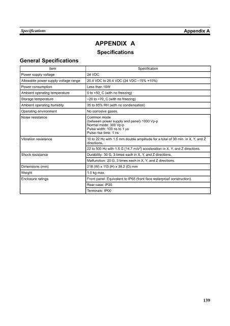
SpecificationsAppendix APerformance SpecificationsDisplay SpecificationsItemDot matrix liquidcrystal display panelNumber of dots(resolution)Effective display areaView angle Left direction: 35_Right direction: 35_Life expectancySpecification160 dots (vertically) x 64 dots (horizontally)100 mm (vertically) x 40 mm (horizontally)50,000 hours minimumLED Backlight Life expectancy 50,000 hours minimum (guaranteed time: 30,000 hours)IndicatorsPanel SpecificationsItemAutomatic turn-offPOWER indicator(Green LED)RUN indicator(Green LED)Can be set to turn off in 10 minutes or 1 hour, or to remain on.Lit while power is being supplied.Lit during operationSwitch Number of switches: 22Display CapacityDisplayelementsItemCharacter displaysCharacter stringdisplaysNumeral displaysGraph displaysNumeral settingsInput: Pressure-sensitive typeOperating force: 100 gf min.SpecificationLife expectancy: 1 million operations minimumSpecificationFixed character data (character strings registered for each screen)128 strings per file (20 bytes (20 normal characters) per string), 8 positions perscreen128 displays per file, 8 positions per screen, 8-digit display4 per screenDisplay of set numerical values 8 per screenScreen types Normal screen Displays screens registered as normal.Screen attributesMax. number of registered screens 250Screen registration methodScreen saving method(screen data memory)Numeral setting, password, display history recording, menu screenTransfer screen data created using the support tool to the NT11S.Saved to flash memory (recording format unique to NT11S)140
SpecificationsAppendix ADisplay Element SpecificationsItemDisplay charactersEnlargement functionCharacter display attributesSpecificationNormal characters (8 x 16 dots): Alphanumerics and symbolsMarks (16 x 16 dots): User-defined pictographsHorizontal magnificationsNormal, inverse, flashing, inverse flashingData QuantitiesStringsNumeral dataMarksItemSpecification128 strings comprising 20 characters each128 max. (8 digits each)64 marksSpecial FeaturesItemMaintenance functionsPassword screenMenu screenDaily report printingDisplay history recordingDisplay history printingSpecificationS Self-test functions for memory, switches, etc.S Function for checking settings such as communication conditionsS Communication check functionPassword designation when selecting a screenSetting: Set with the support toolNumber of password digits: 4Selecting screens with numeric keysSetting: Set with the support toolKeys used: Keys 1 through 4Number of destination screens: A maximum of four destination screenscan be set for one screen.The contents of a designated word are printed out at a printer in the specifiedformat.Setting: set with the support toolOutput trigger: 0 ! 1 status change of bit 4 of the PT status control areaThe history of display of the specified screen is recorded in memory and can beprinted out.Setting: Support toolOutput trigger: 0 ! 1 status change of bit 5 of the PT status control area141
SpecificationsAppendix ACommunications Specifications[For a Host Link]ItemSpecificationCommunications standardEIA RS-232C, RC-422ACommunications settingsStart-stop synchronizationBaud rate: 9600, 19,200 bpsData length: 7 bitsStop bit: 2 bitsParity: EvenConnector RS-232C 9-pin, D-SUB connector (male)RS-422A 4-pin terminal blockNumber of units connected1to1Transmission distanceMax. 15 m/RS-232C, Max. 500 m/RS-422ACommunications protocolC-series SYSWAY (1:N)[For an NT Link]ItemCommunications standardConnectorNumber of units connectedTransmission distance[For a Printer Port]EIA RS-232C9-pin, D-SUB connector (male)1to1Max. 15 mSpecificationItemCommunications standardConnectorNumber of units connectedTransmission distanceSpecificationCentronics25-pin D-SUB connector (female)1to1Max. 3 m142
SpecificationsAppendix APrinter Port Specifications[Printer Connector Pin Arrangement]1-STOROBE14-AUTO FDXT2DATA 015-ERROR3DATA 116-INIT4DATA 217-SLCTIN5DATA 318GROUND6DATA 419GROUND7DATA 520GROUND8DATA 621GROUND9DATA 722GROUND10-ACK23GROUND11BUSY24GROUND12PAPER EMPTY25GROUND13+SELECT[Signal Timing]The NT11S executes communication with a 2-wire handshake system using the STROBE signal and the ACK signal.DATASTROBEBUSYACKt1 t2 t3t1, t2 and t3 are each 0.5 "sec or longer.143
DimensionsAppendix BBody (NT11S-ST121)<strong>APPENDIX</strong> BDimensions203(7.99)113(4.45)98(3.86)218(8.58)7.5 (0.30)38.2(1.50)Unit : mm (inch)144
NT11S Installation EnvironmentAppendix C<strong>APPENDIX</strong> CNT11S Installation EnvironmentWhen installing the PT in the operation panel, observe the following points. See also the section “Getting Starting”.NoteS The view angle of the LCD screen is 35_ to the left and 35_ to the right. Install itat a position and height where operators will be able to see it well.S Do not install the unit at locations where the ambient temperature goes outsidetherange0to50_C or where the relative humidity goes outside the range 35 to85% RH.If the ambient temperature exceeds the range indicated above, install a fan oran air conditioner.LouvreFanPTControl panelS Provide sufficient space for ventilationS Do not install the unit directly above equipment that generates a lot of heat(heaters, transformers, large capacity resistors, etc.)S To ensure that the unit can be operated and maintained without difficulty, installit at a distance from high-voltage equipment and power equipment.S Install the unit as far as possible from personal computers, amateur radioequipment, radios, etc. The radio waves generated by the unit may cause interferencethat will affect these types of equipment.S Take the following points into account in order to prevent noise(1) Avoid installing the unit in panels in which high-voltage equipment is alsoinstalled.(2) Install the unit at a distance of at least 200 mm from power lines.Power line200 mm min.NT11S200 mm min.(3) If the unit is installed next to equipment that generates a strong electric ormagnetic field (solenoids, etc.), provide a gap of at least 40 mm.40 mm min.PTSolenoid145
Method for Making the Cable for Connection to the PCAppendix D<strong>APPENDIX</strong> DMethod for Making the Cable for Connection to the PCExplained below is the method for making the cable that connects the NT11S and the PC/Host.Connect the wires to the connectors in accordance with the connector specification for each unit.Making the Cable for Connection to the PC (RS-232C Type)Parts RequiredTwo connectors, two connector covers and one cable are required to make up a connecting cable. One connectorand one connector cover is supplied with most PCs.PCNT11S 1SName Model Delivered with RemarksConnectorXM2A-0901 CseriesCQM1 9-pin, manufactured by OMRONXM2A-2501 C200H-LK201 25-pin, manufactured by OMRONConnector XM2S-0911 CseriesCQM1 9-pin, manufactured by OMRONcover XM2S-2511 C200H-LK201 25-pin, manufactured by OMRONConnector XM2A-0901 — 9-pin, manufactured by OMRONConnectorcoverXM2S-0911 — 9-pin, manufactured by OMRONWhen connecting the NT11S to an OMRON PLC CjjH , the connector and the connector cover must be preparedseparately since they are not supplied with the CjjH.The connector provided in the CPU unit of the CjjH is a 9-pin connector. For the connection, the following connectorand connector hood should be prepared.S Connnector:XM2A-0901 (9-pin type, OMRON)S Connector cover: XM2S-0911 (9-pin type, OMRON)Prepare the cable recommended by OMRON.The recommended cables are indicated in the following table.CableName Type RemarkAWG28¢5PIFVV-SBCO-MA-VV-SB5P¢28AWGMulticonductor shielded cable (FUJIKURA, Ltd.)Multiconductor shielded cable (HITACHI Cable, Ltd.)146
Method for Making the Cable for Connection to the PCAppendix DConnecting an NT11S to a C-Series CQM1, C200HS Series CPUS C-Series CQM1, C200HS Series CPU Unit 9-pin Connector SpecificationsApplicable CPU:CQM1-CPU21-ECQM1-CPU41-ECQM1-CPU42-ECQM1-CPU43-ECQM1-CPU44-ES Electrical characteristics:S Signal direction:1 65S Wiring Connections9C200HS-CPU21-EC200HS-CPU23-EC200HS-CPU31-EC200HS-CPU33-EComplies with EIA RS-232CSignal input and output is relative to the PC.ConnectorPin No.Signal NameAbbreviationSignal DirectionConnector cover Frame ground FG -- --Input2 Send data SD (TXD) f3 Receive data RD (RXD) f4 Request to send RS (RTS) f5 Clear to send CS (CTS) f9 Signal ground SG (GND) -- --Either short the RS and CS pins of the PC connector together or set the CTS setting selector switch at the rearface of the host link unit to “0V” (see ∗ in the figure).OutputNT11SPC (host link unit)RS-232CinterfaceFGSDRDRSCS+5V----SGPinnumber123456789Shieldingwire∗PinnumberConnector cover2345------99-pin connectorAbbreviationAbbreviationFGSDRDRSCS------SGRS-232Cinterface149
Method for Making the Cable for Connection to the PCAppendix DMaking the Cable for Connection to the PC (RS-422A Type)Parts RequiredTwo connectors, two connector covers and one cable are required to make up a connecting cable. One connectorand one connector cover is supplied with most PCs.Name Model Delivered with RemarksConnectorXM2A-0901 CseriesCQM1 9-pin, manufactured by OMRONDE-9P C200H-LK202 9-pin, manufactured by JAEConnector XM2S-0911 CseriesCQM1 9-pin, manufactured by OMRONcover DE-C1-J6 C200H-LK202 9-pin, manufactured by JAEWhen connecting the NT11S to an OMRON PLC CjjH , the connector and the connector cover must be preparedseparately since they are not supplied with the CjjH.The connector provided in the CPU unit of the CjjH is a 9-pin connector. For the connection, the following connectorand connector hood should be prepared.S Connector:XM2A-0901 (9-pin type, OMRON)S Connector cover: XM2S-0911 (9-pin type, OMRON)Prepare the cable recommended by OMRON.The recommended cables are indicated in the following table.CableName Type RemarkH-9293A(CO-HC-ESV-3P × 7/0.2)For RS-422A (HIRAKAWA Hewtech Corp.)150
Method for Making the Cable for Connection to the PCAppendix DConnector Specifications and Wiring for OMRON Units (RS-422A Type)Connecting an NT11S to a C-Series Host Link UnitS C-Series Host Link Connector SpecificationsS Applicable Host Link Unit:S Electrical characteristics:S Signal direction:1 65 9S Wiring ConnectionsC200H-LK202 (-V1)Conform to EIA RS-422ASignal input and output is relative to the host link unit.ConnectorSignal NamePin No.Signal DirectionAbbreviationInput Output1 Receive data B RDB f3 Signal ground SG -- --5 Send data B SDB f6 Receive data A RDA f7 Frame ground FG -- --9 Send data A SDA fNT11SRS-422AterminalblockSDASDBRDARDBShielding wireRS-422A cablePC (host link unit)Pinnumber135679Connector coverAbbreviationAbbreviationRDBSGSDBRDAFGSDAFGRS-422Ainterface151
Method for Making the Cable for Connection to the PCAppendix DMaking the CableThe procedure to make up the cable is described below.Cable PreparationThe preparation of the cable differs according to whether or not the shielding wire is to be connected to the FG.S Cable with Shielding Wire Connected to FG(1) Cut the cable to the required length.(2) Remove the external vinyl insulation from the cable with a razor blade. Take care not to damage the shieldingunderneath.(3) Cut back the shielding wire with scissors.(4) Use wire strippers to strip the insulation from each wire.(5) Fold back the shielding wire.(6) Wrap aluminum foil tape around the folded-back shielding wire.(1)(2)(3)(4)40(1.57)(RS-232C)25(0.95)(RS-422A)10(0.39)5(0.19)(5)(6)Aluminum foil tape[Units: mm (in.)]152
Method for Making the Cable for Connection to the PCAppendix DS Cable with Shielding Wire Not Connected to FG(1) Cut the cable to the required length.(2) Remove the external vinyl insulation from the cable with a razor blade. Take care not to damage the shieldingunderneath.(3) Cut back the shielding wire with scissors.(4) Use wire strippers to strip the insulation from each wire.(5) Wrap vinyl tape over the cut off end of the shielding wire.(1)(2)40(1.57)(RS-232C)25(0.95)(RS-422A)(3)(4)5(0.19)(5)Soldering[Units: mm (in.)]Vinyl tape(1) Slide heat-shrink tube over each wire.(2) Pre-solder each wire and connector cable.(3) Solder each wire to the connector terminal.Soldering ironHeat-shrink tube(F, 1.5mm dia, l = 10mm)(4) Push the heat-shrink tube over the soldered joint and heat the tube to shrink it in place.Heat-shrink tube153
Method for Making the Cable for Connection to the PCAppendix DConnector Cover AssemblyAssemble the connector covers as shown in the diagram below.End connected to FGAluminum foil tapeEndnot connected to FG154
Making the Cable for Connection to the Support ToolAppendix E<strong>APPENDIX</strong> EMaking the Cable for Connection to the Support ToolThe wiring to be done depends on the type of RS-232C connector at the personal computer.S For a 25-pin connectorPersonal computerSDRDRSCSSGFG234571Shielding wire234591SDRDRSCSSGFGConnector for peripheraldevices on PT bodyThe table below indicates the recommended parts for making the connection cable.Name Model RemarksConnector XM2A-2501 25-pin, manufactured by OMRONXM2A-09019-pin (Plug), manufactured by OMRONConnector cover XM2S-2511 25-pin, manufactured by OMRONXM2S-09119-pin, manufactured by OMRONCableAWG28¢5PMulticore cable, manufactured by Fujikura, LtdIFVV-SBCO-MA-VV-SB5P¢28AWGMulticore cable, manufactured by Hitachi Cable, LtdS For a 9-pin connectorPersonal computerRDSDRSCSSG2378523459SDRDRSCSSGConnector for peripheraldevices on PT bodyShielding wire1FGThe table below indicates the recommended parts for making the connection cable.Name Model RemarksConnector XM2D-0901 9-pin (Socket), manufactured by OMRONXM2A-09019-pin (Plug), manufactured by OMRONConnector cover XM2S-0911 9-pin, manufactured by OMRONCableAWG28¢5PIFVV-SBCO-MA-VV-SB5P¢28AWGMulticore cable, manufactured by Fujikura, LtdMulticore cable, manufactured by Hitachi Cable, Ltd155
NT11S Internal ProcessingAppendix F<strong>APPENDIX</strong> FNT11S Internal ProcessingWhen host link/NT link is used, the following processing is executed inside the NT11S. Processing is divided intotwo types: periodic processing and event processing.Periodic ProcessingWhen the NT11S is in the RUN mode it executes the following internal processing cyclically. The contents of all theallocated bits and words used for screen display are read from the PC at one time, allowing high-speed processing.[NT11S processing]NT11S power ON[Details of processing]Initial processingHardware check, communication status check, etc.,executedOperation startInitial values written to the memory tablesScreen switching(PT!PC)When the values registered in the NT11S are used asthe initial values in the memory tables, these values arewritten into the allocated words of the PC.The allocated bits and words for the displayelements that have to be read from the PC areregistered in the PC.(PT!PC)Registration of the read allocated bits and words in thePCReading of allocated bits and words(PT#PC)The contents of the allocated bits and words registeredin the PC are all read at one time.Note- Only the data of the PC Status Control Area and data for currently displayedscreens is read from the PC.Even if the contents of the PC words allocated as memory tables are changed,the data are not upgraded at the NT11S unless these memory tables are usedfor screen displays.- The maximum number of bits/words that can be read is 120 words per screen.If the number that can be read is exceeded, the data are not upgraded.156
NT11S Internal ProcessingAppendix FEvent ProcessingWhen the status of the NT11S changes during operation, the processing for writing the changed data to the relevantarea of the PC memory is executed.This kind of processing is only executed when statuses change. When changes occur simultaneously, the processingsare executed in accordance with the order of priority.[NT11S processing][Details of processing]HighWriting to the PT status notify area(PT!PC)Writing to the PT status notify area in order to informthe PC of changes in the PT operating status.Order of priorityBit writingWriting to numeral memory tables(PT!PC)(PT!PC)Writing to bits in order to inform the PC that a touchswitch has been pressed.Changing the contents of words allocated to the PCwhen the value in a numeral memory table haschanged.LowWriting to character string memory tables(PT!PC)Changing the contents of words allocated to the PCwhen the value in a numeral memory table haschanged.NoteData is only written to PC bits and numeral/character string memory tables for elementsin screens currently being displayed. If the contents of numeral/characterstring memory tables that are not being displayed change, the changed contentsare not written to the PC.157
Model ListAppendix GPTModelNT11S-ST121NT11S-ST121BHost Link UnitBeigeBlack<strong>APPENDIX</strong> GModel ListSpecificationModel Specification Applicable PCC200H-LK101-PV1 Rack-mounting Unit with optical-fiber cable connector for C200H C-seriesC200H-LK201-V1 Rack-mounting Unit with RS-232C connector for C200H C200HC200H-LK202-V1 Rack-mounting Unit with RS-422C connector for C200HCPUs (For Connection Via a Host Link)CQM1-CPU21-ECQM1-CPU41-ECQM1-CPU42-ECQM1-CPU43-ECQM1-CPU44-EC200HS-CPU21-EC200HS-CPU23-EC200HS-CPU31-EC200HS-CPU33-EModel Specification PC TypeFeatures a 9-pin connector for RS-232C connectionsFeatures a connector for RS-232C connections(selectable/9-pin)CPUs (For Connection Via an NT Link)CQM1-CPU41-ECQM1-CPU42-ECQM1-CPU43-ECQM1-CPU44-EC200HS-CPU21-EC200HS-CPU23-EC200HS-CPU31-EC200HS-CPU33-EC-seriesCQM1C200HSName Model PC TypeFeatures a 9-pin connector for RS-232C connectionsFeatures a 9-pin connector for RS-232C connectionsRelated Parts and Equipment for PTName Model RemarksSupport Tool NT11S-ZA3AT-EV1 3.5 inch FD for NT11S seriesC-seriesCQM1C200HS158
Model ListAppendix GParts Used for ConnectionConnection cableAWG28¢5PIFVV-SBModelCO-MA-VV-SB5P¢28AWGH-9293A(CO-HC-ESV-3P¢7/0.2)RemarksMulticore cable, manufactured by Fujikura, Ltd.Multicore cable, manufactured by Hitachi Cable, Ltd.For RS-422A, manufactured by HIRAKAWA Hewtech Corp.Applicable connectorsName Model RemarkConnector XM2A-2501 25-pin, manufactured by OMRONXM2A-09019-pin (Plug), manufactured by OMRONDE-9P9-pin, manufactured by JAEConnector cover XM2S-2511 25-pin, manufactured by OMRONXM2S-09119-pin, manufactured by OMRONDE-C1-J69-pin, manufactured by JAE159
PC Memory MapAppendix H<strong>APPENDIX</strong> HPC Memory MapOMRON C-Series Memory MapArea IR Area HR Area AR AreaLink RelayAreaTimer/CounterAreaDM AreaLadder type C200H 0000 to 0255 0000 to 0099 0000 to 0027 0000 to 0063 0000 to 0511 0000 to 1999C200HS 0000 to 0511 0000 to 0099 0000 to 0027 0000 to 0063 0000 to 05110000 to 66557000 to 9999CQM1 0000 to 0255 0000 to 0099 0000 to 0027 0000 to 0063 0000 to 0051 0000 to 6655160
Special CharactersAppendix IEnglish Character Codes<strong>APPENDIX</strong> ISpecial CharactersPin 2 of SW2 must be ON to enable English language messages to use the following codes.Example: Hex code is represented by 30, decimal code by 48, and character by 0.30 048Code 20 and 32 in the table represents a space, as indicated by “SP”.Hex Digits 2- 3- 4- 5- 6- 7- 8- 9-1st2nd-0 20 SP 30 0 40 @ 50 P 60 ‘ 70 p 80 Ç 90 É32 48 64 80 96 112 128 144-1 21 ! 31 1 41 A 51 Q 61 a 71 q 81 ü 91 æ33 49 65 81 97 113 129 145-2 22 ” 32 2 42 B 52 R 62 b 72 r 82 é 92 Æ34 50 66 82 98 114 130 146-3 23 # 33 3 43 C 53 S 63 c 73 s 83 â 93 ô35 51 67 83 99 115 131 147-4 24 $ 34 4 44 D 54 T 64 d 74 t 84 ä 94 ö36 52 68 84 100 116 132 148-5 25 % 35 5 45 E 55 U 65 e 75 u 85 à 95 ò37 53 69 85 101 117 133 149-6 26 & 36 6 46 F 56 V 66 f 76 v 86 å 96 û38 54 70 86 102 118 134 150-7 27 ’ 37 7 47 G 57 W 67 g 77 w 87 ç 97 ù39 55 71 87 103 119 135 151-8 28 ( 38 8 48 H 58 X 68 h 78 x 88 ê 98 ÿ40 56 72 88 104 120 136 152-9 29 ) 39 9 49 I 59 Y 69 i 79 y 89 ë 99 Ö41 57 73 89 105 121 137 153-A 2A * 3A : 4A J 5A Z 6A j 7A z 8A è 9A Ü42 58 74 90 106 122 138 154-B 2B + 3B ; 4B K 5B [ 6B k 7B { 8B ï 9B ¢43 59 75 91 107 123 139 155-C 2C , 3C < 4C L 5C \ 6C l 7C | 8C î 9C £44 60 76 92 108 124 140 156-D 2D - 3D = 4D M 5D ] 6D m 7D } 8D ì 9D ¥45 61 77 93 109 125 141 157-E 2E . 3E > 4E N 5E ^ 6E n 7E ~ 8E Ä 9E Pt46 62 78 94 110 126 142 158-F 2F / 3F ? 4F O 5F _ 6F o 7F 8F Å 9F ƒ47 63 79 95 111 127 143 159161
Special CharactersAppendix IHex Digits1st2ndA- B- C- D- E- F--0 A0 á B0 C0 D0 E0 $ F0 %160 176 192 208 224 240-1 A1 í B1 C1 D1 E1 & F1 161 177 193 209 225 241-2 A2 ó B2 C2 D2 E2 ' F2 (162 178 194 210 226 242-3 A3 ú B3 C3 D3 E3 ) F3 *163 179 195 211 227 243-4 A4 ñ B4 C4 D4 E4 + F4 ,164 180 196 212 228 244-5 A5 Ñ B5 C5 D5 E5 - F5 .165 181 197 213 229 245-6 A6 a B6 C6 D6 E6 μ F6 /166 182 198 214 230 246-7 A7 o B7 C7 D7 E7 0 F7 1167 183 199 215 231 247-8 A8 ¿ B8 C8 D8 E8 2 F8 _168 184 200 216 232 248-9 A9 B9 C9 D9 E9 3 F9 .169 185 201 217 233 249-A AA BA CA DA EA 4 FA D170 186 202 218 234 250-B AB 1 / 2 BB CB DB EB 5 FB 6171 187 203 219 235 251-C AC 1 / 4 BC CC DC EC 7 FC n172 188 204 220 236 252-D AD ¡ BD CD DD ED ø FD 2173 189 205 221 237 253-E AE « BE CE DE EE 8 FE ∗174 190 206 222 238 254-F AF » BF CF DF EF 9 FF ∗175 191 207 223 239 255∗: Used as the prefix for mark data codes (2 bytes).162