

Retractable pH/ORP Sensors - Emerson Process Management
Retractable pH/ORP Sensors - Emerson Process Management
Retractable pH/ORP Sensors - Emerson Process Management

You also want an ePaper? Increase the reach of your titles
YUMPU automatically turns print PDFs into web optimized ePapers that Google loves.
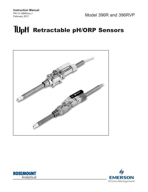
Instruction Manual<br />
PN 51-396R/rev.J<br />
February 2011<br />
Model 396R and 396RVP<br />
<strong>Retractable</strong> <strong>pH</strong>/<strong>ORP</strong> <strong>Sensors</strong>
ESSENTIAL INSTRUCTIONS<br />
READ THIS PAGE BEFORE PROCEEDING!<br />
Rosemount Analytical designs, manufactures, and tests its products to<br />
meet many national and international standards. Because these instruments<br />
are sophisticated technical products, you must properly install,<br />
use, and maintain them to ensure they continue to operate within their<br />
normal specifications. The following instructions must be adhered to and<br />
integrated into your safety program when installing, using, and maintaining<br />
Rosemount Analytical products. Failure to follow the proper<br />
instructions may cause any one of the following situations to occur: Loss<br />
of life; personal injury; property damage; damage to this instrument; and<br />
warranty invalidation.<br />
• Read all instructions prior to installing, operating, and servicing the<br />
product. If this Instruction Manual is not the correct manual, telephone<br />
1-800-654-7768 and the requested manual will be provided. Save this<br />
Instruction Manual for future reference.<br />
• If you do not understand any of the instructions, contact your<br />
Rosemount representative for clarification.<br />
• Follow all warnings, cautions, and instructions marked on and<br />
supplied with the product.<br />
• Inform and educate your personnel in the proper installation, operation,<br />
and maintenance of the product.<br />
• Install your equipment as specified in the Installation Instructions of<br />
the appropriate Instruction Manual and per applicable local and<br />
national codes. Connect all products to the proper electrical and<br />
pressure sources.<br />
• To ensure proper performance, use qualified personnel to install, operate,<br />
update, program, and maintain the product.<br />
• When replacement parts are required, ensure that qualified people<br />
use replacement parts specified by Rosemount. Unauthorized parts<br />
and procedures can affect the product’s performance and place the<br />
safe operation of your process at risk. Look alike substitutions may<br />
result in fire, electrical hazards, or improper operation.<br />
• Ensure that all equipment doors are closed and protective covers are<br />
in place, except while maintenance is being performed by qualified<br />
persons, to prevent electrical shock and personal injury.<br />
ATEX DIRECTIVE<br />
DANGER<br />
HAZARDOUS AREA INSTALLATION<br />
Installations near flammable liquids or in hazardous<br />
area locations must be carefully evaluated by qualified<br />
on site safety personnel. This sensor is not Intrinsically<br />
Safe or Explosion Proof.<br />
To secure and maintain an intrinsically safe installation,<br />
the certified safety barrier, transmitter, and sensor<br />
combi nation must be used. The installation system<br />
must comply with the governing approval<br />
agency (FM, CSA or BASEEFA/CENELEC) hazardous<br />
area classification requirements. Consult your<br />
analyzer/transmitter instruc tion manual for details.<br />
Proper installation, operation and servicing of this<br />
sensor in a Hazardous Area Instal lation is entirely<br />
the responsibility of the user.<br />
WARNING<br />
RETRACTABLE SENSORS<br />
<strong>Retractable</strong> sensors must not be inserted nor<br />
retracted when process pressures are in excess<br />
of 64 psig (542kPa) for option 21 or 35 psig<br />
(343 kPa) for option 25.<br />
CAUTION<br />
SENSOR/PROCESS APPLICATION COMPATIBILITY<br />
The wetted sensor materials may not be compatible<br />
with process com position and operating<br />
conditions. Application compat ibility is entirely<br />
the responsibility of the user.<br />
Special Conditions for safe use<br />
1. All <strong>pH</strong>/<strong>ORP</strong> sensors have a plastic enclosure which must only be cleaned with a damp cloth to avoid the danger due<br />
to a build up of an electrostatic charge.<br />
2. All <strong>pH</strong>/<strong>ORP</strong> sensor Models are intended to be in contact with the process fluid and may not meet the 500V r.m.s. a.c.<br />
test to earth. This must be taken into consideration at installation.<br />
About This Document<br />
This manual contains instructions for installation and operation of the Model 396R & 396RVP TU<strong>pH</strong><br />
<strong>Retractable</strong> <strong>pH</strong>/<strong>ORP</strong> <strong>Sensors</strong>. The following list provides notes concerning all revisions of this document.<br />
Rev. Level Date Notes<br />
A 1/96-1/01 This is the initial release of the product manual. The manual has been reformatted to reflect the<br />
<strong>Emerson</strong> documentation style and updated to reflect any changes in the product offering.<br />
B 7/02 Revised multiple drawings.<br />
C 8/02 Added drawing #40105549, rev. D.<br />
D 4/03 Revised drawing #40396R21/22 on page 18.<br />
E 8/03 Added Silcore information.<br />
F 9/04 Updated ordering info and added/revised wiring drawings.<br />
G 1/05 Delete obsolete options.<br />
H 1/07 Miscellaneous revisions.<br />
I 11/10 Removed mention of patents and updated dnv logo.<br />
J 2/11 Added ATEX directive and updated caution boxes per ANSI standard.
MODEL 396R <strong>pH</strong>/<strong>ORP</strong> TABLE OF CONTENTS<br />
MODEL 396R AND 396RVP<br />
RETRACTABLE <strong>pH</strong>/<strong>ORP</strong> SENSORS<br />
TABLE OF CONTENTS<br />
Section Title Page<br />
1.0 DESCRIPTION AND SPECIFICATIONS........................................................... 1<br />
1.1 Features and Applications................................................................................. 1<br />
1.2 Performance and Physical Specifications ......................................................... 2<br />
1.3 Ordering Information ......................................................................................... 3<br />
2.0 INSTALLATION ................................................................................................. 6<br />
2.1 Unpacking and Inspection................................................................................. 6<br />
2.2 Mechanical Installation ..................................................................................... 6<br />
3.0 WIRING MODEL 396R...................................................................................... 14<br />
4.0 WIRING MODEL 396RVP................................................................................. 23<br />
5.0 START UP AND CALIBRATION........................................................................ 30<br />
5.1 Start up.............................................................................................................. 30<br />
5.2 <strong>pH</strong> Calibration ................................................................................................... 30<br />
5.3 <strong>ORP</strong> Calibration ................................................................................................ 31<br />
6.0 MAINTENANCE ................................................................................................ 32<br />
6.1 Maintenance...................................................................................................... 32<br />
6.2 Sensor Removal................................................................................................ 32<br />
6.3 <strong>pH</strong> Electrode Cleaning ...................................................................................... 32<br />
6.4 Platinum Electrode Cleaning............................................................................. 33<br />
6.5 Automatic Temperature Compensation............................................................. 33<br />
6.6 Sensor Tube Replacement................................................................................ 33<br />
7.0 DIAGNOSTIC AND TROUBLESHOOTING ...................................................... 36<br />
7.1 Diagnostics and Troubleshooting with Model 54/3081 <strong>pH</strong>/<strong>ORP</strong> Diagnostics.... 36<br />
7.2 Troubleshooting without Diagnostics................................................................. 37<br />
8.0 RETURN OF MATERIAL................................................................................... 38<br />
LIST OF TABLES<br />
Table No. Title Page<br />
1-1 Commonly Used Accessories for Model 396R.................................................. 4<br />
1-2 Other Accessories for Model 396R ................................................................... 4<br />
1-3 Commonly Used Accessories for Model 396RVP ............................................. 5<br />
1-4 Other Accessories for Model 396RVP............................................................... 5<br />
5-1 <strong>ORP</strong> of Saturated Quinhydrone Solutions ........................................................ 31<br />
6-1<br />
6-2<br />
Ro and R1 Values for Temperature Compensation Elements...........................<br />
Temperature vs. Resistance of Auto T.C. Elements ..........................................<br />
33<br />
33<br />
7-1 Troubleshooting with Diagnostics...................................................................... 36<br />
7-2 Troubleshooting without Diagnostics................................................................. 37<br />
i
MODEL 396R <strong>pH</strong>/<strong>ORP</strong> TABLE OF CONTENTS<br />
LIST OF FIGURES<br />
Figure No. Title Page<br />
1-1 Cross Section Diagram of the TU<strong>pH</strong> Reference Technology ............................ 1<br />
2-1 Exploded View of Ball Valve Kit PN 23240-00 used with process connector .<br />
PN 23166-00 (or PN 23166-01) ........................................................................ 7<br />
2-2 Typical Mounting Configurations for Model 396R ............................................. 8<br />
2-3 Typical Mounting Configurations for Model 396RVP......................................... 8<br />
2-4 Dimensional Drawing — Model 396R with Optional Ball Valve PN 23765-00 .. 9<br />
2-5 Dimensional Drawing — Model 396R with Optional Ball Valve PN 23240-00 .. 10<br />
2-6 Dimensional Warning Label for Hemi Bulb <strong>Sensors</strong> and Sensor Diagram ....... 11<br />
2-7 Dimensional Drawing — Model 396RVP with Optional 1-1/2 inch Ball Valve ..<br />
PN 23240-00 ..................................................................................................... 12<br />
2-8 Dimensional Drawing — Model 396RVP with Optional 1-1/4 inch Ball Valve ..<br />
PN 23765-00 ..................................................................................................... 13<br />
3-1 Cable Preparation Instructions for Model 396R ................................................ 14<br />
3-2 Wiring Model 396R-54Model 54e, 81, 3081, 4081, 5081 <strong>pH</strong>/<strong>ORP</strong> ................... 15<br />
3-3 Wiring Model 396R-54 with Remote Junction Box & Preamp (PN 23555-00) ........ 15<br />
3-4 Wiring Model 396R-50 for use with Remote Junction Box (PN 23309-03)............. 16<br />
3-5 Wiring Model 396R-54 for use with Remote Junction Box (PN 23309-04)............. 16<br />
3-6 Wiring Model 396R-54 to Model 1181 <strong>pH</strong>/<strong>ORP</strong> ................................................... 17<br />
3-7 Wiring Model 396R-54 to Models 1054A/B <strong>pH</strong>/<strong>ORP</strong>, 2054 <strong>pH</strong>, and 2081 ............. 17<br />
3-8 Wiring Model 396R-54 to Model SCL-(P/Q)......................................................... 18<br />
3-9 Wiring Model 396R-54-61 to Model Xmt-P-HT-10.................................................... 18<br />
3-10 Wiring Model 396R-50/54-60 for use with Sensor Head J-Box......................... 19<br />
3-11 Wiring Model 396R-54-61 for use with Sensor Head J-Box.............................. 19<br />
3-12 Wiring Model 396R-50 for use with J-Box (PN 23707-00) to Models 1181, .....<br />
1050, 1060, 1030, 1023 <strong>pH</strong> Transmitters ......................................................... 20<br />
3-13 Wiring Model 396R-54 for use with J-Box (PN 23708-01) to Models 1054, .....<br />
2054, and 2081 <strong>pH</strong> Transmitters....................................................................... 21<br />
3-14 Wiring Model 396R-( )-54 to Model 1055-10-22-32 .......................................... 22<br />
3-15 Wiring Model 396R-54-61 to Model 1055-10-22-32.......................................... 22<br />
4-1 Wire Functions and Pin Connections for Model 396RVP.................................. 23<br />
4-2 Wiring Model 396RVP to Model 81 ................................................................... 24<br />
4-3 Wiring Model 396RVP to Model 1181 ............................................................... 24<br />
4-4 Wiring Model 396RVP to Model 81 thru a Remote J-Box ................................. 24<br />
4-5 Wiring Model 396RVP to Models 1181/1050/1060/1003/1023 thru Remote J-Box 24<br />
4-6 Wiring Model 396RVP to Model 2081 ............................................................... 25<br />
4-7 Wiring Model 396RVP to Models 3081, 4081, and 5081 .................................. 25<br />
4-8 Wiring Model 396RVP to Model 2081 thru a Remote J-Box ............................. 25<br />
4-9 Wiring Model 396RVP to Models 3081, 4081, and 5081 thru a Remote J-Box 25<br />
4-10 Wiring Model 396RVP to Model 1054 ............................................................... 26<br />
4-11 Wiring Model 396RVP to Models 1054A/B and 2054........................................ 26<br />
4-12 Wiring Model 396RVP to Model 1054 thru a Remote J-Box ............................. 26<br />
4-13 Wiring Model 396RVP to Models 1054A/B and 2054 thru a Remote J-Box...... 26<br />
4-14 Wiring Model 396RVP to Model 54 and 54e ..................................................... 27<br />
4-15 Wiring Model 396RVP to Model 54 thru a Remote J-Box ................................. 27<br />
4-16 Wiring Model 396RVP to Model 2700 ............................................................... 27<br />
4-17 Wiring Model 396RVP to Model SCL-(P/Q) ...................................................... 27<br />
4-18 Wiring Model 396RVP to Model Xmt-P-HT-10 .................................................. 28<br />
4-19 Wiring Model 396RVP to Model 1055<strong>pH</strong>/<strong>pH</strong>..................................................... 28<br />
4-20 Wiring Model 396RVP to Model 1055<strong>pH</strong>/<strong>pH</strong> thru a Remote J-Box................... 28<br />
4-21 Wiring Model 396RVP to Model 1055-10-22-32................................................ 29<br />
6-1 Sensor Tube Replacement................................................................................ 35<br />
6-2 Male Connector Tightening Diagram................................................................. 35<br />
ii
MODEL 396R <strong>pH</strong>/<strong>ORP</strong> SECTION 1.0<br />
DESCRIPTION AND SPECIFICATIONS<br />
SECTION 1.0<br />
DESCRIPTION AND SPECIFICATIONS<br />
1.1 FEATURES AND APPLICATIONS<br />
The Model 396R and 396RVP <strong>Sensors</strong> are specifically<br />
designed for improved life in harsh, dirty applications where<br />
a separate sample stream is difficult to provide and greater<br />
insertion depths are required. Model 396R is designed for<br />
use with a 1-1/4 in. or 1-1/2 in. ball valve for hot tap installation.<br />
The Model 396R is constructed of molded polypropylene<br />
housed in a titanium tube with EPDM seals to provide maximum<br />
chemical resistance 2,3 .<br />
Model 396R also features a titanium solution ground for<br />
advanced sensor diagnostics when used with the Models<br />
1055, Xmt-P, 54e, 81, 3081, or 5081 <strong>pH</strong>/<strong>ORP</strong> Analyzer/<br />
Transmitter. Advanced sensor diagnostics provide preventative<br />
maintenance by notifying the operator for replacement<br />
and cleaning of an aged or fouled sensor for continuous<br />
optimum performance.<br />
The sensor also features a shrouded tip for protection from<br />
breakage while allowing process to flow by the glass electrode<br />
for accurate and reliable <strong>pH</strong> measurement.<br />
The Model 396R is available without an integral preamplifier<br />
only and 15 ft or 9.5 in. of integral high quality 9 conductor<br />
cable. The preamplifier must be housed in a remote location<br />
or in a J-Box kit for attachment at the rear, cable end of the<br />
sensor (order separately) or integral to the Analyzer/<br />
Transmitter. The Model 396R is compatible with all<br />
Rosemount Analytical and various other manufacturers<br />
instruments.<br />
The entire line of TU<strong>pH</strong> model sensors now incorporate<br />
the new SILCORE 1 technology contaminant barrier. This<br />
triple-seal barrier prevents moisture and material impurities<br />
from migrating to the <strong>pH</strong> sensor’s reference electrode’s metal<br />
lead wire. By preventing these contaminants from compromising<br />
the integrity of the <strong>pH</strong> measurement, sensor life is<br />
increased, especially at higher temperatures where<br />
increased migrations occur. In addition, the SILCORE technology<br />
provides added protection against sensor failure due<br />
to vibrations and shock by transferring damaging energy<br />
away from the glass-to-metal seal.<br />
Model 396RVP: Rosemount Analytical has recently released<br />
Model 396RVP. This model has identical performance and<br />
physical specifications to the Model 396R (see Section 1.2)<br />
with the following exception: the Model 396RVP has a<br />
Variopol (VP) connector on the back end of the sensor in<br />
place of a cable.<br />
1 Silcore is a trademark of Rosemount Analytical.<br />
FIGURE 1-1. Cross Section Diagram of the TU<strong>pH</strong> Reference Technology<br />
All TU<strong>pH</strong> sensors are designed with a large area reference junction, helical reference pathway, and an AccuGlass <strong>pH</strong><br />
glass bulb. This sensor technology ensures superior performance while only requiring minimal maintenance.<br />
1
MODEL 396R <strong>pH</strong>/<strong>ORP</strong> SECTION 1.0<br />
DESCRIPTION AND SPECIFICATIONS<br />
1.2 PERFORMANCE AND PHYSICAL SPECIFICATIONS<br />
MODEL 396R<br />
Measured Range:<br />
<strong>ORP</strong>: -1500 to 1500mV<br />
<strong>pH</strong>: 0 to 14<br />
Percent Linearity Over <strong>pH</strong> Range:<br />
Hemi Bulb Flat Bulb<br />
0-2 <strong>pH</strong> 94% 93%<br />
2-12 <strong>pH</strong> 99% 98%<br />
12-13 <strong>pH</strong> 97% 95%<br />
13-14 <strong>pH</strong> 92% —<br />
Wetted Materials: Polypropylene, EPDM, titanium,<br />
glass, (platinum: <strong>ORP</strong> only)<br />
<strong>Process</strong> Connections: 1-1/2 or 1-1/4 in. with ball<br />
valve, 1 in. without ball valve<br />
Cable: Integral 15 ft or 9.5 in. 9 conductor cable<br />
except option 60 (9.5 in. coaxial cable with<br />
BNC) Recommended Interconnect (PN<br />
9200273)<br />
Maximum <strong>Process</strong> Pressure and Temperature:<br />
Hemi bulb: 150 psig (1136 kPa abs) at 212°F<br />
(100°C )<br />
Flat bulb: 100 psig (790 kPa abs) at 212°F<br />
(100°C )<br />
Maximum Pressure at Retraction or Insertion:<br />
Code 21: 64 psig (542 kPa abs)<br />
Code 25: 35 psig (343 kPa abs)<br />
Minimum Conductivity: 100 µS/cm<br />
Weight/Shipping Weight:<br />
Sensor:<br />
Code 21: 2.0 lb/3.0 lb (.9 kg/1.40 kg)<br />
Code 25: 3.0 lb/4.0 lb (1.40 kg/1.80 kg)<br />
Ball Valve:<br />
PN 23240-00; 5 lb/7 lb (2.25 kg /3.20 kg)<br />
PN 23634-00 8 lb/10 lb (3.65 kg/4.55 kg)<br />
J-Box: 3 lb/4 lb (1.40 kg/1.80 kg)<br />
2<br />
MODEL 396RVP<br />
Measured Range:<br />
<strong>ORP</strong>: -1500 to 1500mV<br />
<strong>pH</strong>: 0 to 14<br />
Available <strong>pH</strong> glass types: GPLR hemi bulb or flat bulb<br />
Wetted Materials: Polypropylene, EPDM, titanium,<br />
glass, (platinum: <strong>ORP</strong> only)<br />
<strong>Process</strong> Connections: none, use 1-inch process connector<br />
or ball valve kit (1-1/2 inch or 1-1/4 inch)<br />
Temperature Range: 0 to 100C (32 to 212F)<br />
Pressure Range (hemi bulb): 100-1136 kPa abs<br />
(0-150 psig)<br />
Pressure Range (flat bulb): 100-790 kPa abs<br />
(0-100 psig)<br />
Maximum Pressure at Retraction or Insertion:<br />
Code 21: 64 psig (542 kPa abs)<br />
Code 25: 35 psig (343 kPa abs)<br />
Minimum Conductivity: 75 µS/cm, nominal<br />
Preamplifier options: remote<br />
Weight/Shipping Weight:<br />
Sensor: Code 21: 2.0 lb/ 3.0 lb (.9 kg/1.40 kg)<br />
Code 25: 3.0 lb/4.0 lb (1.40 kg/1.80 kg)<br />
Ball Valve: PN 23240-00; 5 lb/7 lb (2.25 kg /3.20 kg)
MODEL 396R <strong>pH</strong>/<strong>ORP</strong> SECTION 1.0<br />
DESCRIPTION AND SPECIFICATIONS<br />
1.3 ORDERING INFORMATION<br />
The Model 396R Sensor is housed in a titanium tube, with a polypropylene reference junction and titanium solution<br />
ground for use with a ball valve (order separately) for hot tap applications. The sensor is available with either<br />
a hemi or flat glass <strong>pH</strong> electrode and features a shrouded glass/platinum electrode and PT100 or 3K temperature<br />
compensation. The 396R is available with 9.5 in. or 15 ft of integral cable. The 396R sensor is not available with<br />
a preamp. Junction box kits with preamps must be ordered separately if the analyzer/transmitter does not have<br />
an integral preamp within 15 ft. of the probe. <strong>Process</strong> connector and ball valve assemblies must also be ordered<br />
separately.<br />
MODEL<br />
396R TU<strong>pH</strong> RETRACTABLE <strong>pH</strong> SENSOR<br />
CODE MEASURING ELECTRODE TYPE (Required Selection)<br />
10 GPLR hemi glass, General Purpose Low Resistivity<br />
12 <strong>ORP</strong><br />
13 GPLR flat glass, General Purpose Low Resistivity<br />
CODE SENSOR LENGTH<br />
21 21 in. Titanium Tube<br />
25 36 in. Titanium Tube<br />
CODE ANALYZER/TC COMPATIBILITY (Required Selection)<br />
50 For Models 1181 (3K TC)<br />
54 For Models 1054B, 1055, 2081,54e, 81, 3081, 4081, 5081, Xmt, SCL-(P/Q), (PT 100 RTD)<br />
CODE OPTIONAL OPTIONS<br />
60 9.5 in. Cable with BNC (for use with Model 1181, 1054 series, 2054, 2081 Sensor Head J-Boxes)<br />
61 9.5 in. Cable no BNC (Not Valid w/Option 50) (for use with Model 54e, 1055, 81, 3081, 4081, 5081, Xmt<br />
Sensor Head J-Boxes)<br />
396R - 10 - 21 - 54 EXAMPLE<br />
The Model 396RVP ball valve retractable sensor features a gel-filled electrolyte solution with the large area,<br />
coating resistant TU<strong>pH</strong> polypropylene reference junction and a standard hemi or optional flat glass bulb. Model<br />
396RVP is housed in a Titanium sensor tube and can be mounted directly into the process using a 1 in. MNPT<br />
threaded process connector and a ball valve assembly kit (both ordered separately). It is offered with the watertight<br />
Variopol sensor-to-cable connector and uses the mating connector cable (ordered separately). Also available<br />
is a choice of temperature element, 3 K Balco or Pt 100 RTD. A remote preamplifier found in the<br />
analyzer/transmitter or in a junction box (ordered separately) must be used with this sensor for a reliable signal<br />
transmission.<br />
MODEL<br />
396RVP TU<strong>pH</strong> RETRACTABLE <strong>pH</strong>/<strong>ORP</strong> SENSOR<br />
CODE MEASURING ELECTRODE TYPE (Required Selection)<br />
10 Hemi bulb, General Purpose Low Resistivity<br />
12 <strong>ORP</strong><br />
13 Flat, GPLR glass<br />
CODE SENSOR LENGTH (Required Selection)<br />
21 21 in. Titanium Tube<br />
25 36 in. Titanium Tube<br />
CODE ANALYZER/TC COMPATIBILITY (Required Selection)<br />
50 For Models 1181 (3K TC)<br />
54 For Models 1054B, 1055, 2081,54e, 81, 3081, 4081, 5081, Xmt, SCL-(P/Q), (Pt 100 RTD)<br />
396RVP - 10 - 21 - 54 EXAMPLE<br />
3
MODEL 396R <strong>pH</strong>/<strong>ORP</strong> SECTION 1.0<br />
DESCRIPTION AND SPECIFICATIONS<br />
TABLE 1-1. COMMONLY USED ACCESSORIES FOR MODEL 396R<br />
For first time installations, Rosemount Analytical recommends using the following guide<br />
1. <strong>Retractable</strong> Mounting<br />
A. Choose one (required for all first time installations):<br />
PN 23166-00, 1 in. x 1 in. NPT process connector, 316 SST<br />
PN 23166-01, 1 in. x 1 in. NPT process connector, Titanium<br />
B. Choose one:<br />
PN 23240-00, 1-1/2 in. ball valve assembly, 316 SST<br />
PN 23765-00, 1-1/4 in. ball valve assembly, 316 SST<br />
2. Junction Boxes (Optional; Choose either Sensor Head or Remote)<br />
A. Sensor Head Junction Boxes (used with options -60 or -61 sensor) - Choose one:<br />
PN 23709-00; includes preamplifier for Models 54e, 81, 3081, 4081, 5081, Xmt, 1055<br />
PN 23708-01; includes preamplifier for Models 1054 series, 2054, 2081<br />
PN 23707-00; includes preamplifier for Model 1181<br />
B. Remote Junction Boxes (used with standard 15 ft. cable length sensor) - Choose one:<br />
PN 23555-00; includes preamplifier for Models 54e, 81, 3081, 4081, 5081, Xmt, 1055<br />
PN 23309-03; includes preamplifier for Model 1181<br />
PN 23309-04; includes preamplifier for Models 1054 series, 2054, 2081<br />
3. BNC Adapter - Choose one:<br />
PN 9120516, BNC Adapter for use with remote junction boxes PN’s 23309-03 and 23309-04<br />
Order option -60 (standard with BNC connector) for PN 23707-00 or 23708-01 sensor head junction boxes<br />
4. Extension Cables - Choose one:<br />
PN 23646-01, 11 conductor, shielded, prepped<br />
PN 9200273, 11 conductor, shielded, unprepped<br />
TABLE 1-2. OTHER ACCESSORIES FOR MODEL 396R<br />
4<br />
PART DESCRIPTION<br />
22698-00 Preamplifier plug-in for J-box, for Model 1003,<br />
22698-02 Preamplifier plug-in for J-box, for Models 1181/1050<br />
22698-03 Preamplifier plug-in for J-box, for Models 1054A/B, 2054, 2081<br />
23550-00 Remote Junction box with extension board<br />
9550167 O-ring, 2-214, EPDM for process connector<br />
9210012 Buffer solution, 4.01 <strong>pH</strong>, 16 oz<br />
9210013 Buffer solution, 6.86 <strong>pH</strong>, 16 oz<br />
9210014 Buffer solution, 9.18 <strong>pH</strong>, 16 oz<br />
22743-01 Pt100 preamp for Model 1181<br />
22744-01 3K Preamp for Model 1181<br />
23557-00 Preamplifier for junction box for Models 1055, 54e, 81, 3081, 4081, 5081, Xmt
MODEL 396R <strong>pH</strong>/<strong>ORP</strong> SECTION 1.0<br />
DESCRIPTION AND SPECIFICATIONS<br />
TABLE 1-3. COMMONLY USED ACCESSORIES FOR MODEL 396RVP<br />
FOR FIRST TIME 396RVP AND 398RVP INSTALLATIONS, ROSEMOUNT ANALYTICAL RECOMMENDS USING THE FOLLOWING GUIDE:<br />
1. Variopol Cable (required for all first time installations)<br />
Choose one: PN 23645-06, 15 ft cable with mating VP connector, prepped with BNC on analyzer end<br />
PN 23645-07, 15 ft cable with mating VP connector, prepped without BNC on analyzer end*<br />
2. <strong>Retractable</strong> Mounting<br />
1A. Choose one (required for all first time installations, except as noted):<br />
PN 23166-00 1 in. x 1 in. NPT process connector, 316 SST<br />
PN 23166-01 1 in. x 1 in. NPT process connector, Titanium<br />
Choose one (optional process connector o-rings):<br />
PN 9550220, Kalrez ®1 o-ring, 2-214<br />
PN 9550099, Viton ®1 o-ring, 2-214<br />
1B. Choose one:<br />
PN 23240-00 1-1/2 in. ball valve assembly, 316 SST<br />
PN 23765-00 1-1/4 in. ball valve assembly, 316 SST (process connector not needed)<br />
3. Remote Junction Boxes (Optional)<br />
Choose one: PN 23555-00 includes preamplifier for Models 54e, 81, 3081, 4081, 1055, 5081, Xmt<br />
PN 23309-03 and PN 22698-02 plug-in preamplifier for Model 1181Analyzer<br />
PN 23309-04 and PN 22698-03 plug-in preamplifier for Models 1054 series and 2081 Analyzers<br />
4. Extension cables<br />
Choose one: PN 23646-01, 11 conductor, shielded, prepped<br />
PN 9200273, 11 conductor, shielded, unprepped<br />
* Used for connections to Models 1181, 2081, 54e, 81, 3081, 4081, 5081, Xmt, 1055, and remote junction box PN 23555-00.<br />
2 kalrez and Viton are registered trademarks of DuPont Performance Elastomers.<br />
TABLE 1-4. OTHER ACCESSORIES FOR MODEL 396RVP<br />
PART DESCRIPTION<br />
22698-00 Preamplifier plug-in for junction box, for Model 1003,<br />
22698-02 Preamplifier plug-in for junction box, for Models 1181, 1050<br />
22698-03 Preamplifier plug-in for junction box, for Models 1054B, 2081<br />
22743-01 Pt100 preamplifier for Model 1181<br />
22744-01 3K Preamplifier for Model 1181<br />
23557-00 Preamplifier for junction box for Models 54e, 81, 3081, 4081, 5081, Xmt, 1055<br />
33046-00 Ferrule, 1 in., split 316SS<br />
9310096 Nut, swage, 1 in. 316SST<br />
9210012 Buffer solution, 4.01 <strong>pH</strong>, 16 oz<br />
9210013 Buffer solution, 6.86 <strong>pH</strong>, 16 oz<br />
9210014 Buffer solution, 9.18 <strong>pH</strong>, 16oz<br />
R508-80Z <strong>ORP</strong> solution, 460 mv ± 10 at 20°C<br />
9550167 EPDM O-ring for <strong>Process</strong> Connector (PN 23166-00 or 23166-01)<br />
12707-00 Jet Spray Cleaner<br />
5
MODEL 396R <strong>pH</strong>/<strong>ORP</strong> SECTION 2.0<br />
INSTALLATION<br />
2.1 UNPACKING AND INSPECTION. Inspect the outside<br />
of the carton for any damage. If damage is detected,<br />
contact the carrier immediately. Inspect the instrument<br />
and hardware. Make sure all items in the packing list<br />
are present and in good condition. Notify the factory if<br />
any part is missing.<br />
6<br />
NOTE<br />
If the sensor is to be stored, the protective<br />
boot should be filled with either KCl electrolyte<br />
solution or <strong>pH</strong> 4.0 buffer solution<br />
and replaced on sensor tip until ready to<br />
use.<br />
NOTE<br />
Save the original packing cartons and<br />
materials as most carriers require proof of<br />
damage due to mishandling, etc. Also, if it<br />
is necessary to return the instrument to the<br />
factory, you must pack the instrument in the<br />
same manner as it was received. Refer to<br />
Section 8.0 for instructions.<br />
WARNING<br />
Glass electrode must be wetted at all times (in storage<br />
and in line) to maximize sensor life.<br />
2.2 MECHANICAL INSTALLATION. The Model 396R<br />
Sensor may be installed through a weldalet or in a pipe<br />
tee or “Y”, as shown in Figure 2-1, when used with a<br />
ball valve. Insert the end of the sensor to a depth<br />
sufficient to ensure that the glass bulb is continuously<br />
wetted by the process fluid. The Model 396R can also<br />
be inserted directly into the process without the use of<br />
a ball valve for appli cations not requiring continuous<br />
operation during sensor maintenance.<br />
CAUTION<br />
Allow sufficient room for safe retraction and insertion of<br />
the sensor. Personnel should have room for stable footing<br />
while performing removal or insertion of the sensor.<br />
SECTION 2.0<br />
INSTALLATION<br />
The sensor must be mounted within 10-90 degrees of<br />
the horizontal with the tip pointed downward, thus<br />
keeping air bubbles off of the <strong>pH</strong> sensitive glass bulb.<br />
Bubbles settled on the glass bulb disrupt the electrical<br />
continuity between the <strong>pH</strong> sensitive glass and the silver/silver<br />
chloride measuring element.<br />
If the retraction version is to be installed without a ball<br />
valve follow the installation procedure for insertion<br />
service (Section 2.2.2). Perform the following steps for<br />
sensor installation through a ball valve:<br />
2.2.1 INSTALLATION THROUGH BALL VALVE.<br />
1. Carefully remove the liquid filled rubber boot which<br />
protects the glass electrode and keeps the liquid<br />
junction wet during shipping and storage. Discard<br />
the liquid and boot. Make sure the lubricated<br />
O-ring is in place in the groove inside the male<br />
connector on the sensor body.<br />
CAUTION<br />
Buffer solution, in the protective boot, may cause skin<br />
or eye irritation.<br />
2. With the male connector on the sensor’s body,<br />
insert the sensor into the ball valve until it gently<br />
touches the closed valve. The molded electrode<br />
guard will protect the glass bulb from breakage.<br />
3. Thread the male connector body tightly into the<br />
ball valve assembly. DO NOT tighten the hex nut<br />
on the male connector body; doing so would not<br />
allow the sensor to be inserted through the ball<br />
valve.<br />
4. Pull back hard on the sensor assembly, as if trying<br />
to remove the sensor, to be certain that the sensor<br />
cannot come free of the ball valve assembly. The<br />
built-in retraction stop will butt against the shoulder<br />
of the male connector if properly installed.<br />
CAUTION<br />
The sensor must be captured by the valve assembly<br />
and the male connector so that it cannot be blown<br />
free by process pressure if mishandled during insertion<br />
or retraction.<br />
5. After confirming that the sensor assembly is properly<br />
secured by the valve assembly, the valve may<br />
be opened and the sensor positioned into the<br />
process at the desired depth and orientation.
MODEL 396R <strong>pH</strong>/<strong>ORP</strong> SECTION 2.0<br />
INSTALLATION<br />
6. While holding the sensor in position, tighten the hex<br />
nut of the male connector to firmly secure the sensor<br />
in place. When the hex nut is tightened, the Teflon<br />
ferrule inside the compression fitting clamps the sensor<br />
tube.<br />
CAUTION<br />
Over tightening the hex nut may damage the ferrule.<br />
NOTE<br />
A stainless steel ferrule is available if the<br />
Teflon ferrule does not inadequately grip.<br />
When using the metallic ferrule, care must be<br />
taken to avoid over tightening and damaging<br />
the sensor tube. If the male connector leaks<br />
during insertion or retraction, replace the Oring<br />
in the male connector.<br />
2.2.2 INSTALLATION WITHOUT A BALL VALVE. The<br />
Model 396R Sensor may be installed through a weldalet<br />
or pipe tee or “Y” when used with a process connector<br />
(PN 23166-00 or 23166-01). The sensor should be<br />
installed within 80° of vertical, with the electrode facing<br />
down.<br />
FIGURE 2-1. Exploded View of Ball Valve Kit PN 23240-00<br />
used with process connector PN 23166-00 (or PN 23166-01)<br />
7
MODEL 396R <strong>pH</strong>/<strong>ORP</strong> SECTION 2.0<br />
INSTALLATION<br />
8<br />
JUNCTION BOX IS OPTIONAL<br />
FIGURE 2-2. Typical Mounting Configurations for Model 396R<br />
FIGURE 2-3. Typical Mounting Configurations for Model 396RVP
MODEL 396R <strong>pH</strong>/<strong>ORP</strong> SECTION 2.0<br />
INSTALLATION<br />
INCH<br />
MILLIMETER<br />
FIGURE 2-4. Dimensional Drawing — Model 396R with Optional Ball Valve PN 23765-00<br />
Note: Add five (5) inches to dimension A if mounting a sensor head junction box onto the sensor.<br />
9
MODEL 396R <strong>pH</strong>/<strong>ORP</strong> SECTION 2.0<br />
INSTALLATION<br />
10<br />
WHEN INCH AND METRIC DIMS<br />
ARE GIVEN<br />
MILLIMETER<br />
INCH<br />
DWG. NO. REV.<br />
40396R05 D<br />
FIGURE 2-5. Dimensional Drawing — Model 396R with Optional Ball Valve PN 23240-00<br />
Note: Add five (5) inches to dimension A if mounting a sensor head junction box onto the sensor.
MODEL 396R <strong>pH</strong>/<strong>ORP</strong> SECTION 2.0<br />
INSTALLATION<br />
MILLIMETER<br />
INCH<br />
36” 36”<br />
4.920<br />
Front Side 396R-21<br />
Note: Retraction Pressure<br />
Back Side 396R<br />
Front Side 396R-25<br />
Note: Retraction Pressure A<br />
MM / IN<br />
548.64 / 21.60<br />
916.94 / 36.10<br />
FIGURE 2-6. Dimensional Warning Label for Model 396R Hemi Bulb <strong>Sensors</strong> and Sensor Diagram<br />
Note: Pressure rating for flat glass sensors is 100-790 kPa (0-100 psig).<br />
2.25<br />
OPTION<br />
21<br />
25<br />
11
MODEL 396R <strong>pH</strong>/<strong>ORP</strong> SECTION 2.0<br />
INSTALLATION<br />
12<br />
WHEN INCH AND METRIC DIMS<br />
ARE GIVEN<br />
MILLIMETER<br />
INCH<br />
FIGURE 2-7. Dimensional Drawing — Model 396RVP with Optional 1-1/2 inch Ball Valve PN 23240-00
MODEL 396R <strong>pH</strong>/<strong>ORP</strong> SECTION 2.0<br />
INSTALLATION<br />
INCH<br />
MILLIMETER<br />
FIGURE 2-8. Dimensional Drawing — Model 396RVP with Optional 1-1/4 inch Ball Valve PN 23765-00<br />
13
MODEL 396R <strong>pH</strong>/<strong>ORP</strong> SECTION 3.0<br />
WIRING MODEL 396R<br />
WIRING MODEL 396R.<br />
Make electrical connections as shown on Figures 3-1<br />
through 3-15 using the following guidelines. For wiring<br />
Model 396RVP, see Section 4.0.<br />
1. Pay particular attention to the analyzer or transmitter<br />
model number when following details on the<br />
wiring diagrams to ensure that the connections are<br />
made to the proper terminals.<br />
2. Use Rosemount custom cable Part Number<br />
9200273 for interconnect.<br />
3. The maximum distance from the sensor to the<br />
analyzer is 15 ft without an integral preamplifier.<br />
14<br />
SECTION 3.0<br />
WIRING MODEL 396R<br />
4. Signal cable should be run in a dedicated conduit<br />
and should be kept away from AC power lines.<br />
NOTE<br />
For maximum EMI/RFI protection when wiring<br />
from the sensor to the junction box, the outer<br />
braid of the sensor should be connected to the<br />
outer braided shield of the extension cable.<br />
The outer braid of the extension cable to the<br />
instrument must be terminated at earth ground<br />
or by using an appropriate metal cable gland<br />
fitting, that provides a secure connection to the<br />
instrument cable.<br />
FIGURE 3-1. Cable Preparation Instructions (PN 9200274)<br />
WARNING: IF INNER BLACK<br />
CONDUCTIVE SHEATH IS IN<br />
CONTACT WITH THE EXPOSED<br />
LEADS, OR IS NOT PREPARED<br />
PROPERLY, IT MAY CAUSE AN<br />
ELECTRICAL SHORT.<br />
DWG. NO. REV.<br />
40396R24 A
MODEL 396R <strong>pH</strong>/<strong>ORP</strong> SECTION 3.0<br />
WIRING MODEL 396R<br />
FIGURE 3-2. Wiring Model 396R-54 to Models 54e, 81, 3081, 4081, and 5081 <strong>pH</strong>/<strong>ORP</strong><br />
WHEN INCH AND METRIC DIMS<br />
ARE GIVEN<br />
MILLIMETER<br />
INCH<br />
MODELS<br />
54e, 81, 3081,<br />
4081, 5081<br />
DWG. NO. REV.<br />
40396R07 D<br />
DWG. NO. REV.<br />
40396R08 B<br />
FIGURE 3-3. Wiring Model 396R-54 with Remote J-Box and Preamp (PN 23555-00)<br />
15
MODEL 396R <strong>pH</strong>/<strong>ORP</strong> SECTION 3.0<br />
WIRING MODEL 396R<br />
16<br />
DWG. NO. REV.<br />
40396R011 A<br />
FIGURE 3-4. Wiring Model 396R-50 for use with Remote Junction Box (PN 23309-03)<br />
1<br />
PREP ORANGE WIRE FOR PREAMP<br />
WITH BNC ADAPTER (PN 9120516).<br />
1<br />
DANGER:<br />
Do not connect sensor<br />
cable to power lines.<br />
Serious injury may result.<br />
DANGER:<br />
Do not connect sensor<br />
cable to power lines.<br />
Serious injury may result.<br />
PREP ORANGE WIRE FOR PREAMP<br />
WITH BNC ADAPTER (PN 9120516).<br />
DWG. NO. REV.<br />
40396R012 A<br />
FIGURE 3-5. Wiring Model 396R-54 for use with Remote Junction Box (PN 23309-04)
MODEL 396R <strong>pH</strong>/<strong>ORP</strong> SECTION 3.0<br />
WIRING MODEL 396R<br />
1<br />
FIGURE 3-6. Wiring Model 396R-50/54 to Model 1181 <strong>pH</strong>/<strong>ORP</strong><br />
PREP ORANGE WIRE FOR PREAMP<br />
WITH BNC ADAPTER (PN 9120516).<br />
DWG. NO. REV.<br />
40396R09 A<br />
DWG. NO. REV.<br />
40396R010 A<br />
FIGURE 3-7. Wiring Model 396R-54 to Models 1054A/B <strong>pH</strong>/<strong>ORP</strong>, 2054 <strong>pH</strong>, and 2081 <strong>pH</strong>/<strong>ORP</strong><br />
17
MODEL 396R <strong>pH</strong>/<strong>ORP</strong> SECTION 3.0<br />
WIRING MODEL 396R<br />
18<br />
FIGURE 3-8. Wiring Model 396R-54 to Model SCL-(P/Q)<br />
FIGURE 3-9. Wiring Model 396R-54-61 to Model Xmt-P-XX-10<br />
DWG. NO. REV.<br />
40396R13 A
MODEL 396R <strong>pH</strong>/<strong>ORP</strong> SECTION 3.0<br />
WIRING MODEL 396R<br />
WHEN INCH AND METRIC DIMS<br />
ARE GIVEN<br />
MILLIMETER<br />
INCH<br />
DWG. NO. REV.<br />
40396R21/22 C/C<br />
FIGURE 3-10. Wiring Model 396R-50/54-60 for use with Sensor Head<br />
J-Boxes to Models 1181, 1054 Series, 2054, 2081<br />
MODELS<br />
54e, 81,<br />
3081,<br />
4081,<br />
5081<br />
FIGURE 3-11. Wiring Model 396R-54-61 for use with Sensor Head J-Box<br />
to Models 54e, 81, 3081, 4081, and 5081<br />
DWG. NO. REV.<br />
40396R06 C<br />
19
MODEL 396R <strong>pH</strong>/<strong>ORP</strong> SECTION 3.0<br />
WIRING MODEL 396R<br />
20<br />
MILLIMETER<br />
INCH<br />
FIGURE 3-12. Wiring Model 396R-50 for use with J-Box (PN 23707-00)<br />
to Models 1181, 1050, 1060, 1030, and 1023 <strong>pH</strong> Transmitters<br />
DWG. NO. REV.<br />
40396R21 C
MODEL 396R <strong>pH</strong>/<strong>ORP</strong> SECTION 3.0<br />
WIRING MODEL 396R<br />
DWG. NO. REV.<br />
40396R22 C<br />
FIGURE 3-13. Wiring Model 396R-54 for use with J-Box (PN 23708-01) to Models 1054 Series, 2054, and<br />
2081 <strong>pH</strong> Transmitters<br />
21
MODEL 396R <strong>pH</strong>/<strong>ORP</strong> SECTION 3.0<br />
WIRING MODEL 396R<br />
22<br />
FIGURE 3-14. Wiring Model 396R-( )-54 to Model 1055-10-22-32<br />
FIGURE 3-15. Wiring Model 396R-54-61 to Model 1055-10-22-32
MODEL 396R <strong>pH</strong>/<strong>ORP</strong> SECTION 4.0<br />
WIRING MODEL 396RVP<br />
WIRING MODEL 396RVP.<br />
Make electrical connections as shown on Figures 4-1<br />
through 4-21 using the following guidelines. For wiring<br />
Model 396R, see Section 3.0.<br />
1. Pay particular attention to the analyzer or transmitter<br />
model number when following details on the<br />
wiring diagrams to ensure that the connections are<br />
made to the proper terminals.<br />
2. The Model 396RVP uses a mating VP cable. The<br />
cable part numbers are 23645-06 and 23645-07.<br />
See attached wiring sheet for wire functions of the<br />
cables and wiring diagrams to various analyzers.<br />
3. The maximum distance from the sensor to the<br />
analyzer is 15 ft without an integral preamplifier.<br />
SECTION 4.0<br />
WIRING MODEL 396RVP<br />
4. Signal cable should be run in a dedicated conduit<br />
and should be kept away from AC power lines.<br />
NOTE<br />
For maximum EMI/RFI protection when wiring<br />
from the sensor to the junction box, the outer<br />
braid of the sensor should be connected to the<br />
outer braided shield of the extension cable.<br />
The outer braid of the extension cable to the<br />
instrument must be terminated at earth ground<br />
or by using an appropriate metal cable gland<br />
fitting, that provides a secure connection to the<br />
instrument cable.<br />
FIGURE 4-1. Wire Functions for Mating Variopol Cable used with Model 396PVP<br />
23
MODEL 396R <strong>pH</strong>/<strong>ORP</strong> SECTION 4.0<br />
WIRING MODEL 396RVP<br />
24<br />
FIGURE 4-2. Model 81 Wiring<br />
FIGURE 4-4. Model 81 Wiring through Remote<br />
Junction Box<br />
FIGURE 4-3. Model 1181 Wiring<br />
FIGURE 4-5. Model 1181, 1050/1060, & 1003/1023<br />
Wiring through Remote Junction Box
MODEL 396R <strong>pH</strong>/<strong>ORP</strong> SECTION 4.0<br />
WIRING MODEL 396RVP<br />
FIGURE 4-6. Model 2081 Wiring FIGURE 4-7. Model 3081, 4081, and 5081 Wiring<br />
FIGURE 4-8. Model 2081 Wiring through Remote<br />
Junction Box<br />
FIGURE 4-9. Model 3081, 4081, and 5081 Wiring<br />
through Remote Junction Box<br />
25
MODEL 396R <strong>pH</strong>/<strong>ORP</strong> SECTION 4.0<br />
WIRING MODEL 396RVP<br />
26<br />
FIGURE 4-10. Model 1054 Wiring<br />
FIGURE 4-12. Model 1054 Wiring through a Remote<br />
Junction Box<br />
FIGURE 4-11. Model 1054A/B & 2054 Wiring<br />
FIGURE 4-13. Model 1054A/B & 2054 Wiring through<br />
a Remote Junction Box
MODEL 396R <strong>pH</strong>/<strong>ORP</strong> SECTION 4.0<br />
WIRING MODEL 396RVP<br />
FIGURE 4-14. Model 54/54e Wiring FIGURE 4-15. Model 54 Wiring through Remote Junction Box<br />
FIGURE 4-16. Model 2700 Wiring<br />
FIGURE 4-17. Model SCL-(P/Q) Wiring<br />
27
MODEL 396R <strong>pH</strong>/<strong>ORP</strong> SECTION 4.0<br />
WIRING MODEL 396RVP<br />
28<br />
FIGURE 4-18. Model Xmt-P-XX-10 Wiring<br />
FIGURE 4-19. Model 1055<strong>pH</strong>/<strong>pH</strong> Wiring<br />
FIGURE 4-20. Model 1055<strong>pH</strong>/<strong>pH</strong> Wiring through Remote Junction Boxes
MODEL 396R <strong>pH</strong>/<strong>ORP</strong> SECTION 4.0<br />
WIRING MODEL 396RVP<br />
VARIOPOL CABLE<br />
PN 23645-07<br />
FIGURE 4-21. Model 1055-10-22-32 Wiring<br />
29
MODEL 396R <strong>pH</strong>/<strong>ORP</strong> SECTION 5.0<br />
START UP AND CALIBRATION<br />
5.1 START UP. To obtain best accuracy, the sensor<br />
must be calibrated as a loop with the analyzer. Please<br />
refer to the respective analyzer/transmitter instruction<br />
manual for proper calibration procedures.<br />
5.2 396R <strong>pH</strong> CALIBRATION<br />
1. After a temporary connection is established<br />
between the sensor and the instrument, a buffer<br />
calibration may be performed.<br />
2. Consult appropriate <strong>pH</strong>/<strong>ORP</strong> analyzer or<br />
transmitter instruction manual for specific<br />
calibration and standardization procedures or see<br />
below for recommended two point buffer<br />
calibration procedure.<br />
5.2.1 Recommended two point buffer calibration<br />
procedure:<br />
Select two stable buffer solutions, preferably <strong>pH</strong> 4.0<br />
and 10.0 (<strong>pH</strong> buffers other than <strong>pH</strong> 4.0 and <strong>pH</strong> 10.0<br />
can be used as long as the <strong>pH</strong> values are at least two<br />
<strong>pH</strong> units apart).<br />
30<br />
SECTION 5.0<br />
START UP AND CALIBRATION<br />
Note: A <strong>pH</strong> 7 buffer solution reads a mV value<br />
of approx. zero, and <strong>pH</strong> buffers read approx.<br />
+/- 59.1 mV for each <strong>pH</strong> unit above or below<br />
<strong>pH</strong> 7. Check the <strong>pH</strong> buffer manufacturer specifications<br />
for millivolt values at various temperatures<br />
since it may affect the actual value of<br />
the buffer solution mV/<strong>pH</strong> value.<br />
1. Immerse sensor in the first buffer solution. Allow<br />
sensor to adjust to the buffer temperature (to avoid<br />
errors due to temperature differences between the<br />
buffer solution and sensor temperature) and wait<br />
for reading to stabilize. Value of buffer can now be<br />
acknowledged by analyzer/transmitter<br />
2. Once the first buffer has been acknowledged by<br />
the analyzer/transmitter, rinse the buffer solution off<br />
of the sensor with distilled or deionized water.<br />
3. Repeat steps 1 and 2 using the second buffer<br />
solution.<br />
4. Once the analyzer/transmitter has acknowledged<br />
both buffer solutions, a sensor slope (mV/<strong>pH</strong>) is<br />
established (the slope value can be found within<br />
the analyzer/transmitter).<br />
5. The slope value should read about 59.1 mV/<strong>pH</strong> for<br />
a new sensor and will decrease over time to<br />
approximately 47 - 49 mV/<strong>pH</strong>. Once the slope<br />
reads below the 47-49 mV/<strong>pH</strong> range, a new sensor<br />
should be installed to maintain accurate readings.<br />
5.2.2 Recommended <strong>pH</strong> Sensor Standardization<br />
For maximum accuracy, the sensor can be standardized<br />
on-line or with a process grab sample after a<br />
buffer calibration has been performed and the sensor<br />
has been conditioned to the process. Standardization<br />
accounts for the sensor junction potential and other<br />
interferences. Standardization will not change the sensor’s<br />
slope but will simply adjust the analyzers reading<br />
to match that of the known process <strong>pH</strong>.<br />
1. While obtaining a process solution sample (it is<br />
recommended that the sample is taken close to<br />
the sensor), record the <strong>pH</strong> value that is shown on<br />
the analyzer/transmitter display.<br />
2. Measure and record the <strong>pH</strong> of the process solution<br />
sample with a another temperature compensated,<br />
calibrated <strong>pH</strong> instrument. For best results,<br />
standardization should be performed at the<br />
process temperature.<br />
3. Adjust the analyzer/transmitter value to the<br />
standardized value.
MODEL 396R <strong>pH</strong>/<strong>ORP</strong> SECTION 5.0<br />
START UP AND CALIBRATION<br />
5.3 396R <strong>ORP</strong> CALIBRATION. An <strong>ORP</strong> loop is best<br />
calibrated using an <strong>ORP</strong> standard solution. Most industrial<br />
applications have a number of <strong>ORP</strong> reactions<br />
occurring in sequence or simultaneously. There can be<br />
several components that are oxidized or reduced by<br />
the reagents that are used. Theoretically, the <strong>ORP</strong><br />
potential is absolute because it is the result of the oxidation-reduction<br />
equilibrium. However, the actual<br />
measured potential is dependent on many factors,<br />
including the condition of the surface of the <strong>ORP</strong> platinum<br />
electrode. Therefore, the sensor should be<br />
allowed 1-2 hours to become “conditioned” to the<br />
stream when first set-up or after being cleaned.<br />
5.3.1 <strong>ORP</strong> Calibration Procedure<br />
1. Make a temporary electrical connection between<br />
the sensor and the instrument.<br />
2. Obtain a <strong>ORP</strong> standard solution (PN R508-8oz) or<br />
one can be made quite simply by adding a few<br />
crystals of quinhydrone to either <strong>pH</strong> 4 or <strong>pH</strong> 7<br />
buffer. Quinhydrone is only slightly soluble; therefore,<br />
only a few crystals will be required.<br />
3. Immerse the sensor in the standard solution. Allow<br />
1-2 minutes for the <strong>ORP</strong> sensor to stabilize.<br />
4. Adjust the standardize control of the instrument to<br />
the solution value shown in Table 5-1. The resulting<br />
potentials, measured with a clean platinum<br />
electrode and saturated KCl/AgCl reference electrode,<br />
should be within ±20 millivolts of the value<br />
shown in Table 5-1. Solution temperature must be<br />
noted to insure accurate interpretation of results.<br />
The <strong>ORP</strong> value of saturated quinhydrone solution<br />
is not stable over long periods of time. Therefore,<br />
these standards should be made up fresh each<br />
time they are used.<br />
5. Remove the sensor from the buffer, rinse and<br />
install in the process.<br />
TABLE 5-1<br />
<strong>ORP</strong> of Saturated Quinhydrone Solution<br />
<strong>pH</strong> 4 <strong>pH</strong> 7<br />
TEMPERATURE °C 20 25 30 20 25 30<br />
Millivolt Potential 268 264 260 94 87 80<br />
31
MODEL 396R <strong>pH</strong>/<strong>ORP</strong> SECTION 6.0<br />
MAINTENANCE<br />
6.1 Maintenance. The Model 396R Sensor is a disposal<br />
type sensor and therefore requires minimum<br />
maintenance. The sensor should be removed from the<br />
process periodically and checked in buffer solutions. If<br />
the sensor will not calibrate, refer to your<br />
analyzer/transmitters instruction manual for proper test<br />
procedures. If the sensor has failed, it should be discarded<br />
and replaced.<br />
6.2 Sensor Removal. Please refer to the appropriate<br />
paragraph for instructions regarding removal of the<br />
sensor for periodic maintenance.<br />
6.2.1 <strong>Retractable</strong> Version.<br />
WARNING<br />
System pressure may cause the sensor to blow out with<br />
great force unless care is taken during removal. Make<br />
sure the following steps are adhered to.<br />
A. Model 396R-21 (21” tube)<br />
1. Be certain system pressure at the sensor is below<br />
64 psig (542 kPa) before proceeding with the<br />
retraction. It is also recommended that the personnel<br />
wear a face shield and have a stable footing.<br />
Refer to Figure 6-1. Push in on the sensor<br />
end or the top of the J-box and slowly loosen the<br />
hex nut (B) of the process end male connector (A).<br />
B. Model 396R-25 (36” tube)<br />
2. Be certain that pressure at the sensor is below 35<br />
psig (343 KPa) before proceeding with the retraction.<br />
It is also recommended that the personnel<br />
wear a face shield and have a stable footing.<br />
Refer to Figure 6-1. Push in on the sensor end or<br />
the top of the J-box and slowly loosen the hex nut<br />
(B) of the process end male connector (A).<br />
32<br />
CAUTION<br />
Do not remove nut at this time.<br />
3. When the hex nut is loose enough, slowly ease<br />
the sensor back completely until the retraction<br />
stop collar is reached.<br />
CAUTION<br />
Failure to withdraw the sensor completely may result<br />
in damage to the sensor when the valve is closed.<br />
SECTION 6.0<br />
MAINTENANCE<br />
4. Close the ball valve slowly. If there is resistance,<br />
the valve may be hitting the sensor. Double check<br />
that the sensor has been retracted to the retraction<br />
stop collar.<br />
WARNING<br />
Before removing the sensor from the ball valve, be<br />
absolutely certain that the ball valve is fully closed.<br />
Leakage from the male connector threads may indicate<br />
that the male connector is still under pressure. Leakage<br />
through a partially open valve could be hazardous, however<br />
with the ball valve closed, some residual process<br />
fluid may leak from the connector's pipe threads.<br />
5. The Male Connector Body (A) may now be completely<br />
unthreaded from the reducing coupling and<br />
the sensor removed for servicing.<br />
CAUTION<br />
If the male connector leaks during insertion or retraction,<br />
replace the O-ring (PN 9550099) in the male<br />
connector A.<br />
6.3 <strong>pH</strong> Electrode Cleaning. If the electrode is coated<br />
or dirty, it may be cleaned as follows:<br />
1. Remove the sensor from process as instructed in<br />
Section 6.2.<br />
2. Wipe the glass bulb with a soft, clean, lint free<br />
cloth or tissue. If this does not remove the dirt or<br />
coating, proceed to step 3. If the sensor appears<br />
to be clean, go to step 5.<br />
3. Wash the glass bulb in a strong detergent solution<br />
and thoroughly rinse with tap water. If the bulb still<br />
appears to have a coating, proceed to step 4.<br />
CAUTION<br />
The solution used in the following step is an acid and<br />
should be handled with care. Follow the directions of<br />
the acid manufacturer. Wear the proper protective<br />
equipment. Do not let the solution come in contact<br />
with skin or clothing. If contact with the skin is made,<br />
immediately rinse with clean water.
MODEL 396R <strong>pH</strong>/<strong>ORP</strong> SECTION 6.0<br />
MAINTENANCE<br />
4. Following the caution above, wash the glass bulb<br />
in dilute 5% hydrochloric acid solution and then<br />
rinse it thoroughly in tap water. Replace the sensor<br />
if it cannot be cleaned. If the glass bulb<br />
appears clean, proceed to step 5.<br />
5. Buffer calibrate the sensor (Refer to Section 5.0). If<br />
the sensor appears to respond sluggishly to <strong>pH</strong><br />
change, soaking it overnight in a weak acid solution<br />
(5% hydrochloric acid) may improve its response. Be<br />
sure to follow the CAUTION above and to rinse the<br />
sensor’s tip thoroughly with tap water. If the sensor<br />
will not calibrate, it must be replaced.<br />
6.4 Cleaning Platinum Electrode. The electrode is<br />
never exposed to these undesirable compounds. In the<br />
event poisoning is suspected, the electrode can be<br />
restored to normal operation by simply cleaning the platinum<br />
electrode with baking soda. Polish it by rubbing it<br />
with a damp paper towel and baking soda until a bright,<br />
shiny appearance is attained.<br />
6.5 Automatic Temperature Compensator. The temperature<br />
compensator element is temp erature sensitive<br />
and can be checked with an ohmmeter.<br />
Resistance increases with temperature.<br />
The 3K element will read 3000 ohms ± 1% at 25°C<br />
(77°F) and a Pt-100 will read 110 ohms. Resistance<br />
varies with temperature for a 3K and Pt-100 element<br />
and can be determined according to Table 6-2 or the<br />
following formula:<br />
R T =R o [l+R 1 (T-20)]<br />
Where RT = Resistance<br />
T = Temperature in °C<br />
Refer to Table 6-1 for Ro and R1 values:<br />
TABLE 6-1<br />
Ro and R1 VALUES FOR TEMPERATURE<br />
COMPENSATION ELEMENTS<br />
Temperature<br />
Compensation Element<br />
R o<br />
R 1<br />
3K 2934 .0045<br />
PT-100 107.7 .00385<br />
TABLE 6-2<br />
TEMPERATURE vs RESISTANCE OF AUTO<br />
T.C. ELEMENTS<br />
Resistance<br />
Temperature °C (Ohms) ±1%<br />
3K PT-100<br />
0 2670 100.0<br />
10 2802 103.8<br />
20 2934 107.7<br />
25 3000 109.6<br />
30 3066 111.5<br />
40 3198 115.4<br />
50 3330 119.2<br />
60 3462 123.1<br />
70 3594 126.9<br />
80 3726 130.8<br />
90 3858 134.6<br />
100 3990 138.5<br />
6.6 Sensor Tube Replacement When Used With A<br />
Sensor Head Junction Box. Replace ment of the<br />
retraction versions sensor tube assembly involves the<br />
removal and installation of two sets of male connectors:<br />
One at the process end of the sensor, and the other at<br />
the junction box end (See Figures 6-1, 6-2). Refer to<br />
Section 6.2 for proper removal of the sensor from<br />
process.<br />
1. Remove sensor from process before proceeding.<br />
The junction box with attached male connector<br />
must be recovered from the old sensor for reuse.<br />
Unscrew the junction box cover and set aside.<br />
Disconnect electrical connections from printed circuit<br />
board inside junction box. Disconnect BNC<br />
connector to preamp. Unscrew hex nut (D) from<br />
male connector body (C). Separate junction box<br />
from used sensor. Set aside.<br />
2. Pry off split ferrule from sensor and set aside for<br />
reuse. Remove hex nut (D) and set aside for<br />
reuse. Check that the internal O-ring is in place in<br />
the male connector body (C) attached to the junction<br />
box.<br />
3. Remove hex nut (B) from male connector body (A)<br />
at process end of sensor and set aside. Slide the<br />
Teflon ferrule and the male connector off sensor in<br />
the direction of junction box and set<br />
NOTE<br />
If stainless steel ferrule was used, male<br />
connector body (A) will have to be dis -<br />
carded with the sensor tube.<br />
33
MODEL 396R <strong>pH</strong>/<strong>ORP</strong> SECTION 6.0<br />
MAINTENANCE<br />
4. Discard used O-ring from male connector body<br />
(A). Coat new O-ring with a thin film of the O-ring<br />
lubricant provided. Position it in the machined Oring<br />
groove in place of the discarded O-ring.<br />
34<br />
CAUTION<br />
Make sure lubricant does not contact any part of the<br />
sensor tip particularly the glass bulb.<br />
5. Cover the 1" MNPT pipe threads of the male connector<br />
body (A) with Teflon tape (not provided) to<br />
protect them from galling during reinstallation.<br />
6. Pass the wires from the new sensor through the<br />
process end male connector (A). Make sure that<br />
the beveled edge of the ferrule faces the process<br />
end of the sensor. Snug the hex nut (B) to keep it<br />
in place. Do not tighten down fully on the hex nut<br />
at this time.<br />
7. Pass the wires from the new sensor through the<br />
hex nut (D), the split ferrule (from the old sensor),<br />
male connector body (C), O-ring, and through the<br />
junction box from the “neck” opening and out to<br />
the printed circuit board in the junction box. Butt<br />
the ferrule’s beveled edge and the sensor<br />
tube against the junction male connector (C).<br />
Screw the hex nut (D) by hand until the tube is<br />
“locked” into the male connector body. Make sure<br />
that the male connector body (C) is sufficiently<br />
tightened. The sensor will “click” into place by<br />
pulling the sensor tube away from the junction<br />
box, but will not move from side to side or pull<br />
clear of the male connector. If the sensor tube is<br />
correctly attached to the junction box, wrench<br />
tighten hex nut (D) on male connector body (C)<br />
(see Figure 6-1). Do not put the sensor tube in a<br />
vise or use a pipe wrench to tighten the hardware<br />
as these will damage the sensor. If sensor tube is<br />
not correctly attached to the junction box, loosen<br />
hex nut (D) and repeat.<br />
8. Connect the sensor wires to the terminals on the<br />
printed circuit board in the junction box in the manner<br />
recommended on the junction box cover,and<br />
reattach the BNC connector to the preamp. Screw on<br />
the cover of the junction box aside. Discard sensor<br />
tube.<br />
9. Insert the sensor in the process fitting. Stop it<br />
against the closed ball valve. Slide the processend<br />
male connector down the sensor tube to mate<br />
with the process fitting. Tighten the male connector<br />
into the process fitting.<br />
10. Pull back hard on the sensor assembly, as if trying<br />
to remove the sensor, to be certain that the sensor<br />
cannot come free from the valve assembly and<br />
male connector. The built-in retraction stop collar<br />
at the end of the sensor will butt against the shoulder<br />
of the male connector.<br />
11. Open ball valve and position the sensor at the<br />
desired insertion depth and orientation. Using a<br />
crescent or open end wrench, tighten the hex nut<br />
(B) to secure the sensor in place. See Figure 6-2.<br />
NOTE<br />
A stainless steel ferrule is available if the<br />
Teflon ferrule does not adequately grip, be<br />
careful and avoid over tightening. This can<br />
damage the sensor tube.<br />
CAUTION<br />
If the male connector leaks during insertion or retraction,<br />
replace the O-Ring (PN 9550099) in the male<br />
connector body (A).<br />
If the sensor is to be stored, the rubber boot should be<br />
filled with 7<strong>pH</strong> buffer solution and replaced on sensor<br />
tip until ready to use.
MODEL 396R <strong>pH</strong>/<strong>ORP</strong> SECTION 6.0<br />
MAINTENANCE<br />
FIGURE 6-1. Example of Sensor Tube Replacement<br />
FIGURE 6-2. Male Connector Tightening Diagram<br />
35
MODEL 396R <strong>pH</strong>/<strong>ORP</strong> SECTION 7.0<br />
DIAGNOSTICS AND TROUBLESHOOTING<br />
36<br />
SECTION 7.0<br />
DIAGNOSTICS AND TROUBLESHOOTING<br />
7.1 DIAGNOSTICS AND TROUBLESHOOTING WITH MODEL 54/81/3081 <strong>pH</strong>/<strong>ORP</strong>. The Model 54 and 54e<br />
Analyzers and Models 81 and 3081 <strong>pH</strong> Transmitters automatically search for fault conditions that would cause an<br />
error in the measured <strong>pH</strong> value, as does the Model 1054A/B <strong>pH</strong>/<strong>ORP</strong> Analyzer to a lesser degree. Refer to the<br />
respective manual for a complete description of the analyzer’s fault conditions.<br />
Table 7-1 lists the Analyzer/Transmitters diagnostic messages that indicate a possible sensor problem. A more<br />
complete description of the problem and a suggested remedy corresponding to each message is also listed.<br />
TABLE 7-1 Troubleshooting with Diagnostics<br />
DIAGNOSTIC MESSAGE<br />
54 and 54e<br />
81/3081 DESCRIPTION OF PROBLEM REMEDY<br />
“Calibration Warning” 1. Aged glass. 1. Perform buffer calibration.<br />
2. Sensor not immersed. 2. Be sure electrode measuring tip is in<br />
DBMJcsBtF process.<br />
“Cracked glass failure”<br />
7MBTT!GBJM<br />
Broken or cracked glass. Replace Sensor.<br />
“High reference imped” 1. Liquid junction coated. 1. Clean sensor; replace if necessary.<br />
2. Reference Cell gel depleted. 2. Replace sensor.<br />
sFG!GBJM or sFG!WBso 3. Sensor not immersed. 3. Be sure electrode measuring tip is in<br />
process.<br />
“Input voltage high” <strong>pH</strong> input shorted or sensor. Check wiring. Replace sensor if<br />
“Input voltage low” miswired. necessary.<br />
“Old glass warning” 1. Glass electrode worn out. 1. Replace sensor.<br />
2. Sensor not immersed. 2. Be sure electrode measuring tip is in<br />
7MbTT!WBso process.<br />
“Reference offset err”<br />
(offline only)<br />
Tte!Fss<br />
Reference electrode poisoned. Replace sensor.<br />
“Ref voltage high” 1. Reference shorted or sensor Check wiring. Replace sensor if<br />
“Ref voltage low” miswired.<br />
2. Sensor not immersed.<br />
necessary.<br />
“Sensor line open” 1. Open wire between sensor and analyzer. 1. Check sensor wiring.<br />
2. Interconnecting cable greater than 2. Relocate analyzer.<br />
MJoF!GBJM 1000 ft.<br />
“Sensor miswired” 1. Open wire between sensor and analyzer. 1. Check wiring.<br />
2. Bad preamplifier. 2. Replace preamplifier.<br />
“Temp error high” 1. Open or shorted RTD. 1. Replace sensor.<br />
“Temp error low”<br />
tFMQ!IJ<br />
tFMQ!MP<br />
2. Temperature out of range. 2. Check process temperature.
MODEL 396R <strong>pH</strong>/<strong>ORP</strong> SECTION 7.0<br />
DIAGNOSTICS AND TROUBLESHOOTING<br />
7.2 TROUBLESHOOTING WITHOUT DIAGNOSTICS. Table 7-2 lists common problems, causes and remedies<br />
typically encountered in process measurement.<br />
TABLE 7-2. Troubleshooting without Diagnostics<br />
Problem Probable Cause Remedy<br />
Meter reads off scale. (Display Defective preamplifier. Replace preamplifier (for code 02<br />
reads overrange). sensors). For code 01, replace sensor.<br />
T.C. element shorted. Check T.C. element as instructed<br />
in Section 6.5 and<br />
replace sensor if defective.<br />
Sensor not in process or sample Make sure sensor is in process with<br />
stream is low. sufficient sample stream (refer to<br />
Section 2.0 for installation details).<br />
Open glass electrode. Replace sensor.<br />
Reference element open - no contact. Replace sensor.<br />
Display reads between 3 and 6 <strong>pH</strong> Electrode cracked. Replace sensor.<br />
regardless of actual <strong>pH</strong> of solution<br />
or sample.<br />
Meter or display indication swings T.C. element shorted. Check T.C. element as instructed<br />
or jumps widely in AUTO T.C. Mode. in Section 6.5 and replace<br />
sensor if defective.<br />
Span between buffers extremely T.C. element open. Check T.C. element as instructed<br />
short in AUTO T.C. Mode. in Section 6.5 and replace sensor<br />
if defective.<br />
Sluggish or slow meter indication Electrode coated. Clean sensor as instructed in<br />
for real changes in <strong>pH</strong> level. Sections 6.3 or 6.4. Replace<br />
sensor if cracked.<br />
Electrode defective. Replace sensor.<br />
Transmitter cannot be standardized. Electrode coated or cracked. Clean Sensor as instructed in<br />
Sections 6.3 or 6.4 Replace<br />
sensor if cracked.<br />
Defective preamplifier. Replace preamplifier.<br />
Transmitter short spans between Aged glass electrode or high Replace sensor.<br />
two different buffer values. temperature exposure.<br />
Electrode coated . Clean Sensor as instructed in<br />
Sections 6.3 or 6.4. Replace<br />
sensor if cracked.<br />
37
Model 396R <strong>pH</strong>/<strong>ORP</strong> SECTION 8.0<br />
RETURN OF MATERIAL<br />
8.1 GENERAL.<br />
To expedite the repair and return of instruments, please<br />
call 1-949-757-8500 for a Return Materials<br />
Authorization (RMA) number.<br />
8.2 WARRANTY REPAIR.<br />
The following is the procedure for returning instruments<br />
still under warranty:<br />
1. Call Rosemount Analytical for authorization.<br />
2. To verify warranty, supply the factory sales order<br />
number or the original purchase order number. In<br />
the case of individual parts or sub-assemblies, the<br />
serial number on the unit must be supplied.<br />
3. Carefully package the materials and enclose your<br />
“Letter of Transmittal” (see Warranty). If possible,<br />
pack the materials in the same manner as they<br />
were received.<br />
4. Send the package prepaid to:<br />
38<br />
<strong>Emerson</strong> <strong>Process</strong> <strong>Management</strong><br />
Liquid Division<br />
2400 Barranca Parkway<br />
Irvine, CA 92606<br />
Attn: Factory Repair<br />
RMA No. ____________<br />
Mark the package: Returned for Repair<br />
Model No. ____<br />
SECTION 8.0<br />
RETURN OF MATERIAL<br />
8.3 NON-WARRANTY REPAIR.<br />
The following is the procedure for returning for repair<br />
instruments that are no longer under warranty:<br />
1. Call Rosemount Analytical for authorization.<br />
2. Supply the purchase order number, and make<br />
sure to provide the name and telephone number<br />
of the individual to be contacted should additional<br />
information be needed.<br />
3. Do Steps 3 and 4 of Section 8.2.<br />
NOTE<br />
Consult the factory for additional information<br />
regarding service or repair.
WARRANTY<br />
Seller warrants that the firmware will execute the programming instructions provided by Seller, and that the Goods manufactured<br />
or Services provided by Seller will be free from defects in materials or workmanship under normal use and care until the expiration<br />
of the applicable warranty period. Goods are warranted for twelve (12) months from the date of initial installation or eighteen<br />
(18) months from the date of shipment by Seller, whichever period expires first. Consumables, such as glass electrodes,<br />
membranes, liquid junctions, electrolyte, o-rings, catalytic beads, etc., and Services are warranted for a period of 90<br />
days from the date of shipment or provision.<br />
Products purchased by Seller from a third party for resale to Buyer ("Resale Products") shall carry only the warranty extended by<br />
the original manufacturer. Buyer agrees that Seller has no liability for Resale Products beyond making a reasonable commercial<br />
effort to arrange for procurement and shipping of the Resale Products.<br />
If Buyer discovers any warranty defects and notifies Seller thereof in writing during the applicable warranty period, Seller shall, at<br />
its option, promptly correct any errors that are found by Seller in the firmware or Services, or repair or replace F.O.B. point of manufacture<br />
that portion of the Goods or firmware found by Seller to be defective, or refund the purchase price of the defective portion<br />
of the Goods/Services.<br />
All replacements or repairs necessitated by inadequate maintenance, normal wear and usage, unsuitable power sources, unsuitable<br />
environmental conditions, accident, misuse, improper installation, modification, repair, storage or handling, or any other<br />
cause not the fault of Seller are not covered by this limited warranty, and shall be at Buyer's expense. Seller shall not be obligated<br />
to pay any costs or charges incurred by Buyer or any other party except as may be agreed upon in writing in advance by<br />
an authorized Seller representative. All costs of dismantling, reinstallation and freight and the time and expenses of Seller's personnel<br />
for site travel and diagnosis under this warranty clause shall be borne by Buyer unless accepted in writing by Seller.<br />
Goods repaired and parts replaced during the warranty period shall be in warranty for the remainder of the original warranty period<br />
or ninety (90) days, whichever is longer. This limited warranty is the only warranty made by Seller and can be amended only<br />
in a writing signed by an authorized representative of Seller. Except as otherwise expressly provided in the Agreement, THERE<br />
ARE NO REPRESENTATIONS OR WARRANTIES OF ANY KIND, EXPRESS OR IMPLIED, AS TO MERCHANTABILITY, FIT-<br />
NESS FOR PARTICULAR PURPOSE, OR ANY OTHER MATTER WITH RESPECT TO ANY OF THE GOODS OR SERVICES.<br />
RETURN OF MATERIAL<br />
Material returned for repair, whether in or out of warranty, should be shipped prepaid to:<br />
<strong>Emerson</strong> <strong>Process</strong> <strong>Management</strong><br />
Liquid Division<br />
2400 Barranca Parkway<br />
Irvine, CA 92606<br />
The shipping container should be marked:<br />
Return for Repair<br />
Model _______________________________<br />
The returned material should be accompanied by a letter of transmittal which should include the following information (make a<br />
copy of the "Return of Materials Request" found on the last page of the Manual and provide the following thereon):<br />
1. Location type of service, and length of time of service of the device.<br />
2. Description of the faulty operation of the device and the circumstances of the failure.<br />
3. Name and telephone number of the person to contact if there are questions about the returned material.<br />
4. Statement as to whether warranty or non-warranty service is requested.<br />
5. Complete shipping instructions for return of the material.<br />
Adherence to these procedures will expedite handling of the returned material and will prevent unnecessary additional charges<br />
for inspection and testing to determine the problem with the device.<br />
If the material is returned for out-of-warranty repairs, a purchase order for repairs should be enclosed.
<strong>Emerson</strong> <strong>Process</strong> <strong>Management</strong><br />
2400 Barranca Parkway<br />
Irvine, CA 92606 USA<br />
Tel: (949) 757-8500<br />
Fax: (949) 474-7250<br />
http://www.raihome.com<br />
© Rosemount Analytical Inc. 2011<br />
The right people,<br />
the right answers,<br />
right now.<br />
ON-LINE ORDERING NOW AVAILABLE ON OUR WEB SITE<br />
http://www.raihome.com<br />
8<br />
Specifications subject to change without notice.<br />
Credit Cards for U.S. Purchases Only.


