717 Engines
717 Engines
717 Engines

You also want an ePaper? Increase the reach of your titles
YUMPU automatically turns print PDFs into web optimized ePapers that Google loves.
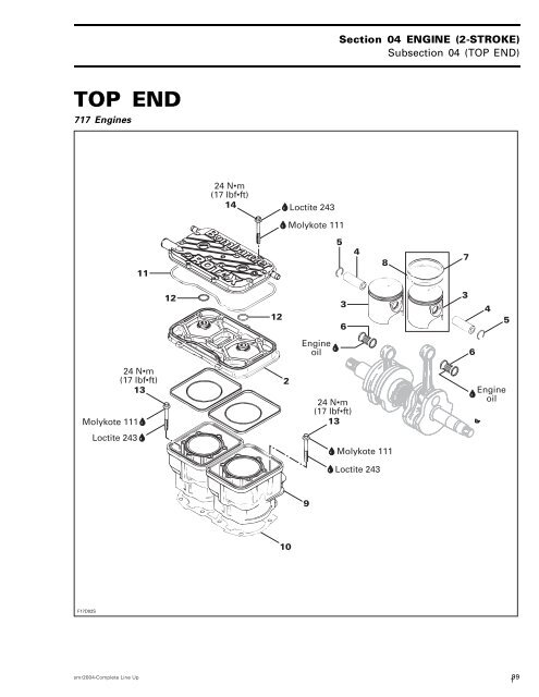
TOP END<br />
<strong>717</strong> <strong>Engines</strong><br />
Molykote 111<br />
F17D02S<br />
Loctite 243<br />
11<br />
24 N•m<br />
(17 lbf•ft)<br />
13<br />
12<br />
24 N•m<br />
(17 lbf•ft)<br />
14<br />
12<br />
2<br />
10<br />
Loctite 243<br />
Molykote 111<br />
Engine<br />
oil<br />
9<br />
Section 04 ENGINE (2-STROKE)<br />
Subsection 04 (TOP END)<br />
5<br />
3<br />
6<br />
24 N•m<br />
(17 lbf•ft)<br />
13<br />
4<br />
Molykote 111<br />
Loctite 243<br />
3<br />
6<br />
4<br />
Engine<br />
oil<br />
smr2004-Complete Line Up 99<br />
1<br />
8<br />
7<br />
5
Section 04 ENGINE (2-STROKE)<br />
Subsection 04 (TOP END)<br />
787 RFI <strong>Engines</strong><br />
F07D0US<br />
5<br />
4<br />
Molykote 111<br />
15<br />
30<br />
16 17 19<br />
29 27<br />
8<br />
26 25<br />
10 N•m<br />
(89 lbf•in)<br />
18<br />
7<br />
8<br />
3<br />
20 21<br />
3 N•m<br />
(27 lbf•in)<br />
24 23 22<br />
Molykote 111<br />
5<br />
(34 rollers)<br />
6<br />
Loctite<br />
243<br />
Molykote<br />
111<br />
Engine oil<br />
Molykote<br />
111<br />
12<br />
14 27 N•m<br />
(20 lbf•ft)<br />
12<br />
Loctite 243<br />
1<br />
11<br />
2<br />
Molykote<br />
111<br />
13<br />
40 N•m<br />
(30 lbf•ft)<br />
100 smr2004-Complete Line Up<br />
9<br />
10<br />
2
947 DI <strong>Engines</strong><br />
26<br />
10 N•m<br />
(89 lbf•in)<br />
F12D0TS<br />
15<br />
6<br />
7<br />
8<br />
18<br />
3 N•m<br />
(27 lbf•in)<br />
16 17 19 20<br />
Molykote 111<br />
25<br />
Loctite 243<br />
3<br />
24 23 22<br />
4<br />
5<br />
Engine oil<br />
Loctite<br />
243<br />
Engine oil<br />
Section 04 ENGINE (2-STROKE)<br />
Subsection 04 (TOP END)<br />
14 40 N•m<br />
(30 lbf•ft)<br />
Molykote 111<br />
13<br />
40 N•m<br />
(30 lbf•ft)<br />
2<br />
34<br />
Molykote<br />
111<br />
Loctite<br />
243<br />
smr2004-Complete Line Up 101<br />
3<br />
9<br />
10
Section 04 ENGINE (2-STROKE)<br />
Subsection 04 (TOP END)<br />
GENERAL<br />
The 2-stroke ROTAX engine rotates counterclockwise<br />
seen from the rear (PTO flywheel).<br />
The <strong>717</strong> and 787 RFI engines have a rotary valve<br />
to control opening and closing of the intake. The<br />
947 DI engines uses reed valves in the crankcase.<br />
The 787 RFI and 947 DI engines are also equipped<br />
with the RAVE system (Rotax Adjustable Variable<br />
Exhaust).<br />
CAUTION: No engine components can be interchanged<br />
between engines.<br />
RAVE System<br />
(Rotax Adjustable Variable Exhaust)<br />
BASIC OPERATION<br />
The RAVE valves change the height of the exhaust<br />
port. The RAVE valve solenoid, which is controlled<br />
by the MPEM, allows either positive crankcase<br />
pressure (787 RFI engines) or a pressure from the<br />
air compressor (947 DI engines) to inflate the bellowsandopentheRAVEvalves.<br />
On top of the RAVE, there is a red plastic adjustment<br />
knob. Turning the adjustment in or out<br />
changes the preload on the return spring which,<br />
in turn, will change the RPM at which the RAVE<br />
valve opens and closes. On 947 DI engines, the<br />
spring preload does not have a significant effect<br />
on the valve operation.<br />
787 RFI <strong>Engines</strong><br />
On these engines, the RAVE valves are controlled<br />
by the Multi-Purpose Electronic Module (MPEM).<br />
To open the RAVE valves, the MPEM activates a<br />
solenoid which directs the positive pressure from<br />
engine crankcase to the valves.<br />
F06D3BA<br />
1. Solenoid<br />
2. Pressure hose from crankcase<br />
3. To atmospheric pressure<br />
2<br />
1 3<br />
NOTE: A check valve on the pressure line eliminates<br />
the negative pressure from the crankcase.<br />
To close the RAVE valves, the MPEM deactivates<br />
the solenoid which blocks the crankcase positive<br />
pressure. The RAVE valves are opened to the atmosphere.<br />
3<br />
2<br />
1<br />
F06D16A<br />
RAVE VALVE OPENED<br />
1. Pulse from crankcase<br />
2. Check valve<br />
3. Positive pressure to solenoid<br />
4. Solenoid activated<br />
5. Positive crankcase pressure to RAVE valves<br />
102 smr2004-Complete Line Up<br />
5<br />
4<br />
4
2<br />
3<br />
1<br />
F06D16B<br />
RAVE VALVE CLOSED<br />
1. Pulse from crankcase<br />
2. Check valve<br />
3. Positive pressure blocked by the solenoid<br />
4. Solenoid deactivated<br />
5. RAVE valves are opened to atmosphere<br />
947 DI <strong>Engines</strong><br />
To open the RAVE valves, the MPEM activates a<br />
solenoid which directs the pressure from air compressor<br />
to the valves.<br />
F12D02A<br />
1. Pressure from solenoid<br />
4<br />
1<br />
5<br />
4<br />
F12D15A<br />
Section 04 ENGINE (2-STROKE)<br />
Subsection 04 (TOP END)<br />
5<br />
1. Solenoid<br />
2. Pressure from air compressor<br />
3. Pressure to RAVE valves<br />
4. Vent to air intake silencer<br />
5. Check valve<br />
6. Vent from counterbalancing shaft oil cavity<br />
1<br />
6<br />
2 3<br />
To close the RAVE valves, the MPEM deactivates<br />
the solenoid which blocks the air compressor<br />
pressure. The RAVE valves are opened to the<br />
atmosphere.<br />
The vent on couterbalancing shaft oil cavity is necessary<br />
to prevent pressure buildup in the cavity by<br />
the air compressor piston movement. The check<br />
valve allows pressure to escape from the cavity<br />
but does not allow liquid to enter into the cavity.<br />
smr2004-Complete Line Up 103<br />
5
Section 04 ENGINE (2-STROKE)<br />
Subsection 04 (TOP END)<br />
3<br />
1 F12D04A<br />
RAVE VALVE OPENED<br />
1. Pressure from air compressor<br />
2. Solenoid activated<br />
3. Pressure to solenoid<br />
4. Pressure to RAVE valves<br />
3<br />
1 F12D05A<br />
RAVE VALVE CLOSED<br />
1. Pressure from air compressor<br />
2. Solenoid deactivated<br />
3. Pressure to solenoid<br />
4. Pressure to RAVE valves blocked by the solenoid<br />
5. Vent to air intake silencer<br />
6. Check valve<br />
7. Counterbalancing shaft oil cavity vent<br />
4<br />
4<br />
6<br />
2<br />
2<br />
7<br />
5<br />
MAINTENANCE<br />
There are no wear parts anywhere in the system<br />
and there are no adjustments to be periodically<br />
checked. The only possible maintenance required<br />
would be cleaning of carbon deposits from<br />
the guillotine slide. Cleaning intervals would depend<br />
upon the user's riding style and the quality<br />
of the oil used. We suggest annual cleaning of<br />
the valve. If a customer uses a lower than recommended<br />
quality oil, more frequent cleaning may<br />
be required.<br />
No special solvents or cleaners are required when<br />
cleaning the valve.<br />
BORING PRECAUTION<br />
In its stock configuration the RAVE valve guillotine<br />
has a minimum of 0.5 mm (.020 in) clearance<br />
to the cylinder bore measured at the center line<br />
of the cylinder. This is the minimum production<br />
clearance.<br />
There is only a first oversize piston available for<br />
the 787 RFI and 947 DI engines. That piston is<br />
0.25 mm (.010 in) larger in diameter than the stock<br />
piston. When the oversize is installed, the guillotine<br />
will have a minimum clearance of 0.375 mm<br />
(.015 in) with the cylinder bore. This is the minimum<br />
operating clearance the guillotine should be<br />
used with. Clearance less than 0.375 mm (.015 in)<br />
will require reworking of the guillotine to achieve<br />
the proper clearance and radius.<br />
DISASSEMBLY<br />
RAVE Valve<br />
787 RFI <strong>Engines</strong><br />
Loosen Allen screws no. 26 each side of RAVE<br />
valve.<br />
104 smr2004-Complete Line Up<br />
6
F06D0QA 1<br />
1. Remove screws<br />
Remove RAVE valve no. 15.<br />
Remove the cover no. 18 of the valve by releasing<br />
the spring no. 16.<br />
WARNING<br />
Firmly hold cover to valve base. The compression<br />
spring inside the valve is applying<br />
pressure against the cover.<br />
F06D0RA 1<br />
1. Spring<br />
Remove the compression spring no. 19.<br />
F06D25A<br />
Section 04 ENGINE (2-STROKE)<br />
Subsection 04 (TOP END)<br />
1<br />
1. Remove spring<br />
787 RFI <strong>Engines</strong><br />
Remove spring no. 30 retaining bellows no. 21 to<br />
valve piston no. 20.<br />
F06D0SA 1<br />
1. Spring<br />
Free bellows no. 21 from valve piston no. 20.<br />
smr2004-Complete Line Up 105<br />
7
Section 04 ENGINE (2-STROKE)<br />
Subsection 04 (TOP END)<br />
F06D0TA 1<br />
1. Bellows removed from piston<br />
Unscrew valve piston no. 20 from sliding valve<br />
no. 22.<br />
NOTE: Hold the sliding valve to prevent it from<br />
turning.<br />
F06D0TB 1<br />
2<br />
1. Unscrew piston<br />
2. Hold sliding valve<br />
Remove compression spring no. 29.<br />
A06D26A<br />
1. Remove spring<br />
1<br />
Remove supporting ring no. 28.<br />
F06D27A<br />
1<br />
1. Remove supporting ring<br />
Remove O-ring no. 23.<br />
106 smr2004-Complete Line Up<br />
8
F06D28A<br />
1. Remove O-ring<br />
1<br />
Remove sliding valve no. 22.<br />
F06D0UA 1<br />
1. Remove sliding valve<br />
Remove bellows no. 21.<br />
F06D0VA<br />
Section 04 ENGINE (2-STROKE)<br />
Subsection 04 (TOP END)<br />
1<br />
1. Remove bellows<br />
947 DI <strong>Engines</strong><br />
Loosen Allen screws no. 26 each side of RAVE<br />
valve.<br />
F12D0UA 1<br />
1. Remove screws<br />
Remove RAVE valve no. 15.<br />
Remove the cover no. 18 of the valve by releasing<br />
the spring no. 16.<br />
WARNING<br />
Firmly hold cover to valve base. The compression<br />
spring inside the valve is applying<br />
pressure against the cover.<br />
smr2004-Complete Line Up 107<br />
9<br />
1
Section 04 ENGINE (2-STROKE)<br />
Subsection 04 (TOP END)<br />
F12D0VA<br />
1. Spring<br />
Remove the compression spring no. 19.<br />
F12D0WA<br />
1<br />
1. Remove spring<br />
Unscrew valve piston no. 20 from sliding valve<br />
no. 22.<br />
NOTE: Hold the sliding valve to prevent it from<br />
turning.<br />
1<br />
F12D0XA<br />
1<br />
1. Unscrew piston<br />
2. Hold sliding valve<br />
Remove sliding valve from valve housing.<br />
F12D0YA 1<br />
2 3<br />
1. Valve piston<br />
2. Valve housing<br />
3. Sliding valve<br />
Cylinder Head Cover and Cylinder Head<br />
Disconnect temperature sensor wire and spark<br />
plug cables.<br />
Connect spark plug cables on grounding device.<br />
<strong>717</strong> <strong>Engines</strong><br />
Remove air intake silencer and support, refer to<br />
AIR INTAKE.<br />
<strong>717</strong> and 787 RFI <strong>Engines</strong><br />
Remove screws no. 14.<br />
Remove cylinder head cover no. 1.<br />
If shells, sand, salt or any other particles are<br />
present in cylinder head, clean with a vacuum<br />
cleaner.<br />
108 smr2004-Complete Line Up<br />
2<br />
10
Remove cylinder head no. 2.<br />
If shells, sand, salt water or any other particles<br />
are present in cylinder cooling jacket, clean with<br />
a vacuum cleaner.<br />
947 DI <strong>Engines</strong><br />
Disconnect hose of RAVE valves. Remove air/fuel<br />
rail. Refer to ENGINE MANAGEMENT.<br />
Use Snap-On Torx socket E12 and unscrew cylinder<br />
head screws no. 14 following the sequence<br />
shown in the next illustration.<br />
2<br />
F12D08B<br />
6<br />
1<br />
9<br />
12<br />
7<br />
5<br />
11<br />
3<br />
10 8<br />
Remove cylinder head no. 2 and gasket no. 34.<br />
Cylinder<br />
NOTE: When removing cylinder, make sure connecting<br />
rods do not hit crankcase edge.<br />
787 RFI <strong>Engines</strong><br />
Remove air intake silencer and support, refer to<br />
AIR INTAKE.<br />
<strong>717</strong> and 787 RFI <strong>Engines</strong><br />
Remove tuned pipe and exhaust manifold, refer to<br />
EXHAUST SYSTEM.<br />
Remove screws no. 13.<br />
Remove cylinders no. 9, while making sure connecting<br />
rods do not hit crankcase edge.<br />
WARNING<br />
If screws need to be heated for removal when<br />
engine is in watercraft, fuel system pressurization<br />
must be done first. Do not use open<br />
flame; use a heat gun.<br />
NOTE: Even if only 1 cylinder needs repair, both<br />
cylinders should be lifted to allow 1-piece cylinder<br />
base gasket replacement.<br />
4<br />
Section 04 ENGINE (2-STROKE)<br />
Subsection 04 (TOP END)<br />
947 DI <strong>Engines</strong><br />
Remove cylinders screws then cylinders no. 9.<br />
Piston<br />
NOTE: All engines feature cageless piston pin<br />
bearings.<br />
<strong>717</strong> and 787 RFI <strong>Engines</strong><br />
Bring piston to Top Dead Center and install rubber<br />
pad (P/N 295 000 101) over crankcase opening.<br />
Secure with screws. Lower piston until it sits on<br />
pad.<br />
F01B0JA<br />
1. Rubber pad (P/N 295 000 101)<br />
1<br />
If the other cylinder has been removed, completely<br />
cover its opening with a clean rag.<br />
F01D43A<br />
1. Openings covered with rag and rubber pad<br />
947 DI <strong>Engines</strong><br />
Install rubber pad (P/N 290 877 032) on crankcase.<br />
Secure with screws. Lower piston to be removed<br />
until it sits on pad.<br />
smr2004-Complete Line Up 109<br />
11<br />
1
Section 04 ENGINE (2-STROKE)<br />
Subsection 04 (TOP END)<br />
F06B06B 1<br />
1. Rubber pad (P/N 290 877 032)<br />
All <strong>Engines</strong><br />
To remove circlip no. 5, insert a pointed tool in<br />
piston notch then pry it out and discard.<br />
WARNING<br />
Always wear safety glasses when removing<br />
piston circlips.<br />
F01D0PA<br />
TYPICAL<br />
1. Piston notch<br />
To extract piston pin no. 4, use piston pin puller<br />
(P/N 529 035 503) with the appropriate set of<br />
sleeves.<br />
ENGINE SLEEVE SET P/N<br />
<strong>717</strong>/787 RFI 529 035 542<br />
947 DI 529 035 543<br />
1<br />
F00B0IA<br />
1. Puller<br />
2. Shoulder sleeve<br />
3. Sleeve<br />
1<br />
2 3<br />
– Fully thread on puller handle.<br />
– Insert extractor spindle into the piston pin.<br />
– Slide the sleeve and shoulder sleeve onto the<br />
spindle.<br />
– Screw in extracting nut with the movable extracting<br />
ring toward spindle.<br />
F00B0JA<br />
1. Puller<br />
2. Sleeve<br />
3. Shoulder sleeve<br />
4. Extracting nut<br />
1 2 3 4<br />
NOTE: The tool cutout must be positioned toward<br />
the bottom of the piston.<br />
110 smr2004-Complete Line Up<br />
12
F00B0KA 1<br />
1. Tool cut-out toward bottom of piston<br />
– Firmly hold puller and rotate handle to pull piston<br />
pin no. 4.<br />
– Rotate spindle until the shoulder sleeve is<br />
flushed with the piston recess.<br />
F00B0LA<br />
1. Shoulder sleeve flush with piston recess<br />
– Loosen the extracting nut and remove puller.<br />
– Remove the shoulder sleeve from piston.<br />
1<br />
F00B0MA<br />
Section 04 ENGINE (2-STROKE)<br />
Subsection 04 (TOP END)<br />
1. Remove shoulder sleeve<br />
– Carefully remove the piston no. 3.<br />
– The needles, thrust washers and the sleeve remain<br />
in the connecting rod bore and may be<br />
used again.<br />
F00B0NA<br />
1. Needles and thrust washer<br />
2. Sleeve<br />
CLEANING<br />
1 2<br />
Discard all gaskets and O-rings.<br />
Clean all metal components in a solvent.<br />
Clean water passages and make sure they are not<br />
clogged.<br />
Remove carbon deposits from cylinder exhaust<br />
port, RAVE valve (787 RFI and 947 DI engines),<br />
cylinder head and piston dome.<br />
Clean piston ring grooves with a groove cleaner<br />
tool, or a piece of broken ring.<br />
smr2004-Complete Line Up 111<br />
13<br />
1
Section 04 ENGINE (2-STROKE)<br />
Subsection 04 (TOP END)<br />
INSPECTION<br />
Visually inspect all parts for corrosion damage.<br />
Inspect piston for damage. Light scratches can be<br />
sanded with a fine sand paper.<br />
NOTE: When repairing a seized engine, connecting<br />
rods should be checked for straightness and<br />
crankshaft for deflection/misalignment. Refer to<br />
BOTTOM END for procedures.<br />
Inspect plane surfaces for warpage. Small deformation<br />
can be corrected by grinding surface with<br />
a fine sand paper. Install sand paper on a surface<br />
plate and rub part against oiled sand paper.<br />
The inspection of engine top end should include<br />
the following measurements.<br />
ENGINE<br />
MEASUREMENT<br />
Cylinder taper N.A.<br />
Cylinder out of round N.A.<br />
Piston/cylinder<br />
wall clearance<br />
<strong>717</strong> engine<br />
Piston/cylinder<br />
wall clearance<br />
787 RFI engine<br />
Piston/cylinder<br />
wall clearance<br />
947 DI engine<br />
Ring/piston<br />
groove clearance<br />
<strong>717</strong> engine<br />
Ring/piston<br />
groove clearance<br />
787 RFI engine<br />
Ring/piston<br />
groove clearance<br />
947 DI engine<br />
Ring end gap<br />
<strong>717</strong> engine<br />
Ring end gap<br />
787 RFI engine<br />
Ring end gap<br />
947 DI engine<br />
N.A.: NOT APPLICABLE<br />
TOLERANCES<br />
NEW PARTS<br />
(min.) (max.)<br />
0.10 mm<br />
(.0039 in)<br />
0.13 mm<br />
(.005 in)<br />
0.12 mm<br />
(.0047 in)<br />
0.025 mm<br />
(.001 in)<br />
0.025 mm<br />
(.001 in)<br />
0.044 mm<br />
(.002 in)<br />
0.25 mm<br />
(.010 in)<br />
0.40 mm<br />
(.016 in)<br />
0.55 mm<br />
(.022 in)<br />
0.05 mm<br />
(.002 in)<br />
0.008 mm<br />
(.0003 in)<br />
N.A.<br />
N.A<br />
N.A.<br />
0.070 mm<br />
(.0027 in)<br />
0.070 mm<br />
(.0027 in)<br />
0.089 mm<br />
(.003 in)<br />
0.40 mm<br />
(.016 in)<br />
0.55 mm<br />
(.022 in)<br />
0.7 mm<br />
(.028 in)<br />
WEAR<br />
LIMIT<br />
0.1 mm<br />
(.004 in)<br />
0.08 mm<br />
(.003 in)<br />
0.20 mm<br />
(.008 in)<br />
0.24 mm<br />
(.009 in)<br />
0.20 mm<br />
(.008 in)<br />
0.20 mm<br />
(.008 in)<br />
0.24 mm<br />
(.009 in)<br />
0.20 mm<br />
(.008 in)<br />
1.0 mm<br />
(.039 in)<br />
1.0 mm<br />
(.039 in)<br />
1.1 mm<br />
(.043 in)<br />
NOTE: Replacement cylinder sleeves are available<br />
if necessary. Also, oversize pistons of 0.25 mm<br />
(.010 in) are available for all engines and oversize<br />
pistons of 0.5 mm (.020 in) are available for the<br />
<strong>717</strong> engine.<br />
Cylinder Taper<br />
Using a cylinder bore gauge, measure cylinder diameter<br />
at 16 mm (5/8 in) from top of cylinder just<br />
below auxiliary transfer port, facing exhaust port<br />
and just below the auxiliary transfer port facing<br />
the exhaust port. Compare readings. If the difference<br />
between readings exceed specification,<br />
cylinder should be rebored and honed or replaced.<br />
112 smr2004-Complete Line Up<br />
14
A<br />
F01D8AA<br />
2<br />
1. Measuring perpendicularly (90°) topistonpinaxis<br />
2. Auxiliary transfer port<br />
A. 16 mm (5/8 in)<br />
1<br />
Cylinder Out of Round<br />
Using a cylinder bore gauge, measure cylinder<br />
diameter at 16 mm (5/8 in) from top of cylinder.<br />
Measure diameter in piston pin axis direction<br />
then perpendicularly (90°) to it. If the difference<br />
between readings exceed specification, cylinder<br />
should be rebored and honed or replaced.<br />
F01D8BA<br />
Section 04 ENGINE (2-STROKE)<br />
Subsection 04 (TOP END)<br />
A<br />
1. Measuringinpistonpinaxis<br />
2. Measuring perpendicularly (90°) to piston pin axis<br />
A. 16 mm (5/8 in)<br />
1<br />
USED PISTON MEASUREMENT<br />
Note the measurement on the piston dome.<br />
F00D0EA 2 1<br />
1. Piston dome<br />
2. Piston measurement<br />
Using a micrometer, measure piston skirt perpendicularly<br />
(90°) to piston pin according to the following<br />
table.<br />
ENGINE TYPE MAXIMUM “A” mm (in)<br />
<strong>717</strong> 29 (1.142)<br />
smr2004-Complete Line Up 113<br />
15<br />
A<br />
2
Section 04 ENGINE (2-STROKE)<br />
Subsection 04 (TOP END)<br />
F01D0NA<br />
787 RFI 28 (1.102)<br />
947 DI 24 (0.945)<br />
1. Measuring perpendicularly (90°) topistonpinaxis<br />
A. See previous table<br />
ENGINE TYPE<br />
A<br />
1<br />
MAXIMUM PISTON<br />
SKIRT WEAR mm (in)<br />
All 0.12 (.005)<br />
The measured dimension must not be less than<br />
0.12 mm (.005 in) of the one scribed on piston<br />
dome. Otherwise, install a new piston.<br />
Piston/Cylinder Wall Clearance<br />
Used and New Pistons<br />
IMPORTANT: Make sure used piston is not worn<br />
more than specified. See USED PISTON MEA-<br />
SUREMENT above.<br />
To determine the piston dimension, take the measurement<br />
on the piston dome.<br />
F00D0EA 2 1<br />
1. Piston dome<br />
2. Piston measurement<br />
Adjust and lock a micrometer to the specified value<br />
on the piston dome.<br />
F00B08A<br />
1. Micrometer set to the piston dimension<br />
With the micrometer set to the piston dimension,<br />
adjust a cylinder bore gauge to the micrometer<br />
dimension and set the indicator to zero.<br />
114 smr2004-Complete Line Up<br />
1<br />
16
F00B09A<br />
2<br />
1. Use the micrometer to set the cylinder bore gauge<br />
2. Dial bore gauge<br />
F00B0AA<br />
1. Indicator set to zero<br />
Position the dial bore gauge at 16 mm (5/8 in) below<br />
cylinder top edge.<br />
1<br />
1<br />
F01D0KA<br />
Section 04 ENGINE (2-STROKE)<br />
Subsection 04 (TOP END)<br />
A<br />
1. Measuring perpendicularly (90°) to piston pin axis<br />
A. 16 mm (5/8 in)<br />
Read the measurement on the cylinder bore<br />
gauge. The result is the exact piston/cylinder wall<br />
clearance.<br />
NOTE: Make sure the cylinder bore gauge indicator<br />
is set exactly at the same position as with the<br />
micrometer, otherwise the reading will be false.<br />
Ring/Piston Groove Clearance<br />
<strong>717</strong> and 787 RFI <strong>Engines</strong><br />
Using a feeler gauge, check clearance between<br />
rectangular ring and groove. If clearance exceeds<br />
specified tolerance, replace piston.<br />
NOTE: Ring/piston groove clearance can be correctly<br />
measured only on rectangular ring which is<br />
bottom ring.<br />
F01D0XA<br />
1. Feeler gauge<br />
2. Rectangular ring (bottom)<br />
smr2004-Complete Line Up 115<br />
17<br />
1<br />
1<br />
2
Section 04 ENGINE (2-STROKE)<br />
Subsection 04 (TOP END)<br />
947 DI <strong>Engines</strong><br />
Due to the semi-trapez rings, it is not possible to<br />
accurately measure ring/piston groove clearance.<br />
Ring End Gap<br />
Position ring halfway between exhaust port and<br />
top of cylinder.<br />
NOTE: In order to correctly position ring in cylinder,<br />
use piston as a pusher.<br />
Using a feeler gauge, check ring end gap. If gap<br />
exceeds specified tolerance, rings should be replaced.<br />
F01D0OA 1<br />
1. Top of cylinder<br />
2. Ring end gap<br />
Cylinder Base Gasket<br />
NOTE: The general procedure is to install a new<br />
gasket of the same thickness. However, if you<br />
do not know the gasket thickness that was installed<br />
or if a crank repair has involved replacement<br />
of connecting rods, refer to the COMBUS-<br />
TION CHAMBER VOLUME MEASUREMENT to<br />
properly determine the required gasket thickness.<br />
Different thicknesses of cylinder base gaskets are<br />
used for a precise adjustment of the combustion<br />
chamber volume.<br />
To identify gasket thickness, refer to the identification<br />
holes on the gasket.<br />
2<br />
F01D67A<br />
TYPICAL<br />
1. Identification holes<br />
All <strong>Engines</strong><br />
GASKET THICKNESS<br />
1<br />
IDENTIFICATION<br />
HOLES<br />
0.3 mm (.012 in) 3<br />
0.4 mm (.016 in) 4<br />
0.5 mm (.020 in) 5<br />
0.6 mm (.024 in) 6<br />
0.8 mm (.031 in) 8<br />
RAVE Valve<br />
787 RFI and 947 DI <strong>Engines</strong><br />
Check RAVE valve bellows no. 21 for cracks.<br />
ASSEMBLY<br />
Assembly is essentially the reverse of disassembly<br />
procedures. However pay particular attention<br />
to the following.<br />
RAVE Valve<br />
787 RFI <strong>Engines</strong><br />
Make sure to insert O-ring no. 23 onto rod of sliding<br />
valve no. 22.<br />
The TOP position of the sliding valve no. 22 is<br />
indicated on one side.<br />
116 smr2004-Complete Line Up<br />
18
F01D8KA 1 3 2<br />
1. Sliding valve<br />
2. O-ring<br />
3. TOP<br />
Install a new gasket no. 24. It must be installed<br />
at the same time as the sliding valve no. 22.<br />
Position the valve housing no. 25 onto the cylinder<br />
so that its opening is toward the bottom.<br />
F01D8JB 1<br />
1. Bottom of valve housing<br />
When the valve is mounted onto the cylinder,<br />
move the valve piston no. 20 to ensure the sliding<br />
valve no. 22 moves easily and does not stick.<br />
F01D8LA<br />
Section 04 ENGINE (2-STROKE)<br />
Subsection 04 (TOP END)<br />
947 DI <strong>Engines</strong><br />
Check the piston valve O-ring. Replace if necessary.<br />
F12D0ZA<br />
1. Piston valve O-ring<br />
Check the sliding valve O-ring. Replace if necessary.<br />
smr2004-Complete Line Up 117<br />
19<br />
1
Section 04 ENGINE (2-STROKE)<br />
Subsection 04 (TOP END)<br />
F12D10A<br />
1<br />
1. Sliding valve O-ring<br />
Check the O-ring under valve housing. Replace if<br />
necessary.<br />
F12D11A<br />
1<br />
1. Valve housing O-ring<br />
All RAVE-Equipped <strong>Engines</strong><br />
There is only one way to insert the sliding valve<br />
no. 22 in valve housing no. 25.<br />
F06D12A<br />
1. Sliding valve ridge toward housing groove<br />
Piston<br />
At assembly, place the pistons no. 3 with the letters<br />
“AUS” (over an arrow on the piston dome)<br />
facing in direction of the exhaust port.<br />
A01C01A<br />
1<br />
1. Exhaust side<br />
AUS<br />
NOTE: On the 787 RFI and 947 DI engines, the<br />
exhaust ports are located on the same side as the<br />
intake.<br />
Carefully cover crankcase opening as for disassembly.<br />
Piston Pin and Roller Bearing<br />
To install roller bearing no. 4 and piston pin no. 6<br />
use, piston pin puller (P/N 529 035 503) with the<br />
appropriate set of sleeves as for disassembly.<br />
– Replacement bearings are held in place by a locating<br />
sleeve outside and 2 plastic cage halves<br />
inside.<br />
– Push needle bearing together with inner halves<br />
out of the locating sleeve into the connecting<br />
rod bore.<br />
118 smr2004-Complete Line Up<br />
1<br />
20
– Replace the inner halves by the appropriate<br />
sleeve tool in the connecting rod bore.<br />
– Insert piston pin into piston until it comes flush<br />
with inward edge of piston hub.<br />
– Warm piston to approximately 50 - 60°C (122-<br />
140°F) and install it over connecting rod.<br />
NOTE: Make sure thrust washers are present<br />
each side of needles.<br />
– Install the shoulder sleeve tool on the opposite<br />
side of the piston pin.<br />
F00B0OA<br />
1<br />
1. Piston pin<br />
2. Shoulder sleeve<br />
– Insert extractor spindle into the piston pin,<br />
screw on extracting nut.<br />
F00B0PA<br />
2<br />
1. Puller installed on the opposite side of the piston pin<br />
2. Tighten extracting nut<br />
– Rotate handle to pull piston pin carefully into the<br />
piston.<br />
1<br />
2<br />
Section 04 ENGINE (2-STROKE)<br />
Subsection 04 (TOP END)<br />
Plastic Mounting Device Method<br />
This is an alternate method when no service tool<br />
is available.<br />
Replacement roller bearings are delivered in a convenient<br />
plastic mounting device. For installation,<br />
proceed as follows:<br />
– Align replacement roller bearing with connecting<br />
rod bore.<br />
– Carefully push inner plastic sleeve into connecting<br />
rod bore; outer plastic ring will release<br />
rollers.<br />
F01D0QA<br />
1. Outer ring removal after inner sleeve insertion into bore<br />
– Make sure thrust washers are present each<br />
side of rollers.<br />
F01D0VA<br />
1<br />
1. Thrust washer each side<br />
– Insert piston pin into piston until it comes flush<br />
with inward edge of piston hub.<br />
smr2004-Complete Line Up 119<br />
21<br />
1
Section 04 ENGINE (2-STROKE)<br />
Subsection 04 (TOP END)<br />
F01D0RA<br />
1<br />
1. Piston pin flush here<br />
2. Thrust washers<br />
– Place piston over connecting rod and align<br />
bores, then gently tap piston pin with a fiber<br />
hammer to push out inner plastic ring on opposite<br />
side. Support piston from opposite side.<br />
F01D0SA<br />
– As necessary, pull halves of inner sleeve with<br />
long nose pliers.<br />
2<br />
F01D0TA<br />
1. Pulling inner sleeve half<br />
1<br />
Circlip<br />
Always use new circlips.<br />
WARNING<br />
Always wear safety glasses when installing<br />
piston circlips.<br />
CAUTION: Always use new circlips. At installation,<br />
take care not to deform them. Circlips<br />
must not move freely after installation.<br />
<strong>717</strong> and 787 RFI <strong>Engines</strong><br />
Secure circlip with its opening located at the bottom<br />
of the piston.<br />
CAUTION: To minimize the stress on the<br />
circlips, it is important to install them as described.<br />
F06D18A<br />
1. Circlip opening at 6 o'clock (at bottom)<br />
120 smr2004-Complete Line Up<br />
1<br />
22
947 DI <strong>Engines</strong><br />
Securecirclipinpistongroovewithitsbentendin<br />
piston notch as shown.<br />
F07D0AB<br />
1. Circlip end in piston notch<br />
All <strong>Engines</strong><br />
To easily insert circlip into piston, use circlip installer.<br />
ENGINE TOOL P/N<br />
<strong>717</strong> and 787 RFI 529 035 562<br />
947 DI 529 035 563<br />
F06B01A 1<br />
TYPICAL<br />
1. Circlip installer<br />
– Remove sleeve from pusher then insert circlip<br />
into its bore.<br />
– Reinstall sleeve onto pusher and push until circlip<br />
comes in end of tool.<br />
1<br />
F00B0QA<br />
Section 04 ENGINE (2-STROKE)<br />
Subsection 04 (TOP END)<br />
TYPICAL<br />
1. Circlip near end of tool<br />
– Position end of tool against piston pin opening.<br />
– Firmly hold piston against tool and tap tool with<br />
a hammer to insert circlip into its groove.<br />
F00B0RA<br />
CAUTION: The hand retaining the piston<br />
should absorb the energy to protect the connecting<br />
rod.<br />
Cylinder Base Gasket<br />
Install new base gasket.<br />
NOTE: The general procedure is to install a new<br />
gasket of the same thickness. However, if you<br />
do not know the gasket thickness that was installed<br />
or if a crankshaft and/or crankcase repair<br />
or replacement was involved, refer to the COM-<br />
BUSTION CHAMBER VOLUME MEASUREMENT<br />
to properly determine the required gasket thickness.<br />
Five thicknesses of cylinder base gaskets are available<br />
for a precise adjustment of the squish gap.<br />
To identify gasket thickness, refer to the identification<br />
holes on the gasket.<br />
smr2004-Complete Line Up 121<br />
23<br />
1
Section 04 ENGINE (2-STROKE)<br />
Subsection 04 (TOP END)<br />
Cylinder<br />
<strong>717</strong> and 787 RFI <strong>Engines</strong><br />
To easily slide cylinder no. 9 over piston, use piston<br />
ring compressor (P/N 290 876 979).<br />
A01B1TA<br />
1. Slide this edge<br />
NOTE: Ring compressor will not fit on oversize<br />
parts.<br />
Makesuretoalignringendgapwithpistonlocating<br />
pin. Slide tool over rings.<br />
F01D0ZA<br />
1. Ringendgapalignedwithpistonlocatingpin<br />
Slide cylinder over piston.<br />
1<br />
1<br />
F01D10A<br />
When reassembling cylinders to crankcase, it is<br />
important to have them properly aligned so that<br />
exhaust flanges properly match up with exhaust<br />
manifold.<br />
<strong>717</strong> <strong>Engines</strong><br />
The aligning tool (P/N 420 876 904) or the exhaust<br />
manifold can be used to align cylinders.<br />
F01D44A 1<br />
<strong>717</strong> ENGINES<br />
1. Exhaust flange aligning tool<br />
122 smr2004-Complete Line Up<br />
24
F01D45A<br />
<strong>717</strong> ENGINES<br />
1. Aligning cylinders using exhaust manifold<br />
787 RFI <strong>Engines</strong><br />
The exhaust manifold is used to align cylinders.<br />
F00D0FA 1<br />
787 RFI ENGINES<br />
1. Aligning cylinders using exhaust manifold<br />
Cylinder Block<br />
947 DI <strong>Engines</strong><br />
Install cylinder base gasket no. 10. There is only<br />
one way to install gasket.<br />
The cylinder block is positioned with locating dowels.<br />
Line up dowels with corresponding holes in cylinder<br />
block.<br />
1<br />
F02D0UA 1<br />
1. Dowels<br />
Section 04 ENGINE (2-STROKE)<br />
Subsection 04 (TOP END)<br />
To easily slide cylinder block over pistons, use ring<br />
compressor (P/N 290 876 965).<br />
A01B1TA<br />
1. Slide this edge<br />
NOTE: For each ring, make sure to align ring end<br />
gapwithpistonlocatingpin.<br />
Install cylinder block.<br />
Apply Molykote 111 on O-ring no. 31 and install it.<br />
CAUTION: The O-rings must be installed and<br />
properly positioned in the cylinder block. The<br />
O-rings are meant to dampen stud vibration.<br />
Cylinder Screw<br />
<strong>717</strong> <strong>Engines</strong><br />
Apply Molykote 111 below the screw head.<br />
Apply also Loctite 243 (blue) on screw threads.<br />
Install and torque screws no. 13 in a criss-cross<br />
sequence for each cylinder to 24 N m(17lbfft). Refer to the following illustration.<br />
smr2004-Complete Line Up 123<br />
25<br />
1<br />
1
Section 04 ENGINE (2-STROKE)<br />
Subsection 04 (TOP END)<br />
F01D35A<br />
1 4 1 4<br />
3 2 3 2<br />
787 RFI <strong>Engines</strong><br />
Prior installation, apply Molykote 111 below screw<br />
head and Loctite 243 (blue) on screw threads.<br />
Install M10 x 105 screws on exhaust side and the<br />
M10 x 73.5 on opposite side.<br />
Torque screws in a criss-cross sequence for each<br />
cylinderto20N m(15lbfft). Repeat the procedure,<br />
retightening all cylinder screws to 40 N m<br />
(30 lbf ft).<br />
F01D7FA<br />
2<br />
3 3 2<br />
4 1 1 4<br />
947 DI <strong>Engines</strong><br />
Apply Molykote 111 below the screw head.<br />
The blue coating underneath the cylinder screw<br />
head can be only used once. Either replace with<br />
new bolts or remove blue coating and apply<br />
Molykote 111 below the screw heads.<br />
Install and torque screws to 40 N m(30lbf ft) in<br />
the indicated order. Refer to the following illustration.<br />
F12D07A<br />
7 2 3 5<br />
6<br />
All <strong>Engines</strong><br />
4<br />
Cylinder Head<br />
Install cylinder head gasket.<br />
<strong>717</strong> and 787 RFI <strong>Engines</strong><br />
Make sure to install O-rings no. 12 around spark<br />
plug holes and O-ring no. 11 of cylinder head as<br />
shown in the following illustration.<br />
F01D5AA 1<br />
1. O-rings<br />
1<br />
Apply Loctite 518 in O-ring groove of cylinder<br />
sleeves.<br />
947 DI <strong>Engines</strong><br />
Apply Loctite 243 (blue) below head of cylinder<br />
head bolts no. 14.<br />
124 smr2004-Complete Line Up<br />
1<br />
8<br />
26
Apply Molykote 111 on threads of cylinder head<br />
bolts no. 14.<br />
Torque bolts to 20 N m(15lbfft) as per following<br />
sequence in the next illustration. Repeat the<br />
torquing sequence by retightening to 40 N m<br />
(30 lbf ft).<br />
11<br />
F12D08A<br />
7<br />
12<br />
2<br />
4<br />
1<br />
Cylinder Head Cover<br />
<strong>717</strong> and 787 RFI <strong>Engines</strong><br />
Install cylinder head cover no. 1.<br />
Apply Loctite 243 (blue) below head of screws<br />
no. 14.<br />
Apply also Molykote 111 on threads of screws<br />
no. 14.<br />
Torque cylinder head screws no. 14 to 12 N m<br />
(106 lbf in) as per following illustrated sequence.<br />
Repeat the procedure, retightening all screws to<br />
24 N m(17lbfft). F01D46A<br />
8<br />
6<br />
3<br />
10<br />
10 8 2 4 6 12<br />
9 7<br />
TORQUING SEQUENCE<br />
3 1 5<br />
11<br />
5<br />
9<br />
Section 04 ENGINE (2-STROKE)<br />
Subsection 04 (TOP END)<br />
ADJUSTMENT<br />
RAVE Valve<br />
787 RFI <strong>Engines</strong><br />
Turn the red plastic knob no. 17 until it is flush to<br />
the valve cover.<br />
F00D0GA<br />
1. Knob flush with the cover<br />
Combustion Chamber Volume<br />
Measurement<br />
All <strong>Engines</strong><br />
NOTE: This procedure is required to determine<br />
the thickness of the cylinder base gasket to be installed<br />
if a crank repair has involved replacement<br />
of connecting rods or if you are experiencing<br />
repetitive engine seizure.<br />
The combustion chamber volume is the region in<br />
the cylinder head above the piston at Top Dead<br />
Center. It is measured with the cylinder head installedontheengine.<br />
F01D5VA<br />
1. Combustion chamber<br />
NOTE: When checking the combustion chamber<br />
volume, engine must be cold, piston must be free<br />
of carbon deposit and cylinder head must be leveled.<br />
smr2004-Complete Line Up 125<br />
27<br />
1<br />
1
Section 04 ENGINE (2-STROKE)<br />
Subsection 04 (TOP END)<br />
All <strong>Engines</strong> except 947 DI<br />
– Remove both spark plugs and bring one piston<br />
to Top Dead Center a using a TDC gauge.<br />
F01D2IA<br />
1. Bring piston to TDC<br />
947 DI <strong>Engines</strong><br />
– Remove both direct injectors and bring one piston<br />
to Top Dead Center using a TDC gauge.<br />
Keep spark plugs in their holes.<br />
All <strong>Engines</strong><br />
– Obtain a graduated burette (capacity 0 - 50 cc)<br />
and fill with an equal part (50/50) of gasoline and<br />
injection oil.<br />
1<br />
F00B0BA<br />
1<br />
1. Graduated burette (0 - 50 cc)<br />
– Open burette valve to fill its tip. Add liquid in<br />
burette until level reaches 0 cc.<br />
– Inject the burette content through the spark<br />
plug hole on all engines except 947 DI and<br />
through direct injector hole on DI engines until<br />
liquid touches the top hole.<br />
F00D0HA 1<br />
1. Top of spark plug hole<br />
NOTE: The liquid level in cylinder must not drop<br />
for a few seconds after filling. If so, there is a<br />
leak between piston and cylinder. The recorded<br />
volume would be false.<br />
– Let burette stand upward for about 10 minutes,<br />
until liquid level is stabilized.<br />
– Read the burette scale to obtain the quantity of<br />
liquid injected in the combustion chamber.<br />
126 smr2004-Complete Line Up<br />
28
Compare the obtained value with the table below.<br />
Thevolumeshouldbewithintheallowablerange.<br />
If the volume of the combustion chamber is not<br />
within specifications, change cylinder base gasket<br />
thickness as follow.<br />
A higher volume dictates a thinner gasket.<br />
A lower volume dictates a thicker gasket.<br />
All <strong>Engines</strong> except DI<br />
NOTE: When the combustion chamber is filled to<br />
top of spark plug hole, it includes an amount of<br />
2.39 cc corresponding to the spark plug tip. The<br />
following table of combustion chamber volume includes<br />
this value.<br />
All <strong>Engines</strong><br />
ENGINE<br />
COMBUSTION CHAMBER<br />
VOLUME<br />
<strong>717</strong> 31.2 - 34.0 cc<br />
787 RFI 34.7 - 37.9 cc<br />
947 DI 45.7 - 48.4 cc<br />
– Repeat the procedure for the other cylinder(s).<br />
Section 04 ENGINE (2-STROKE)<br />
Subsection 04 (TOP END)<br />
smr2004-Complete Line Up 127<br />
29
BOTTOM END<br />
<strong>717</strong> <strong>Engines</strong><br />
F00D0YU<br />
110 N•m<br />
(81 lbf•ft)<br />
1<br />
5<br />
24 N•m<br />
9<br />
(17 lbf•ft)<br />
6<br />
Molykote<br />
111<br />
Molykote<br />
111<br />
4<br />
6<br />
11<br />
2<br />
7<br />
24 N•m<br />
(17 lbf•ft)<br />
Anti-seize<br />
lubricant<br />
4<br />
Anti-seize<br />
lubricant<br />
Loctite<br />
518<br />
10<br />
10 N•m<br />
(89 lbf•in)<br />
12<br />
3<br />
Loctite<br />
5910<br />
8<br />
40 N•m<br />
(30 lbf•ft)<br />
Loctite<br />
518<br />
Molykote<br />
111<br />
Section 04 ENGINE (2-STROKE)<br />
Subsection 05 (BOTTOM END)<br />
Loctite<br />
642<br />
Loctite<br />
243<br />
6<br />
Loctite<br />
518<br />
2<br />
12<br />
11<br />
4 Anti-seize<br />
lubricant<br />
6 4<br />
Molykote<br />
111<br />
smr2004-Complete Line Up 129<br />
30<br />
5
Section 04 ENGINE (2-STROKE)<br />
Subsection 05 (BOTTOM END)<br />
787 RFI <strong>Engines</strong><br />
Anti-seize<br />
lubricant<br />
F07D0VS<br />
110 N•m<br />
(81 lbf•ft)<br />
1<br />
Molykote<br />
111<br />
Anti-seize<br />
lubricant<br />
Molykote<br />
111<br />
Loctite<br />
5910<br />
5<br />
Loctite<br />
518<br />
Molykote<br />
111<br />
40 N•m<br />
(30 lbf•ft)<br />
8<br />
9 N•m<br />
(80 lbf•in)<br />
4<br />
6<br />
15<br />
18<br />
Anti-seize<br />
lubricant<br />
11<br />
14<br />
Anti-seize<br />
lubricant<br />
19<br />
4<br />
6<br />
12<br />
30 mL (1 oz)<br />
SAE 30<br />
motor oil<br />
Molykote<br />
111<br />
3<br />
2<br />
2<br />
13<br />
Loctite<br />
642<br />
Loctite<br />
243<br />
Molykote<br />
111<br />
Loctite<br />
518<br />
Loctite<br />
518<br />
Molykote 111<br />
Loctite<br />
518<br />
24 N•m<br />
7<br />
(17 lbf•ft)<br />
7<br />
24 N•m<br />
Molykote 111<br />
(17 lbf•ft) 8<br />
40 N•m<br />
(30 lbf•ft)<br />
Anti-seize lubricant<br />
16<br />
12<br />
11<br />
Anti-seize<br />
lubricant<br />
4<br />
15<br />
6<br />
4<br />
Anti-seize<br />
lubricant<br />
130 smr2004-Complete Line Up<br />
6<br />
31
947 DI <strong>Engines</strong><br />
28<br />
5<br />
F18D2QS<br />
30 9 N•m<br />
(80 lbf•in)<br />
Molykote 111<br />
7 N•m<br />
(62 lbf•in)<br />
24<br />
25<br />
4<br />
Loctite 243<br />
9<br />
27<br />
Loctite 243<br />
Loctite<br />
518<br />
Molykote<br />
111<br />
1.5 N•m<br />
(13 lbf•in)<br />
Loctite 243<br />
6<br />
29<br />
Loctite<br />
243<br />
Anti-seize<br />
lubricant<br />
23<br />
Molykote<br />
111<br />
27 N•m<br />
(20 lbf•ft)<br />
Anti-seize<br />
lubricant<br />
7<br />
3<br />
6.5 N•m<br />
(58 lbf•in)<br />
Molykote<br />
111<br />
14<br />
16<br />
15<br />
17<br />
Anti-seize<br />
lubricant<br />
Loctite 243<br />
13<br />
6<br />
Molykote<br />
111<br />
6<br />
7<br />
4<br />
2<br />
Loctite<br />
5910<br />
4<br />
20 N•m<br />
(15 lbf•ft)<br />
8<br />
5<br />
Section 04 ENGINE (2-STROKE)<br />
Subsection 05 (BOTTOM END)<br />
8<br />
40 N•m<br />
(30 lbf•ft)<br />
Loctite<br />
243<br />
2<br />
7<br />
27 N•m<br />
(20 lbf•ft)<br />
Molykote<br />
31 111<br />
32<br />
15<br />
13<br />
1<br />
115 N•m<br />
(85 lbf•ft)<br />
22 23 N•m<br />
6.5 N•m<br />
(17 lbf•ft)<br />
(58 lbf•in)<br />
20<br />
XP DI<br />
only<br />
21<br />
Synthetic<br />
grease<br />
Engine<br />
oil<br />
Loctite 648<br />
21<br />
23 N•m<br />
(17 lbf•ft)<br />
smr2004-Complete Line Up 131<br />
32
Section 04 ENGINE (2-STROKE)<br />
Subsection 05 (BOTTOM END)<br />
DISASSEMBLY<br />
Engine has to be removed from watercraft and top<br />
end has to be disassembled to open bottom end.<br />
Refer to REMOVAL AND INSTALLATION and TOP<br />
END.<br />
PTO Flywheel<br />
<strong>717</strong> <strong>Engines</strong><br />
To remove PTO flywheel no. 1, the crankshaft<br />
must be locked. Refer to MAGNETO SYSTEM<br />
and follow the procedure to lock the magneto flywheel.<br />
PTO flywheel is loosen using PTO flywheel remover<br />
(P/N 295 000 001).<br />
F01J0TA<br />
Insert special tool in PTO flywheel splines.<br />
F01D1AA<br />
TYPICAL<br />
1. PTO flywheel remover (P/N 295 000 001)<br />
Using a suitable wrench or socket with a breaker<br />
bar, unscrew PTO flywheel COUNTERCLOCK-<br />
WISE when facing it and hold extension handle<br />
locking the magneto flywheel.<br />
1<br />
F00D0ZA<br />
TYPICAL<br />
1. Extension handle locking crankshaft<br />
1<br />
NOTE: When splines of PTO flywheel are worn<br />
out and special tool cannot be used, proceed with<br />
the following alternate method.<br />
Use a pipe wrench and install it on PTO flywheel<br />
as illustrated.<br />
F00D10A<br />
TYPICAL<br />
1. Extension handle locking crankshaft<br />
1<br />
787 RFI <strong>Engines</strong><br />
PTO flywheel is loosened using PTO flywheel extractor<br />
(P/N 295 000 156).<br />
132 smr2004-Complete Line Up<br />
F00B04A<br />
33
Install special tool.<br />
F06I02A<br />
1<br />
1. PTO flywheel extractor<br />
Install the extension handle (P/N 295 000 125) on<br />
the PTO flywheel extractor. Loosen PTO flywheel<br />
COUNTERCLOCKWISE when facing it.<br />
947 DI <strong>Engines</strong> except XP DI<br />
Use PTO flywheel remover (P/N 295 000 001) to<br />
hold flywheel and remove Allen screws no. 21 retaining<br />
coupler no. 20 to PTO flywheel.<br />
F01J0TA<br />
PTO FLYWHEEL REMOVER TOOL<br />
Section 04 ENGINE (2-STROKE)<br />
Subsection 05 (BOTTOM END)<br />
F06D37A 2 1<br />
1. Loosen Allen screws<br />
2. Breaker bar locking crankshaft<br />
Remove the coupler no. 20.<br />
XP DI Models<br />
Remove Allen screws no. 21.<br />
F08D02A<br />
1. PTO flywheel<br />
2. Coupler<br />
3. Loosen Allen screw<br />
2<br />
Remove coupler no. 20.<br />
947 DI <strong>Engines</strong><br />
Install puller plate (P/N 529 035 533) and extension<br />
handle (P/N 295 000 125) to PTO flywheel.<br />
NOTE: Puller plate can be used without the extension<br />
handle.<br />
smr2004-Complete Line Up 133<br />
34<br />
1<br />
3
Section 04 ENGINE (2-STROKE)<br />
Subsection 05 (BOTTOM END)<br />
Loosen bolt no. 22 retaining the PTO flywheel to<br />
the crankshaft using a suitable socket and breaker<br />
bar.<br />
F06D38A<br />
2<br />
1. Puller plate<br />
2. Extension handle<br />
3. Loosen bolt with socket and breaker bar<br />
3<br />
Remove the PTO flywheel using puller plate<br />
(P/N 529 035 533) and puller (P/N 529 035 547)<br />
and bolt (P/N 529 035 549).<br />
F06D39A<br />
1. Puller plate<br />
2. Puller<br />
3. Bolt<br />
4. Extension handle<br />
4 3 1<br />
Starter Drive Assembly<br />
947 DI <strong>Engines</strong> Only<br />
Loosen 2 Allen screws no. 24 retaining starter<br />
drive cover no. 25.<br />
1<br />
2<br />
F06D1CA<br />
1. Cover<br />
2. Allen screw<br />
2<br />
Remove starter drive cover no. 25 and spring<br />
no. 9.<br />
Remove starter drive assembly no. 27.<br />
F06D1DA 1<br />
TYPICAL — 947 DI ENGINES<br />
1. Starter drive assembly<br />
Reed Valve<br />
947 DI <strong>Engines</strong> Only<br />
Remove reed valves no. 28 from crankcase.<br />
Crankcase<br />
Before opening the bottom end, remove the following<br />
parts:<br />
– engine supports (<strong>717</strong> engines)<br />
134 smr2004-Complete Line Up<br />
1<br />
35
– magneto flywheel, refer to MAGNETO SYS-<br />
TEM<br />
– magneto housing (except 947 DI engines)<br />
– starter<br />
– rotary valve cover and valve (except 947 DI engines)<br />
– starter drive assembly (947 DI engines)<br />
– reed valves (947 DI engines)<br />
– air compressor cover (947 DI engines).<br />
<strong>717</strong> and 787 RFI <strong>Engines</strong><br />
Put engine on a stand. Loosen crankcase screws.<br />
1<br />
F01D20C<br />
<strong>717</strong> ENGINES<br />
1. M10 x 73.5 flanged screws<br />
2. M8 x 68.5 flanged screws<br />
3. M8 x 45 socket head screws<br />
2<br />
1 1 1<br />
F15D05A 2<br />
787 RFI ENGINES<br />
1. M10 x 73.5 flanged screws<br />
2. M8 x 53.5 flanged screws<br />
2<br />
3<br />
3<br />
Section 04 ENGINE (2-STROKE)<br />
Subsection 05 (BOTTOM END)<br />
947 DI <strong>Engines</strong><br />
Place engine upright on crankcase magneto side.<br />
Loosen crankcase screws.<br />
1<br />
F07D09D<br />
947 DI ENGINES<br />
1. M8 x 45 flanged screws<br />
2. M10 x 73.5 flanged screws<br />
2<br />
All <strong>Engines</strong><br />
Put engine back on a support. Insert a pry bar<br />
between crankcase lugs to separate halves.<br />
CAUTION: Be careful to precision machined<br />
surfaces.<br />
F01D1KA<br />
TYPICAL<br />
1. Separate halves by prying at provided lugs<br />
smr2004-Complete Line Up 135<br />
1<br />
1
Section 04 ENGINE (2-STROKE)<br />
Subsection 05 (BOTTOM END)<br />
F01D1LA<br />
1<br />
TYPICAL<br />
1. Separate halves by prying at provided lugs<br />
Remove crankshaft and counterbalance shaft (787<br />
RFIand947DIengines).<br />
947 DI <strong>Engines</strong><br />
Open air compressor and disconnect the piston as<br />
described in ENGINE MANAGEMENT.<br />
Crankshaft Bearing and Seal<br />
All <strong>Engines</strong><br />
If a crankshaft end seal no. 5 hastobereplaced,<br />
bottom end must be opened (except for the MAG<br />
side seal on the 787 RFI engines, which is mounted<br />
on the magneto housing).<br />
NOTE: Do not needlessly remove crankshaft bearings.<br />
Remove end seal(s).<br />
F06D1GA 1<br />
TYPICAL<br />
1. End seal<br />
<strong>717</strong> <strong>Engines</strong><br />
To remove end bearings no. 4 from crankshaft,<br />
use the following tools.<br />
F01B09A<br />
1 2 3 4 5 6<br />
7<br />
8<br />
<strong>717</strong> ENGINES<br />
1. Puller (P/N 420 877 635)<br />
2. Protective cap (P/N 420 876 557)<br />
3. Distance ring, MAG side only (P/N 420 876 569)<br />
4. Ring (both sides) (P/N 420 977 490)<br />
5. MAG side ring halves (P/N 420 276 025)<br />
6. PTO side ring halves (P/N 420 977 475)<br />
7. Screw M8 x 40 (P/N 420 840 681)<br />
8. Screw M8 x 70 (P/N 420 841 201)<br />
NOTE: To facilitate ring or distance ring installation,<br />
lubricate their inside diameters.<br />
787 RFI <strong>Engines</strong><br />
To remove end bearings no. 4 from crankshaft,<br />
use the following tools.<br />
NOTE: The outer PTO bearing and crankshaft gear<br />
can be removed in one step using another puller.<br />
See CRANKSHAFT GEAR no. 18.<br />
F01B2MA<br />
1 2 3 4 5<br />
787 RFI ENGINES<br />
1. Puller (P/N 420 877 635)<br />
2. Protective cap (P/N 420 876 557)<br />
3. Distance ring (P/N 420 876 569)<br />
4. Ring (P/N 420 977 490)<br />
5. Ring halves (P/N 420 977 475)<br />
6. Screw M8 x 40 (P/N 420 840 681)<br />
7. Screw M8 x 70 (P/N 420 841 201)<br />
6<br />
7<br />
NOTE: To facilitate ring or distance ring installation,<br />
lubricate their inside diameters.<br />
947 DI <strong>Engines</strong><br />
To remove end bearings from crankshaft, use the<br />
following tools.<br />
136 smr2004-Complete Line Up
F06B03A<br />
6<br />
6<br />
947 DI ENGINES<br />
1. Puller (P/N 420 877 635)<br />
2. Protective cap (P/N 290 877 414)<br />
3. Distance ring (P/N 420 876 56)<br />
4. Ring (P/N 420 977 480)<br />
5. Ring halves (P/N 420 876 330)<br />
6. Screw (P/N 420 841 201)<br />
All <strong>Engines</strong><br />
F01D1OA<br />
TYPICAL<br />
1. Removing crankshaft bearing<br />
1<br />
2<br />
1<br />
Or, use a bearing extractor such as Proto no. 4332<br />
and a press to remove two bearings at a time (except<br />
on PTO side for the 787 RFI engines).<br />
3<br />
4<br />
5<br />
F01D1PA<br />
Section 04 ENGINE (2-STROKE)<br />
Subsection 05 (BOTTOM END)<br />
1<br />
1. Press bearings out<br />
2. Bearing extractor<br />
Crankshaft Gear<br />
787 RFI <strong>Engines</strong><br />
The crankshaft gear no. 18 and bearing no. 5 can<br />
be removed in one step using the following puller.<br />
F04B03A<br />
1<br />
1. Puller (P/N 290 877 665)<br />
smr2004-Complete Line Up 137<br />
2
Section 04 ENGINE (2-STROKE)<br />
Subsection 05 (BOTTOM END)<br />
Install the puller as per following illustration.<br />
F00D0IA 2 1<br />
1. Puller<br />
2. Protective cap<br />
Secure puller in a vise and remove gear and bearing.<br />
F00D0JA<br />
NOTE: If the inner PTO bearing needs to be replaced,<br />
remove the Woodruff key on the crankshaft.<br />
Counterbalance Shaft<br />
787 RFI <strong>Engines</strong><br />
Bearings no. 15 on counterbalance shaft no. 13<br />
can be removed by using the following tools:<br />
F00B0CA<br />
5<br />
1. Puller (P/N 420 877 635)<br />
2. Protective cap (P/N 420 876 557)<br />
3. Ring (P/N 420 977 480)<br />
4. Ring halves (P/N 420 876 330)<br />
5. Screw M8 x 40 (P/N 420 840 681)<br />
F00D0KA 1<br />
1. Tool installed<br />
1 2 3 4<br />
To remove gear no. 14, first trace an index mark<br />
on the gear and counterbalance shaft.<br />
NOTE: There is no Woodruff key to position the<br />
gear on the counterbalance shaft. An index mark<br />
must be traced to ease assembly procedure.<br />
F00D0SA<br />
1. Index mark<br />
1<br />
Use a press to remove the gear no. 14 from the<br />
counterbalance shaft.<br />
138 smr2004-Complete Line Up
F00D0TA<br />
947 DI <strong>Engines</strong><br />
Use a press to remove counterweights no. 16 and<br />
bearings no. 15.<br />
CAUTION: There is no woodruff key to position<br />
the counterweights. An index mark must be<br />
traced to retain the proper position of the counterweight.<br />
F06D1HA<br />
1. Trace an index mark<br />
Remove seals no. 17.<br />
Remove bearing no. 31 and washer no. 32.<br />
Use a press to remove gear no. 14.<br />
CLEANING<br />
1<br />
All Models<br />
Discard all oil seals, gaskets, O-rings and sealing<br />
rings.<br />
Clean oil passages and make sure they are not<br />
clogged.<br />
Section 04 ENGINE (2-STROKE)<br />
Subsection 05 (BOTTOM END)<br />
Clean all metal components in a solvent.<br />
Crankcase mating surfaces are best cleaned using<br />
a combination of the chisel gasket remover<br />
(P/N 413 708 500) and a brass brush. Brush a first<br />
pass in one direction then make the final brushing<br />
perpendicularly (90°) to the first pass cross (hatch).<br />
CAUTION: Do not wipe with rags. Use a new<br />
clean hand towel only.<br />
F00D2BA<br />
F00D2CA<br />
FIRST PASS<br />
smr2004-Complete Line Up 139
Section 04 ENGINE (2-STROKE)<br />
Subsection 05 (BOTTOM END)<br />
F00D2DA<br />
SECOND PASS<br />
Finish the cleaning with acetone.<br />
CAUTION: Ensure to clean compressor lubrication<br />
nipple.<br />
CAUTION: Be careful not to spray cleaner on<br />
the painted surface of the engine.<br />
CAUTION: Never use a sharp object to scrape<br />
away old sealant as score marks incurred are<br />
detrimental to crankcase sealing.<br />
INSPECTION<br />
Assembled Engine<br />
The following checks can be performed with engine<br />
in watercraft without overhauling engine.<br />
Crankshaft Alignment at Center<br />
Main Journal<br />
Since it is an assembled crankshaft it can become<br />
misaligned or deflected. Crankshaft can be twisted<br />
on center main journal, changing timing of one<br />
cylinder in relation with the other.<br />
F01D1NA<br />
1. Main journal alignment here<br />
1<br />
To accurately check if crankshaft is twisted on center<br />
main journal, proceed as follows:<br />
– Remove magneto housing cover.<br />
– Remove flywheel nut (and magneto rotor for<br />
the 787 RFI and 947 DI engines). Refer to<br />
MAGNETO SYSTEM for procedures.<br />
– Install Bombardier degree wheel (P/N 529 035<br />
607)) on crankshaft end. Hand-tighten nut only.<br />
– Remove both spark plugs.<br />
– Install a TDC gauge in spark plug hole on MAG<br />
side.<br />
– Bring MAG piston at Top Dead Center.<br />
– As a needle pointer, secure a wire with a cover<br />
screw and a washer.<br />
– Rotate degree wheel (NOT crankshaft) so that<br />
needle pointer reads 360°.<br />
140 smr2004-Complete Line Up
F01D4IA<br />
1<br />
3<br />
TYPICAL<br />
1. TDC gauge<br />
2. Degree wheel<br />
3. Hand tighten nut<br />
4. Needle pointer<br />
– Remove TDC gauge and install on PTO side.<br />
– Bring PTO piston at Top Dead Center.<br />
Interval between cylinders must be exactly 180°<br />
therefore, needle pointer must indicate 180° on<br />
degree wheel (360° -180°= 180°).<br />
Any other reading indicates a misaligned crankshaft.<br />
CrankshaftAlignmentatConnecting<br />
Rod Journal<br />
Counterweights can also be twisted on connecting<br />
rod journal on any or both cylinder(s).<br />
2<br />
4<br />
F01D1NB<br />
Section 04 ENGINE (2-STROKE)<br />
Subsection 05 (BOTTOM END)<br />
1. Connecting rod journal alignment here<br />
1<br />
Such misalignment may make it difficult to manually<br />
turn the crankshaft. Verification can be done<br />
by measuring deflection each end of crankshaft.<br />
If deflection is found greater than specified tolerance,<br />
this indicates worn bearing(s), bent and/or<br />
disaligned crankshaft. Proceed with the disassembly<br />
of the engine.<br />
Disassembled Engine<br />
The following verifications can be performed with<br />
theenginedisassembled.<br />
Crankcase<br />
Inspect plane surfaces for warpage. Small deformation<br />
can be corrected by grinding surface with<br />
a fine sandpaper. Install sandpaper on a surface<br />
plate and rub part against oiled sand paper.<br />
Bearing<br />
Inspect crankshaft bearings no. 4. Check for corrosion,<br />
scoring, pitting, chipping or other evidence<br />
of wear. Make sure plastic cage is not melted.<br />
Rotate and make sure they turn smoothly.<br />
Crankshaft<br />
NOTE: If crankshaft and/or components are<br />
found defective, it must be repaired by a specialized<br />
shop or replaced.<br />
Connecting Rod Straightness<br />
Align a steel ruler on edge of small end connecting<br />
rod bore. Check if ruler is perfectly aligned with<br />
edge of big end.<br />
smr2004-Complete Line Up 141
Section 04 ENGINE (2-STROKE)<br />
Subsection 05 (BOTTOM END)<br />
F01D1QA<br />
1. Ruler must be aligned with edge of connecting rod here<br />
2. Align ruler here<br />
Crankshaft Deflection<br />
All Models<br />
MEASUREMENT MAG SIDE PTO SIDE<br />
Crankshaft<br />
deflection (max.)<br />
2<br />
0.050 mm<br />
(.002 in)<br />
1<br />
0.030 mm<br />
(.001 in)<br />
Crankshaft deflection is measured each end with<br />
a dial indicator.<br />
First, check deflection with crankshaft in<br />
crankcase. If deflection exceeds the specified<br />
tolerance, it can be either ball bearings wear, bent<br />
or twisted crankshaft at connecting rod journal.<br />
F01D1SA<br />
1. Measuring PTO side deflection in crankcase<br />
1<br />
F01D1TA<br />
1<br />
1. Measuring MAG side deflection in crankcase<br />
Remove crankshaft bearings and check deflection<br />
again on V-shaped blocks as illustrated.<br />
F01D97A<br />
1<br />
1. Measuring MAG side deflection on V-shaped blocks<br />
F01D98A<br />
1. Measuring PTO side deflection on V-shaped blocks<br />
142 smr2004-Complete Line Up<br />
1
NOTE: Crankshaft deflection cannot be correctly<br />
measured between centers of a lathe.<br />
Connecting Rod Big End Axial Play<br />
CONNECTING ROD BIG END AXIAL PLAY<br />
MODEL<br />
<strong>717</strong><br />
engines<br />
787 RFI<br />
engines<br />
947 DI<br />
engines<br />
NEW PARTS<br />
(min.) (max.)<br />
0.311 mm<br />
(.012 in)<br />
0.230 mm<br />
(.008 in)<br />
0.390 mm<br />
(.015 in)<br />
0.677 mm<br />
(.026 in)<br />
0.617 mm<br />
(.024 in)<br />
0.737 mm<br />
(.029 in)<br />
WEAR<br />
LIMIT<br />
1.2 mm<br />
(.047 in)<br />
1.2 mm<br />
(.047 in)<br />
1.2 mm<br />
(.047 in)<br />
Using a feeler gauge, measure distance between<br />
thrust washer and crankshaft counterweight.<br />
F01D1WA<br />
1<br />
2<br />
1. Measuring big end axial play<br />
2. Feeler gauge<br />
Starter Drive Bearing<br />
947 DI <strong>Engines</strong> Only<br />
Check bearing no. 23 of starter drive assembly<br />
no. 27 in crankcase.<br />
F06D1IA<br />
Section 04 ENGINE (2-STROKE)<br />
Subsection 05 (BOTTOM END)<br />
1. Bearing of starter drive assembly<br />
1<br />
Removal<br />
Starter drive bearing can be easily removed from<br />
lower crankcase half using the following suggested<br />
tool or equivalent:<br />
– Snap-onhammerpullerincluding:<br />
– handle CJ93-1<br />
– hammer CJ125-6<br />
– claws CJ93-4.<br />
F01J0ZA<br />
Closepullerclawssothattheycanbeinsertedin<br />
end bearing. Holding claws, turn puller shaft clock<br />
wise so that claws open and become firmly tight<br />
against bearing.<br />
Slide puller hammer outwards and tap puller end.<br />
Retighten claws as necessary to always maintain<br />
them tight against bearing. Continue this way until<br />
bearing completely comes out.<br />
For installation, see below in this section.<br />
Reed Valve<br />
947 DI <strong>Engines</strong> Only<br />
Check reed valve petals no. 29 for cracks or other<br />
defects. The reed petals must lie completely flat<br />
against the reed valve body no. 30. To check, hold<br />
against light.<br />
smr2004-Complete Line Up 143
Section 04 ENGINE (2-STROKE)<br />
Subsection 05 (BOTTOM END)<br />
F06D1JA<br />
1. No play<br />
1<br />
In case of a play, turn reed petals upside down and<br />
recheck. If there is still a play, replace petals.<br />
Check perfect condition of rubber coating on reed<br />
valve body.<br />
Check stopper distance from center of reed valve<br />
block.<br />
F06D1EA<br />
A<br />
A. 13 ± 0.25 mm (.512 ± .010 in)<br />
NOTE: Distance should be the same on both<br />
sides.<br />
Bent stopper as required to obtain the proper distance.<br />
Air Compressor<br />
Refer to ENGINE MANAGEMENT for components<br />
inspection. However, if you find aluminum dust<br />
or debris in this area, they may have flowed toward<br />
the injection oil reservoir. In this case, the<br />
oil reservoir and lines must be flushed and the filter<br />
replaced.<br />
CAUTION: Failure to properly clean the oil system<br />
will result in serious engine damage.<br />
ASSEMBLY<br />
Assembly is essentially the reverse of disassembly<br />
procedures. However pay particular attention<br />
to the following.<br />
NOTE: It is recommended to spray<br />
BOMBARDIER-ROTAX injection oil on all<br />
moving parts when reassembling the engine.<br />
Crankshaft and Bearing<br />
Apply Loctite 767 anti-seize on part of crankshaft<br />
where bearing fits.<br />
Prior to installation, place bearings no. 4 into a<br />
container filled with oil, previously heated to 75°C<br />
(167°F). This will expand bearing and ease installation.<br />
To properly position the outer bearing(s), a distance<br />
gauge must be temporarily installed against<br />
the inner bearing. Slide the outer bearing until<br />
stopped by the distance gauge, then remove it.<br />
ENGINE DISTANCE GAUGE<br />
<strong>717</strong> (P/N 529 034 800) (PTO)<br />
787 RFI (P/N 529 034 900) (MAG)<br />
F01B0HA<br />
947DI<br />
1<br />
1. Distance gauge<br />
(P/N 529 035 100) (MAG)<br />
(P/N 529 035 000) (PTO)<br />
144 smr2004-Complete Line Up
F01D1YA<br />
TYPICAL<br />
1. Distance gauge<br />
2. Outer bearing<br />
1<br />
Distance Ring<br />
When installing the distance ring no. 12, make<br />
sure to position it with its chamfer toward the<br />
counterweight of the crankshaft.<br />
Crankshaft Gear<br />
787 RFI <strong>Engines</strong><br />
Position the long flange of the gear no. 18 toward<br />
the counterweight of the crankshaft. Also, make<br />
sure to align the gear keyway with the Woodruff<br />
key on the crankshaft.<br />
F00D0LA 1<br />
1. Woodruff key on the crankshaft<br />
2<br />
2<br />
F00D0MA<br />
Section 04 ENGINE (2-STROKE)<br />
Subsection 05 (BOTTOM END)<br />
1. Keyway<br />
2. Long flange toward the crankshaft counterweight<br />
Crankshaft Seal<br />
All Models<br />
When installing seal assembly no. 5, apply a light<br />
coat of lithium grease on seal lips.<br />
787 RFI <strong>Engines</strong><br />
Position PTO seal against the retaining shim; the<br />
gap between the seal no. 5 and bearing no. 4 will<br />
ensure proper lubrication of the bearing.<br />
F00D0NA<br />
1<br />
1. Seal against the retaining shim<br />
smr2004-Complete Line Up 145<br />
1
Section 04 ENGINE (2-STROKE)<br />
Subsection 05 (BOTTOM END)<br />
947 DI <strong>Engines</strong><br />
Seals are positioned with the outer lip in the<br />
crankcase recess.<br />
F06D1LA<br />
1. Seallipincrankcaserecess<br />
Drive Pin<br />
Make sure drive pins no. 6 of bearings are properly<br />
installed in crankcase recesses at assembly.<br />
F00D0OA<br />
1. Drive pins<br />
1<br />
Counterbalance Shaft<br />
787 RFI <strong>Engines</strong><br />
Press gear no. 14 onto counterbalance shaft<br />
no. 13 taking care to align both marks previously<br />
traced.<br />
CAUTION: Counterbalance shaft must be properly<br />
assembled, otherwise engine will vibrate<br />
and premature wear will occur.<br />
1<br />
Proceed as follows to check if the gear no. 14 is<br />
properly positioned on the counterbalance shaft:<br />
– Temporarily install the counterbalance shaft in<br />
the crankcase.<br />
– Rotate the counterbalance shaft to align the<br />
notch of the gear with the crankcase.<br />
F00D0UA<br />
1. Gear notch aligned with the crankcase<br />
– The notch of the couterweight on the opposite<br />
end of the counterbalance shaft must also be<br />
aligned with the cranckcase.<br />
F00D0VA<br />
1. Counterweight notch aligned with the crankcase<br />
If notches are not aligned with the crankcase, remove<br />
the gear and repeat the procedure until the<br />
notches are properly aligned.<br />
947 DI <strong>Engines</strong><br />
Install bearing no. 31 and washer no. 32.<br />
146 smr2004-Complete Line Up<br />
1<br />
1
When installing seals no. 17, apply a light coat of<br />
Molykote 111 on seal lips.<br />
Prior to installation, place bearings no. 15 into a<br />
container filled with oil, previously heated to 75°C<br />
(167°F). This will expand bearings and ease their<br />
installation.<br />
Reinstall counterweights no. 16 using a press and<br />
take care to align index marks previously traced.<br />
Crankshaft and Counterbalance Shaft<br />
787 RFI and 947 DI <strong>Engines</strong><br />
Install crankshaft no. 3 first in crankcase.<br />
After crankshaft installation, install counterbalance<br />
shaft no. 13. Make sure to properly index<br />
crankshaft and counterbalance shaft by gear aligning<br />
marks.<br />
CAUTION: Marks on the crankshaft and counterbalance<br />
shaft must be aligned, otherwise engine<br />
will vibrate and premature wear will occur.<br />
F00D0PA 1<br />
787 RFI ENGINES<br />
1. Marks must be aligned<br />
F06D1MA<br />
Section 04 ENGINE (2-STROKE)<br />
Subsection 05 (BOTTOM END)<br />
947 DI ENGINES<br />
1. Marks must be aligned<br />
1<br />
Turn by hand the crankshaft and counterbalance<br />
shaft. Make sure they do not interfere with the<br />
crankcase.<br />
947 DI <strong>Engines</strong><br />
Properly position bearing no. 31 and washer<br />
no. 32. Ensuretopositionlubricationholeontop<br />
(if so equipped).<br />
F12R16A 3 2 1<br />
1. Bearing<br />
2. Washer in crankcase groove<br />
3. Lubrication hole on top (if so equipped)<br />
Place seals no. 17 in their respective positions.<br />
smr2004-Complete Line Up 147
Section 04 ENGINE (2-STROKE)<br />
Subsection 05 (BOTTOM END)<br />
F06D1OA<br />
1. Seal in place<br />
1<br />
Air Compressor<br />
947 DI <strong>Engines</strong><br />
Refer to ENGINE MANAGEMENT for procedures.<br />
Crankcase<br />
All <strong>Engines</strong><br />
Crankcase halves are factory matched and therefore,<br />
are not interchangeable or available as single<br />
halves.<br />
<strong>717</strong> and 787 RFI <strong>Engines</strong><br />
Rotary valve shaft must be installed in crankcase<br />
before closing halves.<br />
CAUTION: Before joining crankcase halves,<br />
make sure that crankshaft gear is well engaged<br />
with rotary valve shaft gear.<br />
<strong>717</strong> <strong>Engines</strong><br />
Temporarily install armature plate to align<br />
crankcase halves with each other.<br />
CAUTION: Using different types of oil may reduce<br />
engine component life.<br />
All Models<br />
IMPORTANT: When beginning the application of<br />
the crankcase sealant, the assembly and the first<br />
torquing should be done within 10 minutes. It is<br />
suggested to have all you need on hand to save<br />
time.<br />
NOTE: It is recommended to apply this specific<br />
sealant as described here to get an uniform application<br />
without lumps. If you do not use the roller<br />
method, you may use your finger to uniformly distribute<br />
the sealant (unlike the Drei Bond sealing<br />
compound, using a finger will not affect the adhesion).<br />
Use the silicone-based Loctite 5910 (P/N 293 800<br />
081) on mating surfaces.<br />
NOTE: The sealant curing time is similar to the<br />
Loctite 518 without using the Primer N.<br />
CAUTION: Do not use Loctite 515 or 518 to seal<br />
crankcase. Do not use Loctite Primer N with<br />
the Loctite 5910. Using these products or non<br />
silicone-based sealant over a previously sealed<br />
crankcase with Loctite 5910 will lead to poor<br />
adhesion and possibly a leaking crankcase.<br />
These products are chemically incompatibles.<br />
Even after cleaning, the Loctite 5910 would<br />
leave incompatible microscopic particles.<br />
Use a plexiglass plate and apply some sealant on<br />
it. Use a soft rubber roller (50 - 75 mm (2 - 3 in))<br />
(available in arts products suppliers for printmaking)<br />
and roll the sealant to get a thin uniform coat<br />
on the plate (spread as necessary). When ready,<br />
apply the sealant on crankcase mating surfaces.<br />
148 smr2004-Complete Line Up<br />
F12R17A
F12R18A<br />
Do not apply in excess as it will spread out inside<br />
crankcase.<br />
CAUTION: If sealant spreads out inside air compressor<br />
area, it could plug the compressor lubrication<br />
nipple and serious compressor damage<br />
may occur.<br />
NOTE: Do not use Loctite Primer N with this<br />
sealant. The sealant curing time is similar to the<br />
Loctite 518 without using the Primer N, which is<br />
4to24hours.<br />
947 DI <strong>Engines</strong><br />
Make sure all locating dowels are in place.<br />
F06D1PA 1<br />
1. Dowel<br />
Counterbalance Shaft Bearing Cover<br />
787 RFI <strong>Engines</strong><br />
Install the bearing cover no. 19 with its hollow side<br />
toward the bearing.<br />
F00D0QA<br />
Section 04 ENGINE (2-STROKE)<br />
Subsection 05 (BOTTOM END)<br />
1. Hollow side facing bearing<br />
Crankcase Screws<br />
<strong>717</strong> <strong>Engines</strong><br />
Apply Loctite 518 on screw threads and Molykote<br />
111 below head screws.<br />
Torque crankcase screws to 24 N m(17lbfft) as<br />
per following illustrated sequence.<br />
F01D20D<br />
7 11 1 3 9 5 13<br />
8<br />
12<br />
4<br />
Torque 2 M10 crankcase screws to 40 N m<br />
(30 lbf ft).<br />
1<br />
F01D20B<br />
1. Torque to 40 N m(30lbfft)<br />
smr2004-Complete Line Up 149<br />
2<br />
10<br />
6<br />
1<br />
14
Section 04 ENGINE (2-STROKE)<br />
Subsection 05 (BOTTOM END)<br />
787 RFI <strong>Engines</strong><br />
Apply Loctite 518 on screw threads and Molykote<br />
111 below head screws.<br />
Torque crankcase screws to 12 N m(106lbfin) as per following sequence. Repeat procedure,<br />
retightening all screws to 24 N m(17lbfft). F15D05B<br />
11<br />
7 21 1 3 22 5 9<br />
19 12 17 8 13 15 4 2 16 14 18 6 20 10<br />
As a final step, torque only M10 screws no. 8 of<br />
crankcase to 40 N m(30lbf ft) as per following<br />
sequence.<br />
F15D05C<br />
11 7 1 3 5 9<br />
12 8 4 2 6 10<br />
947 DI <strong>Engines</strong><br />
Apply Molykote 111 below head of screws and<br />
Loctite 518 on threads.<br />
Torque crankcase screws to 12 N m(106lbfin) as per following sequence. Repeat procedure,<br />
retightening all screws to 27 N m(20lbfft). 9<br />
7<br />
14<br />
3<br />
1<br />
16<br />
5<br />
19<br />
11<br />
22<br />
F07D09E<br />
10<br />
24<br />
8<br />
21<br />
20<br />
4<br />
15<br />
13<br />
2<br />
17<br />
18<br />
6<br />
As a final step, torque only the M10 x 73.5 bolts<br />
to 40 N m(30lbf ft) as per following sequence.<br />
9<br />
7<br />
3<br />
1<br />
5<br />
11<br />
F07D09C<br />
Oil Fittings<br />
<strong>717</strong> and 787 RFI <strong>Engines</strong><br />
If inlet and outlet oil fittings no. 11 of rotary valve<br />
shaft have been removed from crankcase, reinstall<br />
them with their end pointing toward ignition housing.<br />
Apply Loctite 518 on threads of fittings.<br />
150 smr2004-Complete Line Up<br />
23<br />
12<br />
10<br />
8<br />
4<br />
2<br />
6<br />
12
Stud<br />
<strong>717</strong> <strong>Engines</strong><br />
At assembly in crankcase, apply Loctite 518<br />
on threads of studs no. 10. Torqueto10Nm<br />
(89 lbf in).<br />
Starter Drive Bearing<br />
947 DI <strong>Engines</strong><br />
To install bearing no. 23 of starter drive assembly,<br />
use pusher (P/N 420 876 502) and handle (P/N 420<br />
877 650).<br />
1<br />
2<br />
F06D32A<br />
1. Handle<br />
2. Pusher<br />
PTO Flywheel<br />
787 RFI <strong>Engines</strong><br />
Install O-ring onto crankshaft.<br />
F01D84A<br />
1. O-ring<br />
1<br />
Section 04 ENGINE (2-STROKE)<br />
Subsection 05 (BOTTOM END)<br />
<strong>717</strong> and 787 <strong>Engines</strong><br />
Apply Loctite anti-seize lubricant (P/N 293 800<br />
070) to crankshaft threads.<br />
Using the same tools as for disassembly procedure,<br />
torque PTO flywheel to 110 N m(81lbfft). 947 DI <strong>Engines</strong><br />
Apply Loctite 243 (blue) on bolt no. 22.<br />
Using the same tools as for disassembly procedure,<br />
torque bolt no. 22 to 115 N m(85lbfft). ApplyLoctite648onmatingsurfaceofPTOflywheel<br />
and coupler.<br />
Apply Loctite 243 (blue) to Allen screws no. 21 of<br />
coupler and torque to 23 N m(17lbfft). Final Assembly<br />
<strong>717</strong> and 787 RFI <strong>Engines</strong><br />
For rotary valve timing and assembly procedures,<br />
refer to ROTARY VALVE.<br />
787 RFI <strong>Engines</strong><br />
When engine assembly is completed, add 30 mL<br />
(1 oz) of motor oil SAE 30 to the counterbalance<br />
shaft gear through the crankcase filler plug.<br />
F07D06A<br />
1. Remove plug and add SAE 30 motor oil<br />
smr2004-Complete Line Up 151<br />
1
Section 04 ENGINE (2-STROKE)<br />
Subsection 05 (BOTTOM END)<br />
947 DI <strong>Engines</strong><br />
Add 40 mL (1.35 oz) of Sea-Doo synthetic jet pump<br />
oil (P/N 293 600 011) or standard gear oil through<br />
crankcase ventilation nipple.<br />
F18D2RA<br />
1. Crankcase ventilation nipple<br />
Add approximately 10 mL (.3 oz) of injection oil in<br />
bottom of crankcase for each cylinder. This will<br />
give an additional lubrication for the first engine<br />
startup.<br />
1<br />
152 smr2004-Complete Line Up
ROTARY VALVE<br />
<strong>717</strong> and 787 RFI <strong>Engines</strong><br />
9 N•m<br />
(80 lbf•in)<br />
F00D26T<br />
1<br />
20 N•m<br />
(15 lbf•ft)<br />
2<br />
787 RFI engines<br />
Loctite<br />
243<br />
Anti-seize<br />
lubricant<br />
12<br />
2<br />
20 N•m<br />
(15 lbf•ft)<br />
13<br />
<strong>717</strong> engines<br />
4<br />
1<br />
12<br />
3<br />
11<br />
Formula XP<br />
Injection Oil<br />
8<br />
Section 04 ENGINE (2-STROKE)<br />
Subsection 06 (ROTARY VALVE)<br />
15<br />
7<br />
Molykote<br />
111<br />
smr2004-Complete Line Up 153<br />
14<br />
10<br />
6<br />
5<br />
9
Section 04 ENGINE (2-STROKE)<br />
Subsection 06 (ROTARY VALVE)<br />
GENERAL<br />
The following verification procedures such as<br />
clearance of rotary valve cover or rotary valve<br />
shaft gear backlash can be performed without<br />
removing engine from watercraft.<br />
However engine must be removed from watercraft<br />
to work on rotary valve shaft/components.<br />
Refer to REMOVAL AND INSTALLATION for engine<br />
removal procedure.<br />
Bottom end must be opened to remove rotary<br />
valve shaft. Refer to BOTTOM END.<br />
INSPECTION ON WATERCRAFT<br />
Remove carburetor(s). Refer to CARBURETOR.<br />
Rotary Valve Cover<br />
Unscrew 4 screws no. 2 and withdraw rotary<br />
valve cover no. 1.<br />
Remove rotary valve no. 13.<br />
Rotary Valve/Cover Clearance<br />
The clearance between the rotary valve and the<br />
cover must be 0.25 – 0.35 mm (.010 –.014 in).<br />
NOTE: If the clearance is lower, this could create<br />
an overheating situation and if the clearance is<br />
higher, this could create a hard starting situation.<br />
There are 2 methods to verify rotary valve/cover<br />
clearance:<br />
– the 45° feeler gauge method<br />
– the soldering wire method.<br />
45° FEELER GAUGE METHOD<br />
Remove O-ring no. 12 from rotary valve cover<br />
no. 1.<br />
Remove intake manifold from rotary valve cover<br />
(except 787 RFI engines).<br />
Reinstall cover no. 1 in place WITHOUT its O-ring<br />
andtorquescrewsto20N m(15lbfft). Insert feeler gauge blade through cover inlet ports<br />
to verify clearance. At least verify clearance at<br />
two different places in each port.<br />
Feeler gauge blade thickness according to specifications<br />
should fit between rotary valve and cover.<br />
F01D53A<br />
1. 45° feeler gauge<br />
1<br />
If rotary valve cover clearance is out of specifications,<br />
machine rotary valve cover seating surface<br />
or replace the cover.<br />
SOLDERING WIRE METHOD<br />
Remove O-ring from rotary valve cover.<br />
Use the following type of solder:<br />
– resin core<br />
– diameter: 0.8 mm (.032 in)<br />
– electronic application (available at electronic<br />
stores).<br />
Install 2 soldering wire pieces of 13 mm (1/2 in)<br />
long directly on rotary valve, one above and one<br />
below rotary valve gear. Apply grease to hold solder<br />
in position.<br />
Refer to the following illustration for proper position<br />
or rotary valve and pieces of soldering wire.<br />
F01D3PA<br />
TYPICAL<br />
1. Soldering wire<br />
154 smr2004-Complete Line Up<br />
1
Reinstall cover in place WITHOUT its O-ring and<br />
torque screws to 20 N m(15lbfft). Remove cover then clean and measure compressed<br />
soldering wire thickness, it must be<br />
within the specified tolerance 0.30 ± 0.05 mm<br />
(.012 ± .002 in).<br />
If rotary valve cover clearance is over specified tolerances,<br />
machine rotary valve cover seating surface<br />
or replace the cover.<br />
MACHINING INFORMATION<br />
The amount of material over tolerance must be<br />
removed from the rotary valve cover seating surface.<br />
Also cut the O-ring groove the same amount to<br />
keep the 1.00 ± 0.03 mm (.039 ± .001 in) depth<br />
between the bottom of the groove and the seating<br />
surface.<br />
Remove burrs on the edges of the seating surface<br />
andO-ringgroove.<br />
1<br />
F01D3OA<br />
SAME AMOUNT REMOVED FROM COVER SEATING<br />
SURFACE AND O-RING GROOVE BASE<br />
1. Cover seating surface<br />
A. O-ring groove depth must be 1.00 ± 0.03 mm (.039 ± .001 in)<br />
Reverify the clearance.<br />
At assembly the rotary valve timing must remain<br />
as per original setting.<br />
NOTE: If rotary valve crankcase surface is worn, it<br />
is possible to have it reworked at the factory.<br />
A<br />
Section 04 ENGINE (2-STROKE)<br />
Subsection 06 (ROTARY VALVE)<br />
Rotary Valve Shaft Gear Backlash<br />
Remove PTO flywheel guard.<br />
Remove spark plugs, rotary valve cover and valve.<br />
Manually feel backlash at one position, then turn<br />
crankshaft about 1/8 turn and recheck. Continue<br />
this way to complete one revolution.<br />
Backlash must be even at all positions. Otherwise<br />
overhaul engine to find which part is faulty (gear,<br />
rotary valve shaft or crankshaft with excessive deflection).<br />
DISASSEMBLY<br />
Rotary Valve Cover<br />
Unscrew 4 retaining screws and withdraw rotary<br />
valve cover no. 1 and rotary valve no. 13.<br />
Rotary Valve Shaft<br />
To remove the rotary valve shaft assembly, the<br />
engine must be removed from watercraft (refer to<br />
ENGINE).<br />
Open bottom end and remove crankshaft (refer to<br />
BOTTOM END).<br />
First remove snap ring no. 4 from crankcase.<br />
F01D22A<br />
1. Removing snap ring<br />
To remove rotary valve shaft assembly, use the<br />
appropriate puller (P/N 290 876 488).<br />
smr2004-Complete Line Up 155<br />
1
Section 04 ENGINE (2-STROKE)<br />
Subsection 06 (ROTARY VALVE)<br />
F01D23B<br />
PULLER (P/N 290 876 488)<br />
Place puller over rotary valve shaft end and screw<br />
on puller bolt into shaft. While retaining bolt with<br />
a wrench, turn puller nut CLOCKWISE until shaft<br />
comes out.<br />
F01D61A<br />
1. Hold bolt<br />
F01D27A<br />
Circlip and Spring Seat<br />
If it is necessary to disassemble components of<br />
rotary valve shaft assembly, use seat no. 6 to compress<br />
spring and remove circlips no. 5.<br />
1<br />
F01D25A<br />
1. Compress seat<br />
2. Remove circlips<br />
Shaft Bearing<br />
To remove bearing no. 8 useabearingextractor<br />
such as Snap-on no. CJ-950 (or equivalent) as illustrated.<br />
Slide off distance sleeve no. 14, remove<br />
snap ring no. 7 and washer no. 15 then<br />
press shaft out.<br />
F01D4NA<br />
1. Bearing<br />
2. Bearing extractor Snap-on CJ-950<br />
2<br />
CAUTION: Ensure that rotary valve shaft is perfectly<br />
perpendicular with press tip.<br />
End Bearing<br />
CAUTION: Do not remove plug against bearing<br />
in upper crankcase half.<br />
156 smr2004-Complete Line Up<br />
1<br />
2<br />
1
F01D4OA<br />
1. Do not remove this plug<br />
End bearing no. 9 can be easily removed from upper<br />
crankcase half using the following suggested<br />
tool (or equivalent):<br />
– Snap-on hammer puller including:<br />
– handle CJ93-1<br />
– hammer CJ125-6<br />
– claws CJ93-4.<br />
F01J0ZA<br />
Close puller claws so that they can be inserted<br />
in end bearing. Holding claws, turn puller shaft<br />
clockwise so that claws open and become firmly<br />
tight against bearing.<br />
Slide puller hammer outwards and tap puller end.<br />
Retighten claws as necessary to always maintain<br />
them tight against bearing. Continue this way until<br />
bearing completely comes out.<br />
F01D28A<br />
1. End bearing<br />
1<br />
1<br />
Section 04 ENGINE (2-STROKE)<br />
Subsection 06 (ROTARY VALVE)<br />
CLEANING<br />
Discard all seals and O-rings.<br />
Clean all metal components in a solvent.<br />
Clean oil passages and make sure they are not<br />
clogged.<br />
Clean rotary valve shaft and inside of distance<br />
sleeve no. 14.<br />
INSPECTION<br />
Rotary Valve Cover<br />
Inspect rotary valve cover no. 1 for warpage.<br />
Small deformation can be corrected by surfacing<br />
with fine sand paper on a surface plate. Surface<br />
part against oiled sand paper.<br />
Bearings<br />
Inspect bearings no. 8 and no. 9. Check for scoring,<br />
pitting, chipping or other evidence of wear.<br />
Make sure plastic cage (on bigger bearing) is not<br />
melted. Rotate them and make sure they turn<br />
smoothly.<br />
Gear<br />
Visually check gear wear pattern. It should be<br />
even on tooth length all around. Otherwise it<br />
could indicate a bent shaft, check deflection.<br />
Replace gear if damaged.<br />
Check for presence of brass filings in gear housing.<br />
Rotary Valve Shaft Deflection<br />
Deflection is measured with a dial gauge. Install<br />
rotary valve shaft in crankcase half, without its<br />
gear.<br />
NOTE: End bearing must be in crankcase half.<br />
Measure shaft deflection next to gear splines.<br />
smr2004-Complete Line Up 157
Section 04 ENGINE (2-STROKE)<br />
Subsection 06 (ROTARY VALVE)<br />
F01D2CA<br />
1<br />
1. Rotary valve shaft<br />
2. End bearing in place<br />
Deflection must not exceed 0.08 mm (.003 in).<br />
Replace shaft as necessary.<br />
ASSEMBLY<br />
Assembly is essentially the reverse of disassembly<br />
procedures. However pay particular attention<br />
to the following.<br />
Bearing<br />
To install end bearing no. 9 in crankcase, use pusher<br />
(P/N 420 876 501).<br />
F00B07A 1<br />
1. Pusher (P/N 420 876 501)<br />
Position ball bearing shielded side towards rotary<br />
valve.<br />
2<br />
F01D2DA 1<br />
1. Shield side (toward gear)<br />
Push bearing until it stops on its seat.<br />
F01D99A<br />
Seal<br />
Apply Molykote 111 on seal lips. Position seal<br />
no. 11 with shielded portion against shaft splines.<br />
Bearing<br />
Install ball bearing as illustrated.<br />
158 smr2004-Complete Line Up
2<br />
A13C0FB<br />
1<br />
1. Seal<br />
2. Ball bearing<br />
3. Bearing extractor Snap-on CJ-950<br />
Install washer no. 15, snapringno. 7 and slide<br />
distance sleeve no. 14 on shaft.<br />
F01D2FA<br />
1 2 3 4<br />
5<br />
1. Seal<br />
2. Ball bearing<br />
3. Snap ring<br />
4. Distance sleeve<br />
5. Washer 0.5 mm (.020 in)<br />
6. Rotary valve shaft<br />
Rotary Valve Shaft Assembly<br />
CAUTION: Crankcase halves must be separated<br />
and crankshaft must not be present to install<br />
rotary valve shaft assembly in crankcase.<br />
<strong>717</strong> <strong>Engines</strong><br />
To install rotary valve shaft in crankcase, use a<br />
pusher (P/N 420 876 605).<br />
6<br />
3<br />
A00C0YA<br />
1. Pusher<br />
Section 04 ENGINE (2-STROKE)<br />
Subsection 06 (ROTARY VALVE)<br />
1<br />
Push shaft until its stops on bearing seat.<br />
F01D34A<br />
1<br />
1. Rotary valve shaft<br />
2. Push shaft until it stops<br />
787 RFI <strong>Engines</strong><br />
To install rotary valve shaft in crankcase, use a<br />
pusher (P/N 290 876 609) and handle (P/N 420 877<br />
650).<br />
1<br />
F01B2FA<br />
1. Pusher<br />
2. Handle<br />
Push shaft until it stops on bearing seat.<br />
smr2004-Complete Line Up 159<br />
2<br />
2
Section 04 ENGINE (2-STROKE)<br />
Subsection 06 (ROTARY VALVE)<br />
F01D8OA<br />
<strong>717</strong> and 787 RFI <strong>Engines</strong><br />
Snap Ring<br />
Position snap ring no. 4 so that its sharp edge<br />
faces outwards.<br />
Rotary Valve<br />
The rotary valve no. 13 controls the opening and<br />
closing of the inlet ports. Therefore its efficiency<br />
will depend on the precision of its installation.<br />
IDENTIFICATION OF THE ROTARY VALVE<br />
ENGINE<br />
ROTARY<br />
VALVE P/N<br />
DURATION<br />
<strong>717</strong>/787 RFI 420 924 502 159°<br />
Thereisnoidentificationcodeonthevalve. To<br />
find out the duration, place an angle finder on the<br />
valve and measure the valve cut-out angle or use<br />
the following template.<br />
160 smr2004-Complete Line Up
F01D73W<br />
159°<br />
Section 04 ENGINE (2-STROKE)<br />
Subsection 06 (ROTARY VALVE)<br />
smr2004-Complete Line Up 161
Section 04 ENGINE (2-STROKE)<br />
Subsection 06 (ROTARY VALVE)<br />
ROTARY VALVE TIMING<br />
CAUTION: Never use the ridge molded in crank<br />
case as a timing mark.<br />
The following tools are required to measure rotary<br />
valve opening and closing angles in relation with<br />
MAG side piston.<br />
F00B0DB<br />
529 035 607<br />
295 000 143<br />
Rotary valve must be set so that timing occurs as<br />
follows:<br />
ENGINE<br />
OPENING<br />
BTDC<br />
360 350 340 330 320 310 300 290 280 270 260 250 240 230 220 210 200 19<br />
1 0 2 0 3 0 40 5 0 6 0 7 0 80 9 0 10 0 11 0 12 0 1 3 0 1 4 0 15 0 1 6 0 17 0 18 0 19 0 20 0 21 0 2 20 23 0 2 4 0 2 50 2 6 0 2 7 0 2 8 0 2 9 0 3 0 0 3 10 3 2 0 3 30 34 0 35 0 36 0<br />
0 180 170 160 150 140 130 120 110 100 90 80 70 60 50 40 30 20 10<br />
TIMING<br />
CLOSING<br />
ATDC<br />
<strong>717</strong> 147° ±5 65.5° ±5<br />
787 RFI 147° ±5 63.5° ±5<br />
Timing Procedure<br />
The following timing procedure example uses<br />
these specifications:<br />
OPENING: 147° BTDC<br />
CLOSING: 65° ATDC<br />
Proceed as follows:<br />
– Turning crankshaft, bring MAG side piston to<br />
Top Dead Center using a TDC gauge.<br />
F01D2IA<br />
1. Bring piston to TDC<br />
– For opening mark, first align 360° line of degree<br />
wheel with BOTTOM of MAG side inlet port.<br />
Then, find 147° line on inner scale of degree<br />
wheel and mark crankcase at this point.<br />
F01D3DC<br />
2<br />
1<br />
147°<br />
OPENING MARK<br />
Step 1: Bottom of MAG inlet port. Align 360° line of degree wheel<br />
Step 2: Find 147° on inner scale of degree wheel and mark here<br />
NOTE: Do not rotate the crankshaft.<br />
– For closing mark, first align 360° line of degree<br />
wheel with TOP of MAG side inlet port. Then,<br />
find 65° line on outer scale of degree wheel and<br />
mark crankcase at this point.<br />
162 smr2004-Complete Line Up<br />
1
F01D3EB<br />
2<br />
1<br />
65°<br />
CLOSING MARK<br />
Step 1: Top of MAG inlet port. Align 360 ° line of degree wheel<br />
Step 2: Find 65 ° on outer scale of degree wheel and mark here<br />
– Remove degree wheel.<br />
– Position rotary valve on shaft splines to have<br />
edges as close as possible to these marks with<br />
the MAG piston at TDC.<br />
NOTE: Rotary valve is asymmetrical. Therefore,<br />
try flipping it over then reinstall on splines to obtain<br />
best installation position.<br />
Apply Formula XP-S injection oil on rotary valve<br />
before reassembling rotary valve cover.<br />
– Remove TDC gauge.<br />
Rotary Valve Cover<br />
Install O-ring no. 12 and rotary valve cover no. 1<br />
then torque screws no. 2 to 20 N m(15lbf ft) in<br />
a criss-cross sequence.<br />
Section 04 ENGINE (2-STROKE)<br />
Subsection 06 (ROTARY VALVE)<br />
smr2004-Complete Line Up 163